143 | High Power Engine building Considerations
Summary
When it comes to designing and building an engine for extreme power levels there’s much less room for error and all of the components must be selected carefully to meet the intended application. In this webinar we’ll discuss the engine design considerations that went into our 1100 + whp Mitsubishi 4G63 drag engine program and explain how these can be applied to your own projects.
| 00:00 | - It's Andre from the High Performance Academy. |
| 00:02 | Welcome along to this webinar where we're going to be discussing some of the considerations that you need to keep in mind when you're designing and building an engine that's being developed for a high horsepower or high RPM application. |
| 00:16 | Now in particular during this webinar we're going to be focussing a little bit on the design that went into the Mitsubishi 4G63 engines that we used in our drag program. |
| 00:28 | Before we started High Performance Academy we were pretty known worldwide for our Mitsubishi 4G63 drag racing cars. |
| 00:38 | In particular our own shop car which was a Mitsubishi Lancer Evo 3. |
| 00:43 | It's a car that wasn't delivered to the US domestic market, but quite popular in Japan as well as New Zealand and Australia. |
| 00:51 | We built up one of those cars as a shop car and by the time we retired that car it actually held the world record for the fastest Mitsubishi Evo four wheel drive anywhere. |
| 01:02 | So it ran as fast as an 8.23 at 180 mile an hour. |
| 01:06 | Now I do understand that times have moved on and 8.23 doesn't even have us on the top 10 list anymore. |
| 01:14 | However this time was set back around about nine or 10 years ago. |
| 01:19 | Actually held that record for about four or five years after we retired it as well. |
| 01:22 | Just for those of you aren't aware of the car, let's jump across to my laptop screen and I've got an image of the car sort of is it's final guise. |
| 01:31 | And while we started with the intention of running 10 second quarter miles, anyone who's been involved with drag racing knows it is a fairly dangerous bug and it catches pretty hard, so by the time we finished this car as you can see, we'd cut the front end off it, it was tube framed and you can see the Mitsubishi 4G63 still sitting in there. |
| 01:52 | I'm gonna go over everything in more detail, but in round terms this was still a two litre Mitsubishi 4G63. |
| 02:00 | It was running on methanol fuel, we were running it to 10500 RPM. |
| 02:04 | It was fitted with an HKS T51R SPL turbo charger that we'd actually modified with a larger compressor wheel. |
| 02:11 | And running 54 psi of boost, it was producing around about 1166 wheel horsepower on our Dynapack chassis dyno, so that's just to give you some perspective on what we're going to be talking about in this webinar. |
| 02:28 | Now realistically when we are designing an engine for a high power application, the considerations that we're going to go through are still pretty similar to every engine build project that we're going through. |
| 02:41 | However when we are talking about high power, and we're talking about high RPM, there is less room for error and there are some things that we need to modify, clearances that we need to adjust and components that we need to select specifically based on their ability to perform the job. |
| 02:58 | Now I like to start with coming up with some main considerations. |
| 03:02 | These are the key things that we need to keep in mind for any high power engine build task. |
| 03:10 | So this doesn't matter if we're talking about a 4G63, maybe an LS3, maybe a Honda B18C, it really doesn't matter, these same considerations need to be kept in mind. |
| 03:21 | So we start by considering what the desired power level we're going to want to achieve is. |
| 03:27 | So this is going to have a big bearing on a number of the components that we're going to be choosing, as well as some of the clearances. |
| 03:35 | In a turbo charged engine this really goes hand in hand with some idea of the sort of boost level that we may need to use in order to achieve that power level, and then the next big consideration we need is what sort of RPM range are we going to be using. |
| 03:52 | Now just to bring that back to our 4G63 there, we're got a factory engine that's designed from the outset to produce around 300 horsepower and it has a rev limit set to 7500 RPM. |
| 04:04 | And as we've just mentioned we're talking about taking that up to close to 1200 wheel horsepower and running it out to 10500 RPM, so obviously some really serious changes from what the factory design intended. |
| 04:18 | Another consideration that will affect our choices here is the type of fuel that we're going to be running on. |
| 04:24 | One of the key aspects here is in our case we chose to run on methanol fuel. |
| 04:31 | This gives us some ability or flexibility in the compression ratio that we choose to use. |
| 04:36 | Also we'll see in a lot of drag racing applications with methanol fuel and turbo or super charged engines, the intercooler that we commonly see on gasoline based fuel is omitted thanks primarily to the cooling properties of methanol fuel. |
| 04:52 | It has an incredibly high latent heat of evaporation compared to gasoline and this means that when the fuel is injected, coupled with the fact that we are using around about 2.5 times more methanol than we would to make the same power on gasoline, when that fuel's injected it goes through a phase change from liquid to vapour, and as it goes through that phase change it actually pulls energy in the form of heat out of the inlet charge so it has a really huge cooling effect. |
| 05:17 | Of course the other aspect we need to consider is how that engine is going to be used. |
| 05:23 | So what I mean by this is an engine that 's going to be used for a street application is going to see a very different type of use compared to one that's going to be designed for drag racing. |
| 05:37 | Top speed racing would probably be the most extreme where the engine may be under wide open throttle and maximum load for literally minutes on end. |
| 05:47 | So all of these aspects will affect the amount of heat being produced inside the engine and we need to consider that and we need to cope with that heat and get rid of it. |
| 05:57 | OK so once we've got our main considerations out of the way and we've got a basic framework for what we're trying to develop with our engine we can move on and one of the next considerations we need to come up with is the component strength. |
| 06:13 | So we need to make sure that all of the components that we are choosing for the engine, and here I'm really talking about the pistons, the connecting rods, the crankshaft, if we're going to be changing that, maybe the valve train components, are going to be up to the task that we've just outlayed with our main considerations. |
| 06:30 | So will they handle the RPM range that we're going to want to run to? Are they going to handle the sort of combustion pressure that we're going to need to generate in order to make our power targets? Once we've covered that we also need to consider if there are any known weaknesses with our base engine. |
| 06:52 | So this is an area that we can build up from experience. |
| 06:57 | Unfortunately if we're starting from scratch, building experience with a particular brand of engine can be an expensive and sadly time consuming process. |
| 07:06 | So with all of the popular engines out there that are well developed now, the Mitsubishi 4G63, GM LS V8s for example, there's a huge number of enthusiast forums out there and there's a lot of the knowledge out there about what tends to break, what areas need to be addressed, when we are building up a performance engine. |
| 07:29 | And this doesn't even strictly limit us to high power applications. |
| 07:33 | Even with a lot of engines if we're looking at a moderate performance upgrade, there are small upgrades that are worth making. |
| 07:43 | Now we also need to understand the risks involved with developing an engine for a high power application. |
| 07:51 | And this really goes for both sides of the party. |
| 07:54 | This goes for the person that is undertaking the development work, so the engine builder slash tuner, and it certainly goes for the customer that's forking over their hard earned money in order to build this particular competition engine. |
| 08:08 | So when we are starting to really push the boundaries, particularly if we're getting to a point where we're trying to step into unchartered territory, make the sort of power levels that others simply aren't making, there is an element of risk that's involved. |
| 08:23 | We're not going to always know where the weak points of an engine are until we physically find them. |
| 08:29 | Sometimes that can result in complete destruction of our engine so this is something we really need to consider very very carefully. |
| 08:37 | If the financial burden of a complete destruction of your brand new race engine is something that you just can't financially stomach, if that's going to really set you back, then I would suggest that you pull back your expectations slightly, go with a milder combination, that has already been proven and is going to be 100% reliable. |
| 09:02 | I think these days with the internet forums, as well as car magazines, there's a false sense that we can develop an engine that was originally designed to make 300 horsepower into some fire breathing drag engine that's producing 1200 horsepower, when it's running to 10000 or 11000 RPM and still expect to get 15000 miles between services and 150000 miles of happy carefree motoring, and unfortunately that is just not in line with reality. |
| 09:36 | If you are going to take an engine and develop it that far, it is going to shorten its service life and the cost of maintaining and upkeeping that engine is going to be significant. |
| 09:48 | OK so we've gone over just some of the considerations there that I feel that you always need to keep in mind, and this is really before we even purchase any components, before we even consider getting an engine in for the first time to start the development work on. |
| 10:04 | So from here what I'm going to do is move into discussing the development that I went through on our 4G63 drag program and go through each of those main considerations and some of the considerations that are clearly specific here to the 4G63. |
| 10:21 | So we've already seen the car that I'm talking about, and this was, as often is the case, an iterative project. |
| 10:29 | We started with the intention of just running 10 second quarter miles. |
| 10:34 | Probably at that time we were only making somewhere in the region of 450 to 500 horsepower, and gradually over the course of about five years of development we moved the goal post further and further, and our ultimate aim which we never quite managed, was to run a seven second quarter mile, which at the time would've had us as the first Mitsubishi Evo four wheel drive into the sevens. |
| 10:55 | However in our final guise we were aiming for a power level somewhere in the region of about 1100 to 1200 horsepower. |
| 11:02 | And we knew that we were going to be pushing somewhere in the vicinity of 50 to 60 psi of boost with our chosen turbo in order to make that sort of power level. |
| 11:14 | Also in order to get a usable rev range from a turbo that is big enough to support that sort of air flow, we knew that we also needed to lift the RPM range. |
| 11:25 | So we knew that we were only going to have a usable RPM range of perhaps 8000, 8500 RPM through to 10500 maybe 11000 RPM. |
| 11:35 | So we knew that was the area the engine needed to work in. |
| 11:39 | We had chosen to use methanol fuel. |
| 11:42 | This is a really common fuel for drag racing, particularly due to its cooling properties, as we've already discussed, and we'll see a little bit further into the webinar how we made use of those properties. |
| 11:55 | Obviously in terms of usage we are using this engine for drag racing. |
| 12:00 | If we were going to be using the engine for circuit racing, we would certainly have made some changes to the design. |
| 12:08 | Now in terms of the 4G63 and known issues, there are several. |
| 12:14 | These vary across the different generations of 4G63, these engines date back all the way through to the late 90s, Mitsubishi Galant VR-4, which had what was referred to as a six bolt crankshaft design in it. |
| 12:30 | Then we went to the Evo one, two and three generation, which moved to a seven bolt crankshaft. |
| 12:35 | For those who aren't aware the six bolt versus seven bolt is simply a quick way of clarifying which crankshaft generation we had and that was simply how many bolts we used to hold the flywheel onto the back of the crankshaft. |
| 12:49 | So in terms of the issues that we were dealing with on a Mitsubishi Evo 3 engine, we had problems with head gasket integrity. |
| 12:58 | And this is probably one of the key areas that you may find is a problem if you are looking at a high boost turbo charged engine. |
| 13:07 | This is really the limiting factor particularly with a lot of the import drag engines. |
| 13:12 | I know this is a problem for a lot of people running turbo applications, high boost turbo applications, on the GM LS V8 series of engines as well. |
| 13:21 | So what I'm talking about when I mention head gasket integrity is simply the ability to clamp the cylinder head down onto the block and make it seal. |
| 13:32 | When we're punching 50 plus psi of boost into the engine, it produces a high amount of cylinder pressure, and that cylinder pressure is helpful to us because obviously that's what we've got forcing the piston down the bore, creating torque and in turn power. |
| 13:45 | But at the same time while it's forcing the piston down the bore it's also trying to lift the cylinder head off the block. |
| 13:53 | And while on the bench all of those components, the block and the cylinder head, may seem really solid and stable, when we're talking about the sort of forces that go into producing 1100 or 1200 horsepower, these things are actually moving around quite considerably and it only takes a few thousandths of an inch of flex in order to allow all of that combustion pressure to leak out past the head gasket, into the cooling system, and that causes huge amounts of problems. |
| 14:21 | The other issue we found with the 4G63 once we started running the engine to high RPM and high boost pressures is the main cradle that supports the crankshaft, so has a full cradle for the main bearing caps that bolt into the block and support the main journal bearings, when we started raising the power and RPM levels, what we found is that the cradle itself was also flexing. |
| 14:50 | So just like the combustion pressure is trying to lift the cylinder head off the block, it's also trying to push the crankshaft down through the bottom of the engine. |
| 14:59 | And so this allows the cradle to flex, and we find that it would tend to fret between the mating surface between the cradle and the engine block. |
| 15:10 | So over time this could actually be quite a serious problem and end up resulting in inaccurate bearing clearances and serious problems along those lines. |
| 15:19 | So this actually caused us to scrap a few engines, engine blocks over the time that we were running this engine program. |
| 15:28 | The other really serious issue for the early generation of Mitsubishi 4G63s, this included the Evo 1, 2, 3, and 4 engines, was thrust bearing problems. |
| 15:42 | So the thrust bearing supports the crankshaft longitudinally in the block so particularly when you put your foot on the clutch and the clutch is disengaged, this is putting a force on the end of the crankshaft trying to push it out the front of the block, or if you're running a pull type clutch, it's trying to pull the crankshaft through the engine block. |
| 16:01 | So the thrust bearing is there to support the crankshaft during these sort of situations and on those Evo 1 through to 4 engine blocks, the were some problems with the thrust bearing and the DSM tuning market is well aware of this issue, it's generally referred to as crank walk. |
| 16:18 | What it results in is damage to the thrust bearing, the thrust bearing fails, this then starts chewing into the thrust face on the crankshaft and we end up with excessive longitudinal movement of the crankshaft. |
| 16:31 | And this ends up with pretty serious engine failure over time if it's not picked up. |
| 16:36 | Either way it's an expensive problem 'cause it damages the block, it damages the crankshaft and these components will need to be replaced. |
| 16:43 | So that was another serious issue. |
| 16:46 | For us in the drag racing market we also had to consider oil surge as a problem. |
| 16:52 | In the final iteration of our drag car we were able to pull in excess of two g off the line when we dropped the clutch. |
| 17:01 | And this is generally a little bit much for a factory wet sump lubrication system to cope with. |
| 17:07 | All of that oil rushes away from the pickup, and when you're making 1100 odd horsepower and running to 10000 RPM, any amount of oil surge, any amount of oil starvation is enough to result in almost instant failure of the bearings, so that's something we needed to consider. |
| 17:23 | We also found this was an issue at the other end of the strip when we pulled the chute from upwards of 160 mile an hour, the negative gs under braking when the chute was deployed would also cause oil surge. |
| 17:35 | This was a little bit less of a problem though because while we were at high RPM, we were off the throttle so there wasn't a lot of load on the engine. |
| 17:46 | The 4G63 engine also runs an oil, a balance shaft system in the engine which is commonly removed and this actually is an issue for a lot of people who are building even street Mitsubishi 4G63s. |
| 18:01 | One of the balance shafts is, there are two of them in the block, one of them can easily be removed and it runs through the front cover where it's driven by a belt, this can simply be covered up with a plug. |
| 18:12 | So that's pretty straightforward. |
| 18:13 | The other one aspect there is we do also need to consider there are bearings inside the engine block and for that particularl shaft the bearings are lubricated through oil galleries in the engine block, so when the balance shaft is removed, it's essential to press out the bearing shells, and generally we'll turn them and then press them back in, just so that the oil gallery in the block is blanked, otherwise we're going to find that we have no oil pressure. |
| 18:41 | The other issue though that we see with a lot of the street builds is a situation where the other balance shaft which runs off the back of the oil pump is just cut off and the stub that's sticking out the back of the oil pump is just blank. |
| 18:58 | There's a oil feed that runs through the centre of that shaft from the oil pump. |
| 19:02 | Now this is a very hit and miss approach because that balance shaft is not only a balance shaft, it also serves to actually support the driven gear of the oil pump assembly. |
| 19:14 | So we have seen several failures where the oil pump assembly due to the lack of support actually ends up wearing excessively and the other great thing about this is as it wears excessively in the aluminium housing it actually tends to pump pieces of aluminium through the engine oil system so obviously not what we want. |
| 19:33 | If we can just jump across to my laptop for a moment. |
| 19:36 | This is actually one of the products we developed, it's certainly not something we invented, it's pretty common. |
| 19:42 | So this is a factory balance shaft where the actual balance weights of the shaft have simply been machined off. |
| 19:51 | So how this works is this end here locates in the back of the factory oil pump and the oil pump gear bolts to the front of that shaft. |
| 20:00 | So this is rotated by the oil pump and then this little journal at the back of the shaft locates in a bearing in the block. |
| 20:08 | So by doing this it eliminates the balance shaft aspect, we're actually removing the weights, so the balance shaft's doing nothing now, it's simply rotating. |
| 20:16 | But because we are still running the full length of that balance shaft and it is supported in its own bearing journal in the block, it supports that oil pump gear and this eliminates the problems with the oil pump failure. |
| 20:30 | So that's something to keep in mind for those of you who are building moderate street 4G63 combos. |
| 20:38 | In our particular application we'll talk about a little bit later, we actually went to a dry sump lubrication system. |
| 20:45 | So that meant we could simply remove the entire oil pump assembly from the front cover of the engine. |
| 20:52 | Another issue that we need to contend with at very high power levels is the actual strength of the cylinders themselves. |
| 21:00 | So what I'm talking about here is the cylinders cracking or failing under high cylinder pressures. |
| 21:07 | So this really comes down to the design of the engine block and also the thickness of the cylinders in the block. |
| 21:14 | This gets worse understandably as we start going to larger oversize pistons because we're removing some of that material from the cylinders, and weakening them as a result. |
| 21:25 | Now personally I didn't actually have too much trouble with cracking cylinders in the 4G63 engines, however I know that many tuners overseas have reported problems with that. |
| 21:36 | So we'll discuss some of the aspects to deal with that shortly. |
| 21:41 | Another aspect as well is the fact that the Mitsubishi 4G63 cylinder head runs a hydraulic lifter arrangement. |
| 21:51 | So this is great from a factory perspective because they are a self adjusting lifter. |
| 21:57 | When I'm talking about the lifters here, what I'm talking about it the mechanism that adjusts and maintains that clearance between the rocker and the camshaft lobe. |
| 22:10 | So for a factory application, great, because they are basically a non service item. |
| 22:16 | However for our application when we're talking about high horsepower levels, this does becomes a problem. |
| 22:24 | Particularly at high RPM they are prone to pumping up. |
| 22:28 | But a bigger issue is where we are using a two step launch control for drag racing. |
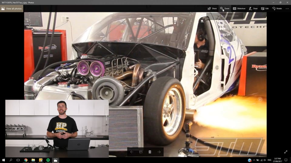
| 22:34 | If we can just jump across to my laptop screen again for a moment. |
| 22:38 | This is one of the 4G63 based cars we were involved with for some time and we are testing the two step launch control here on our dyno. |
| 22:47 | And as you can see we've got flames coming out the exhaust so the whole principal of how this works is it's used to build boost on the start line when we've got a really large turbo fitted to a small engine which naturally wouldn't be able to provide enough exhaust gas energy to spool that turbo up. |
| 23:06 | So how we get around this is we use a secondary rev limiter and while the engine is sitting on that rev limiter, we're using generally an ignition cut and we are retarding the ignition timing. |
| 23:18 | So what this means is that we are basically passing cylinders full of unburnt fuel and air out into the exhaust system and at the same time the ignition events that are still occurring are massively retarded so we're getting that combustion continuing out into the exhaust system where it ignites the unburnt fuel and air. |
| 23:36 | So we end up getting combustion occuring essentially in the exhaust manifold and in the exhaust housing of the turbo charger, provides a huge amount of energy to help spool that turbo charger up. |
| 23:48 | However from a negative aspect what it does create is large pressure spikes in the exhaust system and what this can result in is that exhaust valves actually being popped back open off their seats. |
| 24:01 | And with a hydraulic lifter this causes a huge issue because it allows that lifter to pump up to take up the clearance, that's what it's job is there to do after all, and then the valve is held open. |
| 24:14 | So essentially this means that there is no compression in the engine and you may have heard engines running hydraulic lifters using launch control or two step launch control, where they've gone up onto a launch control, popped and banged for a bit, come back to idle and they've either stalled or sounded like they're running on one or two cylinders, and that'll continue for a little while until the lifter bleeds back down and the valves actually close again. |
| 24:38 | So hydraulic lifters definitely not a good idea for our application. |
| 24:44 | OK so the plan, let's go over the components that we are using here for our Mitsubishi 4G63. |
| 24:52 | So obviously we're first of all talking about an extreme power level and an extreme RPM range. |
| 24:58 | And that requires that we do consider the components quite carefully. |
| 25:05 | In particular the weight of all of the components is really important. |
| 25:10 | We'll start with the pistons. |
| 25:12 | So first of all we're using JE forged pistons, that's just a company that we worked with quite closely and this allowed us to develop our own custom piston. |
| 25:23 | So this wasn't an off the shelf piston, and we went through several iterations as we developed our knowledge of the 4G63, found things that we needed to change, found areas of weakness where the pistons weren't surviving as well as we'd like. |
| 25:39 | So if we can just look at our other angle here, our other camera, this is unfortunately one of our earlier iterations of our 4G63 piston but it's still going to give you a pretty good idea of some of the features of this piston. |
| 25:56 | So first of all we can see that the piston is a flat top design so there isn't a dish which we would generally see in a factory 4G63 piston. |
| 26:06 | Now this, regarding, we need to consider the head gasket thickness as well as the combustion chamber volume. |
| 26:14 | And this generally got us to somewhere in the region of about 11:1 compression. |
| 26:19 | Now that sounds incredibly high for an engine that was designed to run on 54, 55 psi of boost pressure, however this is an aspect we can get away with due to the fact we were running on methanol fuel. |
| 26:34 | So this is a situation a lot of engine builders will find themselves in. |
| 26:40 | We need to creep up on a combination that works. |
| 26:42 | In a perfect world if we had an unlimited budget, what we would do is develop our engine and try a range of different compression ratios, we might try four different pistons with different compression ratios, no other changes, and see what the effect of those were. |
| 26:57 | In the end we ended up creeping up on our 11:1 compression ratio. |
| 27:02 | Certainly can't say that that was the ultimate for that engine but it certainly worked very well. |
| 27:06 | And by running that 11:1 compression ratio, it helps spool that turbo charger faster, it helps produce more power when we're off boost, which is in other words that's why we can spool that turbo charger a little bit better. |
| 27:20 | A huge consideration when we're running a really larger turbo on a small car. |
| 27:26 | The other aspect here it all things being equal, if we aren't knock limited we will end up producing more power with a higher compression ratio. |
| 27:34 | OK so another consideration here with our drag pistons were that we found over time that the factory 22 millimetre wrist pin that the 4G63 ran was flexing. |
| 27:47 | So again if we can just jump across to my other camera here. |
| 27:50 | What we would find is that when we pulled the engine apart there would be significant wear in the wrist pin bosses. |
| 27:58 | And while again we might think that all of the components we're dealing with here are very strong, in reality everything is flexing significantly when we're running at such high power and high RPM levels. |
| 28:10 | And we combatted this with two modifications, first of all we went from a 22 millimetre wrist pin, to a 23 millimetre wrist pin. |
| 28:19 | And at the same time we also increased the wall thickness of the wrist pin. |
| 28:23 | Now that is a little bit of a catch 22 because both of those modifications also result in an increase in the weight of the piston's wrist pin, so it's obviously something we don't want to do but we need to weigh up the positives and the negatives there and this gave us a wrist pin that definitely provided a much longer service life. |
| 28:47 | The other thing we did with these pistons is we reduced the compression height. |
| 28:51 | So again on our other camera, the compression height is simply the distance from the centre of the wrist pin boss to the crown of the piston. |
| 28:59 | So we reduced that compression height, we moved the wrist pin higher in the piston boss, and for those who are eagle eyed, this is not actually one of those pistons. |
| 29:08 | When we do this we actually find that the wrist pin will intersect with our oil control ring and this requires a oil control ring rail support. |
| 29:20 | So as I've said again this is one of our earlier iterations of our 4G63 piston. |
| 29:25 | Going to a reduced compression height was something that we did a little bit later. |
| 29:31 | And the design allows to run a longer connecting rod which I'll get into really shortly. |
| 29:37 | The other aspect in terms of improving the reliability of the piston came down to our pin boss design. |
| 29:44 | So again if we can just jump to this camera. |
| 29:47 | What we wanna do is create a lot of support for the wrist pin with very little bending. |
| 29:51 | So again this being an earlier design we can see there's quite a large gap between the two pin bosses. |
| 29:57 | And we really wanna minimise this so that the wrist pin is supported primarily in the pin bosses on either side of the piston and then in the small end of the connecting rod. |
| 30:09 | We don't want too much exposed wrist pin there that's going to increase the bending moment on the wrist pin and make it easier for that wrist pin to be bent or flexed. |
| 30:18 | So that's another consideration there that improved the reliability of our pistons. |
| 30:24 | We also, if we just jump across to the top of the piston, you can see that we were running these little holes that are around the outside edge of the piston crown. |
| 30:36 | These are called vertical gas ports. |
| 30:38 | And these really are only suitable for methanol fuel cars, because methanol burns very very cleanly. |
| 30:45 | If you're running on a gasoline based fuel you're going to fInd that these little gas ports will clog up very very quickly and basically render them useless. |
| 30:53 | So the idea behind these gas ports is they allow combustion pressure to get directly down in behind the top ring and force that top ring out against the cylinder wall so this improves the ring sealing which is really one of our key considerations in terms of making good power from our engine. |
| 31:16 | Really everything relies on a good seal from our rings. |
| 31:20 | OK so we've dealt with our piston design, now the next aspect we'll talk about is the connecting rods. |
| 31:26 | So we obviously again needed something that was incredibly strong here. |
| 31:31 | Originally because this engine was built with probably a fairly modest target of 600 or 700 horsepower in mind, we went for a Carrillo H Beam steel rod. |
| 31:42 | Carrillo are probably one of the brands or names that is well respected out there in the industry, and produce rods that may not be the lightest rod in the world but they are known for their strength. |
| 31:54 | So those rods actually proved to be very very effective. |
| 31:57 | They gave us a really long service life and we had very very little trouble with them. |
| 32:03 | They were just a reliable rod and that was all there was to it. |
| 32:07 | Moving on though once we started to increase our power levels and our RPM targets, we wanted to obviously reduce the reciprocating mass in the engine as far as we could. |
| 32:20 | So one of the areas that we could reduce this way was in the connecting rods and we went to a set of aluminium conrods. |
| 32:27 | Again if we can just have a look on our other camera here. |
| 32:30 | This is one of the connecting rods that we ran. |
| 32:33 | So despite the fact that clearly the alumnium connecting rod is a fairly chunky design, we've got a lot of thickness through the beam of the connecting rod due to the actual weight of aluminium it was quite a significant weight saving over the steel Carrillo rods that we had been running. |
| 32:55 | There are some really big considerations though if you are going to go to an aluminium rod. |
| 33:00 | First of all aluminium does tend to stretch and also grow with heat significantly more than a steel rod does so this requires that we take this into account with our piston to head clearance, our piston to valve clearance, we need to increase that clearance quite dramatically. |
| 33:18 | Normally somewhere in the region of about 60 thousandths of an inch over what we would deem suitable for a steel rod. |
| 33:24 | The other aspect with an aluminium rod is that they do have a fatigue life. |
| 33:29 | So these aren't a rod that you can just run indefinitely. |
| 33:33 | The actual life expectancy of the rod is an area of a huge amount of misinformation and unfortunately it's not possible to easily put a rock solid number on it which of course doesn't help. |
| 33:48 | The life expectancy's going to depend on the RPM that you're running to, the weight of the components in your engine, particularly the piston and the wrist pin that is attached to the end of the connecting rod, the RPM range, the power level, and of course then it comes down to how many runs down the drag strip you can get away with before you need to replace them. |
| 34:10 | So there isn't an absolute or a fixed number there. |
| 34:14 | We were sort of replacing these rods about once a season which in our case was probably in the region of about 70 runs down the strip. |
| 34:24 | Now when we went to the aluminium rod, or sorry one of the other advantages with the aluminium rod as well is that it is a lot more forgiving than a steel rod. |
| 34:35 | So a steel rod is very very strong and stiff, and what this means is that if we are running our engine on the absolute edge which quite often we will be when we're drag racing, if the engine experiences any momentary detonation, now this shock loading from the pressure waves inside the cylinder will be transferred very quickly down the connecting rod straight into the bearing and this can show up as damage to the big end bearings. |
| 35:03 | So with an aluminium rod this tends to absorb some of that shock loading. |
| 35:07 | So well obviously we can't expect any engine to provide a long service life if it is suffering from detonation, aluminium rods do give us a slightly wider window if we do momentarily run into detonation for some particular reason. |
| 35:23 | OK the other aspect that we went through with our aluminium rods was we actually chose a longer conrod than factory. |
| 35:32 | So the factory conrod length, and conrod length is simply the length from the center of the big end to the centre of the small end of the conrod, is 150 millimetres in the Mitsubishi 4G63. |
| 35:44 | Couple that with the fact that the stock crankshaft stroke is 88 millimetres, we did always stay with an 88 millimetre stroke in our engine just simply due to the RPM that we wanted to pull. |
| 35:56 | This gives a rod to stroke ratio for the factory engine of 1.7 Which on face value actually isn't bad. |
| 36:03 | However with a higher target RPM range in mind, anything we can do to improve or increase that rod to stroke ratio has to be a benefit. |
| 36:14 | We don't really care about low RPM torque with this sort of engine. |
| 36:18 | Everything was designed around that 8000 to 10500 RPM rev range. |
| 36:22 | So what we ended up doing was extending the length of the rod from 150 to 156 millimetres. |
| 36:29 | That goes in hand with the reduced compression height of the piston that we've already talked about. |
| 36:34 | And this increased our rod to stroke ratio from 1.7 through to 1.77 so a small but worthwhile improvement there. |
| 36:43 | OK in terms of the crankshaft, so this is another area that we do need to consider. |
| 36:50 | Let me just see, I've got a picture somewhere in here that's probably not quite relevant but there's a couple of things that I wanted to point out. |
| 36:58 | OK if we can jump across to my laptop screen. |
| 37:00 | OK so for those who are eagle eyed out there, you'll know that this is not a 4G63 block. |
| 37:06 | This is actually a 2JZ but I just wanted to show you some aspects of a factory crankshaft. |
| 37:13 | So we can see the counter weights on the crankshaft here. |
| 37:17 | When we started our 4G63 engine project, we performed one of the tasks that's quite well known in the factory component hot rodding market, which is the process of knife edging. |
| 37:30 | So that involves basically machining the leading edge of these counter weights or journals into as it's name implies, a knife edge. |
| 37:40 | And this just helps to reduce the windage loss as the crankshaft rotates through the oil mist in the crank case. |
| 37:50 | Now I'll just point out that I actually have drawn that knife edge on the wrong side, the crankshaft rotates clockwise so it's actually the other way around but you get the idea. |
| 37:59 | So with our very first iteration again just simply because we were starting with a relatively low power target in mind, we went with the factory crankshaft and what we ended up doing with our first crankshaft was modifying that stock crank. |
| 38:13 | We went through the process of knife edging it, we took a lot of weight out of the counter weights to reduce the reciprocating weight of the component. |
| 38:22 | And then we also went through the process of having the crankshaft nitrated which provides a thin surface treatment to the crankshaft which hardens it. |
| 38:34 | And we ran that crankshaft for a season and despite spending a huge amount of money on it and doing everything that we were told should be done to a factory crankshaft in that application, when we started really increasing the power and RPM range we found it cracked. |
| 38:49 | Now it never actually failed in service, we would find this out on a tear down and inspection, we'd have the crankshaft crack tested and we were quite frequently finding that the crankshaft would start to form cracks around the fillet radius of the main journal. |
| 39:05 | So as soon as you see that, obviously you don't wanna put that back into service. |
| 39:10 | So we went from there, obviously decided we'd found the limit of the factory crankshaft despite the modifications we'd made to it. |
| 39:17 | We chose one of the many billet aftermarket crankshafts that exist for the 4G63, there's a huge range of these now. |
| 39:25 | And we ran that for a season and we had no problems with that crankshaft, it worked quite well. |
| 39:30 | These come with basically knife edge counter weights so there's no work to do. |
| 39:36 | However we also found that the next time we tore that motor down and did an inspection and a freshen up on it, the billet crankshaft had also cracked. |
| 39:45 | Now that's a little hard to stomach when you're now spending perhaps 3500 to 4500 dollars on this expensive race component and it's still cracking, and really on face value providing no advantage over the stock crankshaft that we'd modified. |
| 40:02 | And the part that may surprise a lot of people out there is in the last few seasons of drag racing with that particular engine, our engine, we were running a 100% stock unmodified Mitsubishi 4G63 crankshaft. |
| 40:15 | And we were finding that unsurprisingly these were cracking but we would get a season out of the crankshaft with no failure. |
| 40:22 | We were running it to 10500 RPM, 1100 plus horsepower and it was putting up with that just fine. |
| 40:28 | And we were paying somewhere in the region of about $1100 for these crankshafts instead of 3500, 4000 so it was a slightly smaller bill to stomach at the end of the season. |
| 40:40 | OK so we've talked about the components that went into the engine and given you some background into those components. |
| 40:47 | I want to now talk about the modifications we went through with the engine block. |
| 40:52 | So first of all one of the biggest modifications we made was that we performed what's known as solid filling the engine block and this is a process where the water jacket in the block is filled with a block filling compound. |
| 41:07 | Often referred to as cement filling. |
| 41:09 | We actually used a specific compound that was designed for block filling. |
| 41:13 | It was made by Moroso, there's a range of manufacturers out there who manufacture similar products. |
| 41:18 | The idea behind the Moroso product is that it has the same thermal expansion coefficient or rate as cast iron so hence it shouldn't distort the block or the bores as the engine heats up. |
| 41:31 | Now of course if we do this, this removes any ability for us to run water cooling through the blocks. |
| 41:37 | So really limits our use here with the engine. |
| 41:40 | We can only do this because first of all we are using the engine for a drag application so it's only really being pushed up to the start line, started up, goes through a burnout and a drag pass, which may be sort of eight seconds or there abouts, and then we would be towing back down the return road, so it's only running for a very short time, and we're also running that methanol fuel which has really great cooling properties. |
| 42:03 | Often with methanol fuel it's actually quite hard to get the engine up to temperature in the first place. |
| 42:08 | So that provides additional strength to the engine block, it also provides additional support to the cylinders. |
| 42:15 | So for those who were finding problems with the bores cracking or splitting, solid filling the engine does have a huge advantage there. |
| 42:24 | Our next problem was the head gasket integrity, so by default the 4G63 uses an 11 by 1.25 millimetre head bolt. |
| 42:34 | Obviously one of the first moves would be to go to a head stud. |
| 42:37 | We actually went one step further and we replaced them with a larger diameter 12 by 1.25 millimetre head stud make out of ARP's L19 material. |
| 42:48 | So this provides additional clamping to the cylinder head and helps go one step further to improving the head gasket's seal. |
| 42:56 | That on its own isn't enough though, we also machined the engine block for an o-ring groove, so again if we could just jump across to my laptop screen, this isn't really showing specifically the o-ring grooves, but a further pass where you can see I'm installing that piston we can see on the subsequent cylinders there is a groove machined around the top of the bores. |
| 43:18 | And we went through several iterations of this. |
| 43:21 | In the end we were using a stainless steel o-ring wire that was fitted into the engine block that provided around about six to seven thousandths of an inch protrusion. |
| 43:32 | And that was used in conjunction with a multi layer steel head gasket. |
| 43:37 | And that provided us with a solution that was effective up to the 55 psi of boost we were running. |
| 43:44 | However it was still quite marginal and I think given the advances that we've seen recently, I would probably be stepping towards a different head sealing system. |
| 43:56 | What we're seeing with a lot of the high powered drag cars now is an aluminium alloy sealing ring that is used to seal around the top of the bores, it's actually a stepped ring that locates in a groove around the top of the ring. |
| 44:11 | And that's used in conjunction with a copper gasket to seal the oil and water jackets on the engine block. |
| 44:18 | So it's probably what I would use right now. |
| 44:20 | Just an interesting observation though that during the process we went through finding a solution that worked. |
| 44:28 | Obviously if we look at the engines that are making the most power we can look to top fuel dragsters, 8000 to 10000 horsepower from an eight cylinder engine. |
| 44:37 | And the head sealing system that is used in top fuel as well as top alcohol is a copper gasket which is annealed, this softens the copper gasket. |
| 44:47 | Then there is a stainless steel wire o-ring that can be located in either the cylinder head or the block and then there is a receiver groove machined into the opposite part. |
| 45:00 | So if we've got the stainless wire o-ring in the cylinder head there would be a receiver groove machined into the block. |
| 45:05 | So the idea there is that when the head is bolted in, the o-ring will distort the soft copper gasket and force it down into the receiver groove, essentially creating a lock that prevents cylinder leakage, combustion pressure leakage. |
| 45:21 | We actually tried that system with a 4G63 and it was a complete disaster. |
| 45:26 | We had the cylinder head gasket leaking worse than ever, we'd ever seen, at only a mild sort of 25 to 35 pound of boost. |
| 45:35 | So we put this down to the fact that our factory engine is simply too weak and moves around too much. |
| 45:44 | So we weren't able to make that system work. |
| 45:48 | The components in a proper top fuel drag engine are very very solid so they're not seeing that flexibility. |
| 45:55 | Now with the main cradle, I talked about the threading problems that we saw. |
| 46:01 | What we ended up doing there was again going to a stud kit instead of the factory bolts. |
| 46:07 | The run of the mill off the shelf ARP stud kit that everyone uses is great for a road going engine. |
| 46:14 | In our level we tried two modifications. |
| 46:17 | First of all we went from the factory 10 millimetre stud kit we stepped that up one size and we went to a 7/16ths stud, we found one that worked, machined the block to take that larger stud, threaded it, and we found that that ended up with the block cracking so that wasn't a great solution. |
| 46:36 | That I actually found at about the 1000 foot mark on a run down the drag strip at about 170 mile an hour, and my oil pressure light came on, warning me that the oil pressure was low, so I aborted the run and it didn't actually cause the engine to completely fail, but what it had done was cracked right through the bottom of the block. |
| 46:56 | We basically where we'd machined to take the larger studs, it'd taken too much strength out of the block, and allowed everything to crack under the loading that we saw down the drag strip, and we'd actually ended up with the block flexing because of the cracking so much, that the two balance shaft bearings, that block the balance shaft oil galleries fell out, and hence we lost oil pressure through there, so we're very lucky we didn't actually lose the whole engine. |
| 47:20 | The final iteration we ended up going to again a higher grade stud and that provided a pretty good solution. |
| 47:28 | OK the other thing I wanted to talk about here was the thrust bearing failure that I've mentioned and what we did to combat that. |
| 47:38 | So with the thrust bearing failure, I've talked about the crank warp problem. |
| 47:41 | Now again I don't have a 4G63 thrust bearing here unfortunately to show you. |
| 47:46 | So you're going to have to use your imagination. |
| 47:48 | But essentially the EVO 1 to 4 engines used a one piece centre main bearing, with the thrust washers and we ended up with one half in the block and one half in the cradle. |
| 48:02 | So let's have a quick look at this under our other camera. |
| 48:07 | So this is what the thrust surface of the bearing looks like. |
| 48:12 | So we're relying on oil flow off the bearing surface and down through these grooves that are machined, and the oil will then obviously make its way onto the thrust face of the bearing. |
| 48:23 | And that obviously wasn't happening. |
| 48:25 | So we tried a modification that worked really really well. |
| 48:28 | I'll just show you on this bearing what we did. |
| 48:30 | So you can see I've marked here with some black vivid, black marker, some little grooves. |
| 48:38 | And what we did was we had a machinist basically mill some grooves that follow these black lines into the thrust surface of the bearing. |
| 48:45 | And what this did was allow additional flow of oil down onto the thrust surface of the bearing where it could then migrate out across the bearing surface. |
| 48:54 | So it improved the oil flow to the thrust surface of the bearing and that improved the bearing life. |
| 49:01 | The other aspect that's really important with the 4G63 we found was the oil holes in the bearing shell that align with the galleries in the block, on the centre main bearing there is a very very large misalignment here. |
| 49:16 | So we might have the oil hole somewhere like this in the bearing shell. |
| 49:21 | But the oil gallery in the back of the bearing shell in the block comes through quite a distance away. |
| 49:27 | So what we ended up doing was machining a slot so that that aligned correctly, again increasing the oil flow through to the thrust face of the bearing. |
| 49:36 | And we found that that alleviated all of our thrust bearing failure problems and is something we did on all of our engines regardless of whether is was for a drag application or a street application. |
| 49:51 | On top of that to combat the lubrication problems we've talked about with the oil starvation on a launch as well as hitting the chute at the end of the strip, we went to a four stage Peterson dry sump system which required us to also fabricate a dry sump itself to replace the factory wet sump so this was a low profile sump with three scavenged stages which went to the dry sump pump. |
| 50:19 | OK we've got one more section to cover and then we'll move into some questions. |
| 50:23 | So if you do have any questions, please ask those in the comments or in the chat, and I'll get to those really shortly. |
| 50:31 | OK so in terms, the last thing we'll really talk about here is the cylinder head and it sort of probably should go without saying that it was fairly extensively ported and polished to improve the air flow. |
| 50:42 | In conjunction with this we were using a set of one millimetre oversize stainless steel for air valves. |
| 50:48 | Now one of the aspects when you go to a set of aftermarket stainless valves which is really common, is that the stainless valve stem is not particularly compatible with a factory cast iron valve guide. |
| 51:02 | I know a lot of people do get away with it but it certainly isn't recommended, it can cause galling between the valve guide and the valve. |
| 51:11 | So that combined with the other known problems that cast iron valve guides give, we went to a set of bronze valve guides. |
| 51:20 | So that's a really common modification for anyone who is building a cylinder head to run with stainless steel valves. |
| 51:29 | In order to control the valves with the larger cams that we're running as well as the higher rev range, we went to a set of double valve springs using titanium retainers. |
| 51:41 | Again pretty common upgrade here. |
| 51:43 | Now for a street application we're using a mild cam, this actually gets really easy where there's a bunch of selections of off the shelf parts. |
| 51:50 | However when you're starting to develop an engine that's going to run to 10500 or 11000 RPM, particularly when you're using a very very large and aggressive cam profile with a lot of lift, we start to get a lot trickier, we struggle sometimes to find a valve spring that can provide enough seat pressure while still providing enough valve lift before we reach coil bind. |
| 52:16 | So that was a tricky aspect of the design and it's quite important in these sorts of applications to make sure that your spring pressure is absolutely perfect so you're not going to end up with valve float. |
| 52:30 | In terms of the cams we're running there, we worked quite closely with Calfred cams, these were a custom grind but essentially they were providing around about 300 degrees of advertised duration along with about 12 millimetres of valve lift. |
| 52:45 | So these cams really need to be designed to improve the air flow up in that 8000 to 10500 RPM vicinity, that's really what we were interested in. |
| 52:56 | And in order to do that of course we're going to be giving away a lot of our low RPM efficiency, again with the large turbo on a small engine, that's not a consideration that we're going to really worry too much about. |
| 53:10 | With a set of cams that large as well you need to understand that your idle quality is going to be significantly affected there. |
| 53:18 | So in this case we had our engine idling at around about 1600 or 1700 RPM. |
| 53:25 | So in our final guise if we can jump across to the laptop screen, this is probably one of the last dyno sheets that I actually managed to save. |
| 53:35 | Unfortunately it isn't the final one. |
| 53:37 | So on this particular run we were just on 800 kilowatts at the wheels on a Dynopack chassis dyno. |
| 53:45 | And as you can see here the blue line is our boost pressure. |
| 53:51 | Boost pressure's on the left axis. |
| 53:53 | That particular run we're just over 50 psi, around about 51, 52 psi. |
| 53:59 | And you can see I actually aborted that run at about 9800 RPM. |
| 54:03 | So in its final guise we ended up with 1166 wheel horsepower running to 10500 RPM. |
| 54:12 | Well actually made peak power at around about 9500 RPM. |
| 54:16 | Also, where are we, the other aspect I mentioned as well with the lifters, just on my laptop screen there, we did go to a custom solid lifter. |
| 54:28 | So what we did there was we simply took the factory hydraulic lifter, disassembled it, removed the internal check valve and spring mechanism and made up a piece of bar that went in there and we machined the bar to achieve our clearance. |
| 54:43 | So the problem when you go to a solid lifter design is that it is quite labor intensive so the process I'm going through here is using feeler blades to check and set the valve lash. |
| 54:54 | This does need to be checked reasonably regularly. |
| 54:57 | And an important aspect here as well is that if you are going to run a solid lifter, or convert a hydraulic lifter engine through to a solid lifter engine, it does require a different cam profile. |
| 55:11 | There's quite subtle differences, subtle but important differences in the cam profiles between a hydraulic cam and a solid cam, and they aren't backwards compatible. |
| 55:22 | So something that you do need to keep in mind. |
| 55:25 | Alright so in terms of that engine as well, we actually found it to be reasonably reliable, all things considered. |
| 55:32 | We actually only had one failure, catastrophic failure at the drag strip and it really wasn't the engine's problem. |
| 55:39 | The last time I ran that engine, we had been having trouble with the boost controller that we were running. |
| 55:47 | I did a run down the strip and I should've been running about 35 to 40 psi of boost, I ended up coming back and it'd been on wastegate spring pressure of around about 22 psi. |
| 55:57 | So I got rid of the boost controller that we had been trialling and we went back to using the ECU to control boost. |
| 56:04 | I set up the boost control in the ECU to give me what should've been a relatively low boost level just so I could do a check out run, make sure everything was OK. |
| 56:15 | The reality was somewhat different. |
| 56:16 | What I had forgotten is that in the time I'd been using the external boost controller, Motec had gone through quite a large revision of their ECU and there was one parameter in the boost control strategy which needed to be changed, and essentially it's a strategy where either a number of 0% in the duty cycle table could be requesting minimum boost or it could be requesting maximum boost. |
| 56:41 | So forgetting this, which was 100% my fault, I went out on the drag strip asking for what I though was minimal boost, came off the line, the car felt really really strong, pulled second gear and the warning lights on the dash came up for I think it was exhaust gas temperature and before I had a second to react to that, there was water all up the windscreen. |
| 57:03 | And when I looked at the data logging what I found is that we'd left a line with about 40 psi of boost and then I hooked second gear, it had shot up to 65 psi which actually was the limit of the map sensor's reading so I don't really know what I got. |
| 57:16 | What it did was it lifted the head, torched a huge channel through the top of the cylinder block as well as the head and basically sprayed water everywhere. |
| 57:24 | So that aside, other than regular maintenance, we actually had really good life expectancy out of the engine. |
| 57:31 | Components such as the pistons and the connecting rods were replaced and the crankshaft were replaced once a season and generally it would be pulled down after about five meetings just to check the bearings and make sure that those were all looking good. |
| 57:44 | In between that after every meeting we would peform an oil change and we would inspect the oil filter and make sure we weren't seeing any bearing material, foreign material in the oil filter. |
| 57:55 | Alright let's have a look at some questions and see what we've got. |
| 58:06 | OK our first question comes from Alex who's asked what kind of bearing clearances are you using on an engine that spins over 10000 RPM? OK so in this particular engine we were running bearing clearances on the main bearings around about 2.5 thou. |
| 58:20 | I am going to talk here in imperial measurements. |
| 58:23 | Obviously for those of you who want metric, it's pretty easy to convert. |
| 58:26 | And we were running around about 2000ths of an inch on the big end bearings. |
| 58:31 | So this is just a little bit looser than the factory specification, a little bit loser than what I would normally run a factory engine. |
| 58:38 | And the reason for this was to ensure that we did get good bearing life at high RPM. |
| 58:42 | Again just like I've talked about with a few of the components, we could consider that the crankshaft is nice and solid, nice and rigid when we've got it sitting on our workbench. |
| 58:51 | Likewise the engine block. |
| 58:53 | The reality is that at 10000 RPM and above, particularly with sort of 1100 plus horsepower, everything's moving around and that crankshaft probably resembles a piece of spaghetti. |
| 59:05 | So what we want to do is allow enough movement, enough clearance in those bearings to ensure that when that crankshaft is inevitably flexing and the block is inevitably flexing, we don't get metal to metal contact between the journal and the bearing shell. |
| 59:19 | And we used a slightly larger clearance along with a very very high quality Motul 300V 50 weight synthetic oil to provide a thicker as well as a stronger oil lubricant film on the bearings. |
| 59:39 | TDE Champs asked, any experience, opinions, or hearsay with cryo treating engine parts? Look I honestly think it's one of those fringe treatments. |
| 59:49 | And I certainly can't say that it is no use. |
| 59:54 | I'll give you my experience with cryo treatment, not on the engine components because it isn't something that I did with the engines. |
| 01:00:01 | However in my earlier days where we were still running a factory gearbox and having reliability problems with the gear set as you could expect, we did try cryo treating the gearbox and I really noticed absolutely no improvement in strength from that process. |
| 01:00:17 | Now I will say there's probably a caveat here is cryo treating might be really beneficial if you're looking at maybe a 20, 25% increase in power over stock. |
| 01:00:29 | We were taking a stock gearbox, again designed for 300 horsepower, and I think at that time we were trying to jam about 800 horsepower through it. |
| 01:00:37 | I don't really blame the gearbox for failing and I don't really expect that the cryo treatment was going to work miracles. |
| 01:00:44 | So take that for what you want, I haven't honestly done enough testing in a controlled manner to really say with certainty that it's useful or not. |
| 01:00:56 | Wittlebeast has asked, I think that you wanna round nose on the leading edge of the crank and knife edge the trailing edge, all fast fish are shaped like that way, god figured it out a long time ago. |
| 01:01:07 | Yeah probably pretty good point and probably my explanation of that process wasn't quite accurate. |
| 01:01:13 | We were basically putting an aerodynamic shape, a wing shape if you like, on the crankshaft counterweight, so it wasn't a case of just applying it to one edge of the counterweight. |
| 01:01:26 | I again haven't done it back to back and whether a knife edge, and actual sharp knife edge versus a rounded leading edge on the crank is beneficial or not. |
| 01:01:35 | As you say, probably aerodynamics suggests that it is an advantage. |
| 01:01:42 | Tyler's asked when upsizing the head studs, what process was used to install new threads in an aluminium block? It's a really horrible process to be perfectly honest. |
| 01:01:52 | It's a process that I would recommend leaving to your engine machinist. |
| 01:01:56 | However I have at a pinch done it in our own workshop. |
| 01:02:00 | One of the key aspects here is that you need to make sure that when you're drilling the existing holes in the block, oversize, you need to make sure that you're drilling perfectly concentric with the existing holes, and that's really quite tricky to do. |
| 01:02:17 | Certainly you can't do this with a handheld tool like a drill. |
| 01:02:21 | So if you've got a really solid, really really good quality drill press then you are able to do this. |
| 01:02:27 | Generally you could get your machinist though to do it on a mill which is gonna ensure the reliability and the concentricity of the holes. |
| 01:02:38 | So the process is really to find out what your final stud thread is going to be. |
| 01:02:47 | So for example if you're going to 11 by 1.5 or let's say 12 by 1.5, what you generally do is the drilling size for tapping is we take the 12, the final size, 12 millimetres, and we remove the pitch off that. |
| 01:03:05 | So 12 by 1.5 we take 1.5 millimetres off it, so our actual drilling size would be 10.5 millimetres. |
| 01:03:13 | Then we simply want to run a tap through it. |
| 01:03:15 | Also wanna take our time with this and make sure that the tap is well lubricated, we want nice sharp crisp threads in the block, we don't want to end up with oversized threads because that risks having those threads pull out. |
| 01:03:31 | Michael's asked, I'm also using the Moroso block filler on, I'm not sure what that is, a top quarter way bottom end is B18A1 H Beam rods, JE pistons on E85, wanted to know if it will still help. |
| 01:03:48 | Can't quite read the question there so that's not really helping me. |
| 01:03:52 | The block filler, you do need to be a little bit careful with it. |
| 01:03:56 | So first of all that Moroso product is designed for cast iron blocks. |
| 01:04:03 | So if you actually look at the Moroso product, it actually states that it has the same thermal expansion coefficient as cast iron. |
| 01:04:10 | Now clearly that's gonna be a little bit different to aluminium. |
| 01:04:13 | So I'm not 100% sure if that would be a good compatibility with an alloy block. |
| 01:04:18 | Certainly I'd be a little bit concerned about it, and you'd wanna make sure that it is suitable. |
| 01:04:23 | I know that a lot of engine builders that I deal with have used a special epoxy for solid filling alloy blocks. |
| 01:04:31 | Now in terms of E85, it does have better cooling properties than gasoline but certainly you do need to be a little bit careful, it does run a lot hotter than methanol. |
| 01:04:42 | One of the tricks that is common is to only partially fill the water jacket with the block filling compound. |
| 01:04:50 | Now that can provide some advantage, certainly it is going to improve the strength of the block. |
| 01:04:55 | However the main pressure, the main combustion pressure that is occurring generally is in the top sort of third of the engine block. |
| 01:05:01 | So if you're only filling the bottom third, or maybe up to halfway up the engine block, you're probably not going to get the full advantage out of that block filling compound. |
| 01:05:11 | Next question comes from John who's asked, Cometic MLS versus cut ring head gasket, which is better for daily driving making a max of 28 pounds. |
| 01:05:19 | OK so first of all I'm gonna just have to come out and say that I have had absolutely zero success on any of the moderate to high power projects that we've built using a cometic gasket. |
| 01:05:32 | I simply have not been able to make these gaskets seal. |
| 01:05:35 | I don't know if it's something to do with our machining techniques or it is the gasket itself, I have no doubt that there are people around the world getting good success with the cometic gasket. |
| 01:05:47 | Just to come back to our 4G63 application, we got the best results there using an HKS stopper type multi layer steel gasket. |
| 01:05:57 | I found those were far far superior to the cometic gasket. |
| 01:06:01 | So at 28 psi of boost, 28 psi on its own is not a lot of information. |
| 01:06:08 | 28 psi with a TD05 turbo versus 28 psi with a Garrett GT4202 is gonna be worlds apart. |
| 01:06:17 | So if you're talking about a mild street engine that's making reasonably good power, probably wouldn't need to worry about o-ringing. |
| 01:06:26 | But as I say I mean my own experience, I probably wouldn't be choosing the cometic gasket either. |
| 01:06:32 | Dave's asked can you touch a little more on the newer cylinder head sealing o-rings that's being used nowadays that I mentioned? Yeah so this was something that we used on a couple of the last 4G63 drag engines that I built. |
| 01:06:45 | And this is something that I have done a lot of testing on. |
| 01:06:48 | There's so many theories about what works and what doesn't. |
| 01:06:51 | As I mentioned with the top fuel example, a technology that's proven at the upper echelon of drag racing, the most powerful engines in the world, simply was an utter failure on our little silly import engines just because of the flexibility of the components. |
| 01:07:06 | So then I've also tried gas filled o-rings, where we machined a groove into the top of the cylinder bore and the o-ring sits in the top of the cylinder bore. |
| 01:07:16 | And basically the theory is that the gas filled o-ring will expand under combustion pressure, under combustion temperature and help seal. |
| 01:07:27 | So what we're trying to do is come up with a product that will expand to allow the cylinder head to flex off the block just marginally without losing that seal. |
| 01:07:39 | So the product that we used, the one that I mentioned, was an aluminium bronze sealing ring. |
| 01:07:44 | So it's a solid ring, it's not gas filled, it's a solid ring of an aluminium bronze alloy. |
| 01:07:50 | And it's stepped so again we basically machine an o ring groove into the top of the bore and the step on the aluminium bronze sealing ring slots down into that step, and then the aluminium bronze ring locates against the cylinder head. |
| 01:08:04 | So on its own there's nothing particularly special about it, and I know that the first time I used one of these I was quite sceptical about whether or not it would work. |
| 01:08:12 | So we had four of these rings, obviously on an inline four cylinder engine. |
| 01:08:16 | Those are doing the actual cylinder combustion pressure sealing but we still have to worry about the oil and water jackets, oil and water galleries in the block. |
| 01:08:27 | So these are sealed with a copper head gasket. |
| 01:08:30 | Which in itself is a little bit problematic. |
| 01:08:33 | Copper gaskets don't seal particularly well so getting those to seal really really thoroughly is a bit of a challenge. |
| 01:08:40 | So those rings will expand with temperature and they provide a really good seal. |
| 01:08:46 | I can't give you too much detail, simply because I'm not aware of it, on the physics behind how they work, but I can tell you that the work very very well. |
| 01:08:57 | Anthony has asked can you explain when to use gapless top rings with pistons without gas ports? So I've actually used gapless rings on some of our 4G63 drag engines. |
| 01:09:09 | I've had reasonably good success with them. |
| 01:09:12 | However if we've got our ring gaps dialled in properly, I don't actually know if they offer that much of an advantage. |
| 01:09:21 | I certainly never saw any real performance advantage in terms of power. |
| 01:09:25 | What you will notice if you're running a gapless ring set is if you do a leak down test on the engine, the cylinder leakage is exceptionally low. |
| 01:09:34 | But yeah as I say I never really bore out as a real advantage in terms of power on the dyno. |
| 01:09:43 | Wittle beast's asked on our car was traction control required for the entire 1320, if so were you ever at full power? OK so on our car, being a permanent four wheel drive car, with essentially we ran three lock differentials. |
| 01:10:02 | At that point in time we didn't really have access to the technology to run a proper traction control system. |
| 01:10:09 | What we were using is a function that was in the Motec 100 series ECUs which was an RPM rise rate funciton, which is combined with the two step launch control, or dual RPM limiter as it was called. |
| 01:10:24 | Which limited the rate that the RPM could increase from the two step rev limiter when the clutch was dropped. |
| 01:10:29 | So this helped control wheel spin through first gear as we came off the line. |
| 01:10:35 | Beyond that the traction control was all done through the right foot and extensive logging, looking at where we were getting wheel spin, and we were using both gear dependent and speed dependent boost control. |
| 01:10:48 | So we'd leave the line with somewhere around about 20 psi of boost. |
| 01:10:51 | As the car went down the strip and we went through the gears we would step the boost up. |
| 01:10:55 | So it was only really the last probably couple of hundred, few hundred feet of the drag strip where we were actually seeIng maximum boost in top gear. |
| 01:11:07 | Godspeed's asked thoughts on head gasket types for alloy head and block? Again really one of my go to's for the moderate to reasonably high powered engines are something like the multi layer steel gasket. |
| 01:11:24 | Those are a really good option but everything we've just talked about in terms of those sealing rings or o-rings is still going to work exceptionally well on an alloy block. |
| 01:11:35 | Our next question comes from Andrew who's asked in your opinion given the advances in modern technology since you last campaigned the car, what modern technology would you think would yield largest improvement in the performance of the engine? Look I'll be perfectly honest, when we were campaigning that car, we were in a situation where I was obviously an engine builder and I was an engine tuner and for me the drag strip was a really good way to test what we were doing back at the workshop. |
| 01:12:04 | And my whole strive while we were campaigning that car was for maximum power. |
| 01:12:10 | Everything we did was all about power. |
| 01:12:12 | And it actually probably hurt the car in terms of its outright ETs. |
| 01:12:17 | That particular car never ever 60 footed really well which is for drag racing, the 60 foot time is really the indicator of how well the car is getting off the line. |
| 01:12:29 | And really that is the key to putting in a really fast ET. |
| 01:12:32 | We want to get the car up and moving as quickly as we can. |
| 01:12:36 | Now four wheel drives never really 60 foot that well, but in our case we ran a best ever of about a 1.35 60 foot. |
| 01:12:44 | On its world record ET it actually ran a 1.45 60 foot, which is really really average. |
| 01:12:53 | So just, I mean this is a round about answer to your question but I think it's just important to get this through. |
| 01:12:58 | One of the later cars we worked on for a customer was an Evo 9 and we went about this completely the opposite way. |
| 01:13:03 | We forgot about power, we knew how much we needed to make in order to get our final result, but everything we focused on was getting the power to the ground, making the chassis work. |
| 01:13:13 | And this gave us much better results. |
| 01:13:16 | We ended up running very very similar ETs with less power and the car was much easier to drive and it didn't break as many things. |
| 01:13:24 | So in terms of your actual question, what technology would yield the largest improvement in performance I think probably if we needed more power the advances in turbo technology are probably where that would come from. |
| 01:13:38 | There's been massive steps forward since the relatively average T51 that we were running at the time. |
| 01:13:45 | And the newer turbos that we've seen from Garrett and Precision are miles ahead. |
| 01:13:51 | We weren't even running at that time, a billet compressor wheel for example. |
| 01:13:58 | Sorry I saw a bunch more questions in here. |
| 01:14:02 | So yeah that's talked about the turbo chargers. |
| 01:14:06 | ECUs, so I think this is a really common misconception, that we need the best, latest, greatest ECU in order to go drag racing and the reality is that drag racing, while we are obviously making huge amounts of power, is a relatively easy area to tune for. |
| 01:14:23 | We're only running across a really narrow power band, RPM range, and we're also running continuously at full throttle so the actual fuel and ignition control of the ECU is actually relatively straightforward. |
| 01:14:37 | What we are seeing though and this is always my drive, is to incorporate everything inside the one box. |
| 01:14:43 | And this means that we can use the ECU for boost control, we can use the ECU sometimes for our gear shifting as well. |
| 01:14:51 | And this means we've got a lot more control over everything that's going on. |
| 01:14:56 | Traction control which we've kind of touched on, obviously there have been some advances in our ability to run that as well so that would've been useful and I know there's aspects now where the driveshaft speed is monitored, this is on a two wheel drive drag car, and it is mapped against an ideal, and it's basically a passive type of traction control for drag racing classes where actual traction control is not legal. |
| 01:15:22 | Alright I'll move on now. |
| 01:15:23 | next question comes from Jay who's asked, what spark plug and gap did you use to make that power and was it a resistor plug. |
| 01:15:29 | Yeah so in EFI I generally always run a resistor plug. |
| 01:15:33 | You find that with non resistor plugs you can quite often end up with problems with interference. |
| 01:15:38 | We were running an NGK BR10EG, or BR11EG, I can't quite remember, we went through a few series of them. |
| 01:15:46 | And generally I'd be running a spark plug gap somewhere in the region of about 18 to 22 thousandths of an inch so quite tight. |
| 01:15:54 | And this was also coupled with a very high power CDI. |
| 01:15:59 | Justin has asked any experience with coatings versus WPC treatments? WPC, I am aware of what it is, not something we have access to easily here in New Zealand so I've had no experience. |
| 01:16:10 | So I've watched with interest, the guys over at Motor IQ use that treatment a lot, and I mean certainly it makes a lot of sense, I just can't give you first hand experience. |
| 01:16:19 | Only coatings that I personally use, while the piston I've been showing you all, doesn't have any coatings on it, I do use the anti friction coatings on the skirts of pistons. |
| 01:16:30 | I have tried the ceramic heat barrier coatings on the crowns and again never really been able to do it back to back but haven't seen any significant improvement from it. |
| 01:16:42 | Barry has asked would you consider getting into the drag racing game again and if so what platform would you go with? Yeah absolutely I mean it is always a passion, and I think that's probably where I got into the motorsport industry in the first place. |
| 01:16:57 | For me again as an engine builder and a tuner it is the perfect place to test your results. |
| 01:17:02 | I mean you can throw around dyno figures on the internet and they really are meaningless. |
| 01:17:08 | You can get a dyno to read just about anything you like if you're maybe a little bit devious, but when you get to the drag strip, the mile an hour and the ET don't lie, so you can't fake a drag result. |
| 01:17:22 | So that's one aspect that I like about drag racing. |
| 01:17:25 | In terms of a platform I think I found with the Mitsubishi projects that we were involved in, while they are very rewarding when they go right, one of the difficulties really for me was the drive train. |
| 01:17:38 | I was simply trying to get so much power through a drive train, even with the best internal components, we were running a PBG four speed drag dog set in our gearbox, we're still restricted to the factory gearbox casing, and the axles, everything was just a reliability problem. |
| 01:17:56 | So if I got into it again I would probably be looking at something like a proper pro mod twin turbo V8 chassis, and something where all of the components you can put into that car are reliable and able to put up with the sort of abuse that they're getting. |
| 01:18:16 | Wittlebeast asked have you ever tried to allow for crank twist at those power levels regarding timing per piston location from the flywheel? I've heard about some insane crankshaft twist. |
| 01:18:27 | Not on our inline four and I mean think in all honesty, short of having actual in cylinder pressure transducers that you could see exactly what's going on, I think you'd only be guessing, so no not something I've really delved into. |
| 01:18:41 | but definitely crank twist would be a very very real aspect there, and again just comes down to what I've been mentioning here. |
| 01:18:50 | All of these components which seem so stiff and rigid when they're sitting on the workbench, at those sort of power and RPM levels, are twisting around like a piece of spaghetti. |
| 01:18:58 | Zach has asked would you say when setting main or rod bearing clearances following a one thou of clearance per inch of journal is a good rule of thumb with adjustments made depending on application and Intended use? Yeah absolutely that's always been the rule of thumb for bearing clearances and it certainly does hold true in most instances. |
| 01:19:19 | You will find if you're dealing with an aluminium block, then the clearances are a little different with alloy because the block tends to expand a little bit more with heat. |
| 01:19:30 | One of the guides I normally use, particularly if you've got no prior experience, prior knowledge, is to look at what the factory clearances are, the factory recommended clearances. |
| 01:19:40 | Now these are obviously going to be ideal for a completely stock engine, they'll work for mild to moderate increases in performance. |
| 01:19:47 | And I generally tend to base my decisions on final clearances around those factory clearances, and again if I'm involved in a development project like our 4G63 drag engine program, you get the opportunity to test. |
| 01:20:01 | We probably built maybe a couple of dozen, maybe more of these high powered drag engines over the years for ourselves as well as customers. |
| 01:20:10 | So you're constantly seeing these come back. |
| 01:20:12 | You get to strip them down and see what the bearing condition looks like and you can make small adjustments to your final clearances based on experience there. |
| 01:20:22 | Darius has asked how often would you perform an engine freshen up and what did that include on our drag Evo? So covered this briefly but basically once a season so probably in the region of about 60 to 80 passes we would end up with a brand new set of pistons, brand new connecting rods, and a brand new crankshaft. |
| 01:20:42 | We got in the region of about two seasons use out of an engine block before that was trashed. |
| 01:20:48 | The cylinder head also was freshened after each season which involved having the valve seats recut. |
| 01:20:55 | We would also be checking in between, probably about every three to five meetings we ran, depending on at what power level, where exactly we're at, we would be checking the bearings, making sure those are OK. |
| 01:21:08 | Sometimes those would need to be replaced during the season and we'd also be checking the oil filter, cutting that open and looking for any bearing material in there after every single meeting, just to get on top of any problems before they became serious. |
| 01:21:24 | Also probably every meeting we would be checking and maybe making adjustments to the valve clearances as well with those solid lifters. |
| 01:21:35 | Alright guys thanks for all of your questions there, some really great ones and hopefully that's given you some more insight into a topic that probably a lot of engine builders are interested in, but maybe some will probably never work in that range. |
| 01:21:48 | So everything we learn there of course does filter down and is still 100% applicable to our design processes for slightly more mild and moderate engine combinations. |
| 01:21:59 | As usual if you do have any more questions, please ask those in the forum, and I'll be happy to answer them there. |


