204 | HP Tuners MAF Re-Scaling Made Easy
Summary
In the majority of factory cars a MAF sensor is used to tell the ECU what mass of air is entering the engine. In stock form the calibration of this sensor is likely to be close to perfect, however as soon as we make any changes to the intake system the MAF calibration can become inaccurate. In this webinar we’ll see how we can use a Wideband meter and the HP Tuners VCM Scanner software to optimise the MAF calibration in our 2006 GM LS2 engine.
| 00:00 | - Hey guys, Andre from High Performance Academy here and this time we're going to be looking at some techniques for calibrating a mass air flow sensor, particularly important if you are retuning or reflashing any late model factory engine. |
| 00:15 | And while there are still a few ECU manufacturers or OE manufacturers I should say, that prefer the speed density system, Ford is one that pops to mind, by far and away the majority of OE manufacturers are using a mass air flow sensor. |
| 00:31 | So it's a technique that is really really powerful and it's a technique that is worth understanding. |
| 00:36 | And I think particularly a lot of tuners that come from an aftermarket ECU tuning background where almost always the speed density system is employed, the MAF sensor doesn't get a look in, it's chucked in the bin, these tuners aren't familiar with a mass air flow sensor and it can actually be a little bit daunting considering going and tuning a mass air flow sensor based ECU. |
| 00:58 | It's, as you're going to hopefully see today, that's actually not a problem at all and retuning using a mass air flow sensor is incredibly easy. |
| 01:09 | And if you actually understand what you're trying to do, once you've got that mass air flow sensor calibrated correctly, you're going to find that your actual tuning process becomes very very simple, very very straightforward. |
| 01:21 | So definitely worth understanding and putting in your little bag of tricks. |
| 01:26 | Now it's also worth mentioning here that when it comes to rescaling the mass air flow sensor, there isn't one single way that you have to do it. |
| 01:35 | There's a variety of techniques and then there's a variety of takes on those individual techniques. |
| 01:41 | So what I'm going to show you is the technique that I personally use, I've found it to be incredibly effective but just understand that there are a few other ways of going about this. |
| 01:51 | Before we get into that we need to obviously start by understanding what the mass air flow sensor is. |
| 01:57 | I'm hoping that unless you've been lying under a rock for the last few years, you probably do understand but let's just jump in and have a quick look. |
| 02:04 | So we'll head across to my laptop screen, this is the engine bay on our SS Commodore. |
| 02:09 | For those who don't get these in their local market, this is powered by the L98 GM engine, essentially for all intents and purposes, an LS2 six litre V8. |
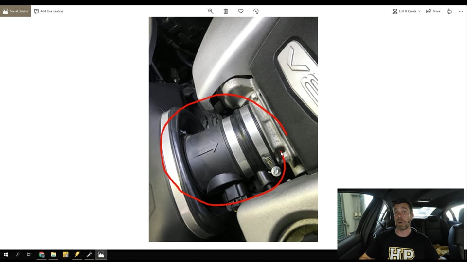
| 02:19 | So we've got our mass air flow sensor fitted here on this engine, not quite in the stock location because we are running a VCM suite OTR or over the radiator cold air intake. |
| 02:30 | So that relocates that mass air flow sensor straight onto the inlet of the throttle body. |
| 02:34 | In a normal engine bay it's gonna be mounted somewhere over here, there's a little bit of tubing that runs to that and it mounts off the factory air box. |
| 02:43 | Got a slightly closer look at that particulal mass air flow sensor. |
| 02:47 | But in essence the important point to note here is that the mass air flow sensor is located in the air flow so that all of the air flow going into the engine passes through it. |
| 02:58 | And what it does here is it basically converts that air flow into a output that it can send to the ECU. |
| 03:05 | In this case with this generation of LS engine, this is a frequency based air flow meter. |
| 03:12 | So it outputs a frequency in proportion to the amount of air passing through it. |
| 03:16 | We'll just have a quick look and see what that all looks like inside our VCM editor software. |
| 03:21 | So we are on our air flow tab and under air flow we are on general. |
| 03:27 | And the part that we're interested in right now is our mass air flow sensor calibration. |
| 03:32 | So let's have a quick look at that. |
| 03:34 | So this is a two dimensional table of our mass air flow sensor frequency in hertz versus our air flow. |
| 03:41 | And in this case we are looking in metric units, grams per second. |
| 03:45 | So in essence what this means is that if the mass air flow sensor was outputting a value of 3300 hertz, this would tell the ECU that we have an air flow of 9.75 grams per second of air entering the engine. |
| 04:00 | Now we'll just have a quick look at this graphically before we go on because it doesn't make a lot of sense when we are viewing it just numerically like this but when we look at it as a 2D graph we've got our air flow on a vertical axis in grams per second and we've got our mass air flow sensor frequency in hertz on the horizontal axis. |
| 04:18 | The important point to note, and particularly if you are looking at a calibration that someone else has done it's just looking at the general shape of this curve. |
| 04:29 | And in a well calibrated mass air flow sensor, we should be seeing this nice smooth exponential shape to our mass air flow sensor curve. |
| 04:38 | If we've got big peaks and troughs in this or it's bumpy, lumpy or otherwise horrible, this indicates there's problems here, you're almost certainly gonna have some drivability problems and the mass air flow sensor calibration is probably one of the first places you're going to have to look. |
| 04:57 | Alright so now we've got a basic idea of what that mass air flow sensor is, I just wanna get down to why it's so important and why a lot of people misunderstand or overlook its importance. |
| 05:06 | Basically we need to understand that the factory engine control module or ECM is scheduling all of its fuel as well as its ignition outputs based on the output from our mass air flow sensor or the input I should say, from the mass air flow sensor. |
| 05:22 | So for our ECM to correctly calculate what pulse width to supply to the injectors in order to achieve a specific air fuel ratio, we first of all need to know what mass of air is entering the engine. |
| 05:34 | This is because when we're looking at an air fuel ratio, let's say for example our stoichiometric air fuel ratio of 14.7:1, that is simply a mass ratio. |
| 05:43 | We're talking about 14.7 parts of air to one part of fuel, let's say we're talking in grams, 14.7 grams of air flow into the engine versus one gram of fuel being supplied from our injectors. |
| 05:56 | So if the ECM knows accurately what mass of air is entering the engine, provided of course that our injector characterisation tables are also valid and correctly entered, then it's incredibly easy for the ECM to calculate the correct pulse width to achieve our target air fuel ratio and everything just falls into place, we're not chasing problems, under closed loop control the ECM's going to be able to accurately achieve our stoichiometric air fuel ratio when we're in power enrichment, when we're asking for more power from the engine and we're at wide open throttle then the ECM is going to be able to accurately track our power enrichment target air fuel ratio or EQ equivalence ratio target table. |
| 06:39 | So if we get this right, everything else becomes easier, we're going to be talking mainly about fuel today, but of course this also corresponds to our ignition tables because the load axis for our spark tables is based on mass air flow in grams of air per cylinder. |
| 06:56 | So this is the basis for all of our tuning. |
| 06:58 | Alright so with that out of the way I should also mention that we are going to be having questions and answers today as usual, so if there's anything I talk about today that you'd like me to address, anything you'd like me to talk about, please ask those in the comments and the guys will transfer those through to me. |
| 07:18 | Alright so if we are going to be scaling or modifying our mass air flow sensor table, first of all we need to understand well why would we need to make changes? And the answer here is that while in factory form the mass air flow sensor is obviously calibrated by the factory GM technicians, and it should be very accurate, all of this goes out the window as soon as we start making modifications to the engine or in particular anything that modifies the intake track to the engine. |
| 07:48 | So particularly in our case where you saw we've fitted now the mass air flow sensor directly on the front of the throttle body and we've got a much freer flowing intake that goes over the radiator picking up air flow from directly behind the front grill. |
| 08:02 | This is a massive change over the factory system with the air box and of course this means that the calibration of our mass air flow sensor may no longer be correct. |
| 08:12 | I should point out here that when GM technicians calibrate the mass air flow sensor, this is done in terms of the entire inlet track so all of the plumbing that's associated with the mass air flow sensor as well as the air box, the air filter, and anything that leads into the air filter. |
| 08:27 | So as soon as we start modifying these aspects, our MAF calibration is going to be inaccurate and while a lot of tuners will simply put a bandaid on this, it really can come back and bite you. |
| 08:38 | In particular I've found with these VCM suite over the radiator cold air intakes that we're running today, if we don't correctly adjust our mass air flow sensor scaling, particularly at idle, we can end up with such a vast difference in air flow that we actually end up with our fuel trims tapping out against the maximum or minimum and this will end up over time bringing up a diagnostic trouble code. |
| 09:03 | So the worst part about this is if you're a professional tuner, this is unlikely to happen while you've got the car on the dyno and you're going to get an awkward phone call from your customer in probably a day or two's time asking why they've got a check engine light up on their dash. |
| 09:16 | So doing your job properly is going to avoid that and just simply get you a better result at the end of the day. |
| 09:22 | Now because this is a complex ECU, we do also need to address another aspect with the factory E38 GM engine control module which is that it doesn't just solely rely on the mass air flow sensor for its tuning. |
| 09:39 | So the GM PCM runs what's referred to as a virtual volumetric efficiency sub system. |
| 09:46 | So essentially it's got two ways of measuring or monitoring air flow. |
| 09:50 | We've got the mass air flow sensor we've already discussed, and then we've got this speed density sub system which in GM lingo is their virtual VE sub system. |
| 09:59 | And the way this works is that predominantly the fuel and ignition scheduling is done via the mass air flow sensor. |
| 10:07 | However under certain conditions, particularly transience, the speed density subsystem can actually do a better job of responding quickly. |
| 10:14 | So the ECM basically swaps backwards and forwards between the two depending on the driving conditions. |
| 10:20 | Of course the issue with this is that if we are going to rescale our mass air flow sensor, then we need to be pretty sure that our engine control module is solely running on the mass air flow sensor and not registering the virtual VE subsystem. |
| 10:35 | So with that out of the way, I know it's complex, let's jump in and we're gonna actually see the process of doing this. |
| 10:42 | Now the first thing we need to do is make sure that our closed loop system is deactivated. |
| 10:48 | If we don't do this, we're going to end up with essentially our closed loop control is going to override any errors that we've got so we need to make sure that our closed loop control is deactivated and I've actually gone ahead and I've done this already so at the moment we're on our fuel tab and we are on our oxygen sensors tab and what we want to do here is disable that. |
| 11:11 | So we've got our engine coolant temperature versus start up temperature. |
| 11:15 | And what we've gone through is maximised that table so we've set all of this to the maximum value of 152 degrees. |
| 11:23 | You'll note here I am working in metric units as well. |
| 11:26 | We can also disable our long term trims by maxing out our minimum engine coolant temp. |
| 11:33 | So essentially for our long term trims to be active, the engine coolant temp must be over 256 degrees. |
| 11:37 | Obviously it's never going to be there, and it must be also below a maximum of minus 40. |
| 11:43 | So basically we've just maxed all of those out to ensure that there is no chance that our closed loop system is going to operate there and undo some of our work. |
| 11:52 | Now there are a few other tables that are worth modifying as well. |
| 11:57 | If we move over to our open loop base, we'll have a quick look here and we've got some multipliers here that will affect the open loop target. |
| 12:09 | So most of the time we are going to be targeting in closed loop control, we're going to be targeting lambda 1.0 but these multipliers do affect that. |
| 12:17 | So for example if we have a look at our gas table here for our open loop EQ ratio gas multiplier. |
| 12:25 | We can see that a large body of this table, just try and actually highlight the areas that are set to 1.0. |
| 12:33 | A large body of this table is set to 1.0 but certainly not all of it. |
| 12:36 | So it's a good idea to make sure that these are all set to 1.0 So in this case we'll go for our gear as well as our park neutral table. |
| 12:47 | And then we've got a few other tables that we need to also look at here which are our open loop gains. |
| 12:54 | If we go through these we'll see that some of these do have numbers in them, others will already be set to full 1.0 as we can see here. |
| 13:03 | So basically what we wanna do is adjust any of these tables here that aren't currently set to 1.0, let's try doing this on the ones that aren't 1.0 We wanna make sure that they all are set to 1.0 And this way what it's going to do is ensure that while we are going through our tuning it's going to ensure that the entire time we are opearting the engine it is always targeting an air fuel ratio of 14.7:1 Alright so we've done that, this is the basis of basically making sure that our closed loop sub system is not going to operate and also ensuring that the target air fuel ratio is always gonna be the same. |
| 13:48 | And this is really important, just to make our job much easier. |
| 13:51 | If the target air fuel ratio is constantly changing, there's always gonna be a little bit of latency with our wideband picking that up so it's going to incur a little bit of error that may not be entirely realistic. |
| 14:03 | So we've dealt with this, we also need to deal with our virtual volumetric efficiency subsystem which I've already mentioned. |
| 14:11 | So if we head back across to our air flow tab here and this time we want to head across to our dynamic tab. |
| 14:18 | So this is basically the two parameters we're going to adjust here which is our high RPM disable and our high RPM reenable. |
| 14:26 | So by setting these at the likes of 400 RPM and 300 RPM that's gonna essentially mean that any time the engine is running, the virtual VE subsystem is not going to work. |
| 14:39 | Lastly another good idea here while we are going through this is to make sure that our power enrichment target is a fixed value. |
| 14:48 | Exactly the same reason that we are making sure that our open loop targets are all set to 14.7:1, we wanna make sure that we aren't chasing a moving air fuel ratio target when we do transition into power enrichment because again this can lead to some discrepancies. |
| 15:05 | So easy enough to do, we'll head across to our fuel tab here. |
| 15:08 | And this time we're going to go across to our power enrichment tab. |
| 15:12 | And we are going to be looking here at our EQ ratio gas table. |
| 15:18 | This particular ECM is not running flex fuel so we don't need to worry about our alcohol table, we're only running on our gas power enrichment equivalence ratio table. |
| 15:31 | So we can see there that our entire table is already set to one fixed value. |
| 15:35 | This wouldn't be what we'd typically be tuning for when we've got our engine finished up on the dyno ready to roll but this is what we're going to be doing just for the purposes of our mass air flow sensor scaling. |
| 15:48 | If you do want to understand what these numbers mean, if you are a little bit new to the GM tuning, bring up our calculator and I'll just really show you quickly how to do this. |
| 15:59 | So first of all if we enter our EQ ratio, our equivalence ratio, 1.176, this is simply the inverse of lambda. |
| 16:07 | So if you're already familiar with tuning in units of lambda, this is the only step you're going to need, use the little inverse function on our calculator so we see that this is the same as a lambda value target of 0.85, probably a little bit fat for our naturally aspirated engine but certainly gonna be a pretty safe place to get us up and running. |
| 16:27 | For those of you more familiar with working in units of air fuel ratio, if you wanna go one step further and present this as an air fuel ratio number, we can do that too. |
| 16:35 | All we need to do is multiply this by the stoichiometric air fuel ratio of our pump gas 14.7:1 and this gives us an air fuel ratio target of 12.5 Just because I know that a lot of tuners, when they get into GM tuning they don't understand what the equivalence ratio actually is. |
| 16:53 | Alright so at this point we basically have our ECU set up and ready to perform some mass air flow sensor calibration. |
| 17:03 | So of course the next step is to use our little write vehicle icon here and we wanna write these changes into our engine control module. |
| 17:11 | I've already taken the liberty of doing this so we're not gonna have to write those changes in but of course that would be your next step. |
| 17:19 | Alright so now we can actually go about doing some tuning. |
| 17:23 | And here's where, I'll just talk about the three things we need to understand. |
| 17:28 | First of all what we're going to be looking at today is tuning our mass air flow sensor using a wideband air fuel ratio meter that is measuring the actual air fuel ratio in our exhaust system. |
| 17:40 | And it's inputting this straight to my laptop so we can see it on our scanner. |
| 17:44 | Now a lot of tuners will use the short term and long term fuel trims instead of a wideband air fuel ratio meter. |
| 17:52 | If you want to learn more about that technique we do cover it in another one of our webinars, please search in the archive and you'lll find that. |
| 18:00 | Today we are using the wideband, this is an advantage anyway, Using the narrowband O2 sensor outputs is only any use to us under closed loop conditions where we are targeting 14.7:1. |
| 18:13 | Our narrow band sensors can't help us when we are in power enrichment and we're targeting in this case 12.5:1 So that's important to understand. |
| 18:22 | The other aspect here is that we're going to be doing our mass air flow sensor calibration in two different ways. |
| 18:28 | What we're going to be doing is running our car in steady state conditions on the dyno to gather some data that will basically give us information about the area from idle through to the transition up into power enrichment. |
| 18:43 | And then following that we're going to gather some more data using a ramp run. |
| 18:47 | And this is basically going to give us data across the entire range of the mass air flow sensor values or frequency that we're going to see when our engine is running. |
| 18:58 | Now some of you may be thinking well why can't we just do all of that in one shot. |
| 19:02 | And the reason for this is that we have quite a big discrepancy between our air fuel ratio target under closed loop where we're targeting 14.7:1 and of course in this case power enrichment 12.5:1 When we get to that point where we step from closed loop to power enrichment, we're going to see a lag or a latency in our wideband sensor reading, I'm gonna show you that so you'll understand it. |
| 19:27 | And that inevitably brings quite a large error to our scan or our log file that we're going to see and this ends up with something that's a little bit unrealistic. |
| 19:37 | So with that all out of the way, let's just have a quick look, we'll head across to our scanner and we'll see what we've got operating here at the moment. |
| 19:45 | So there is the, probably the first place we wanna have a look is that our fuel trims are disabled here. |
| 19:53 | So we can see that our long term and our short term fuel trims are all sitting at zero. |
| 19:58 | So that's good, that means that our closed loop operation isn't going to be affecting us and again just to reiterate, if our closed loop system is still working, this is going to make all of our work basically pointless. |
| 20:10 | Because of course the closed loop control system there will be driving the ECU towards its target. |
| 20:16 | So our wideband is going to show what the commanded air fuel ratio is, there'll be no error there. |
| 20:22 | Now if we look down the bottom of our time graphs here we can see we've got two values here, in green we've got our commanded lambda values. |
| 20:30 | So this is what the ECM is asking for. |
| 20:33 | This is what the ECM is requesting and this is what is driving the decision on the injector pulse width being delivered. |
| 20:42 | Directly below that in yellow we have our measured lambda value coming in from our wideband sensor. |
| 20:48 | Now regardless whether you want to work in lamdba or air fuel ratio, you can configure the scanner both ways. |
| 20:54 | My personal preference is lambda, so that's what we're using for today. |
| 20:57 | But even if you are more familiar with air fuel ratio units, the principles are going to be exactly the same here. |
| 21:04 | So straight away we can see here, sitting here at about a 550 RPM idle, we can see that we are sitting a little bit richer than our target, not ridiculous, we're sitting at about 0.96 to 0.97 lambda so we're around about 3% to 4% richer than our target. |
| 21:21 | And this is where the power of the VCM scanner software comes in. |
| 21:26 | What we're trying to do of course, is correct any error in our mass air flow sensor calibration. |
| 21:33 | The question of course comes in, how do we know if our mass air flow sensor calibration isn't correct and alternatively how do we know when it is correct? Well if our mass air flow sensor calibration is correct, then the requested air fuel ratio or lambda value is exactly what our wideband is going to show us. |
| 21:50 | So in other words we should be seeing exactly the same values there. |
| 21:53 | Of course we already know here we're not, we're a little bit richer than our target so what this means is that our mass air flow sensor is over measuring, or over estimating the mass air flow into the engine. |
| 22:05 | It's reporting too much air flow, more air flow than is actually going into the engine, so in turn the ECU is then injecting a little bit of additional fuel. |
| 22:13 | Because that extra air flow isn't really making its way into the engine, we end up with our rich air fuel ratio. |
| 22:19 | So if we can understand that then, we can use the error between our measured air fuel ratio and our target air fuel ratio to help us optimise our mass air flow sensor calibration. |
| 22:30 | Alright remember if any of this isn't 100% clear, please ask in the questions and we'll get into that really shortly. |
| 22:37 | But for the moment let's have a look and see how we can go about getting some data here. |
| 22:44 | So I've just pulled down our graphs or our histograms as they're also known, and what we're looking at here is a histogram which is referred as EQ error MAF, or that's what I've called it. |
| 22:54 | Let's have a look and see what makes this up and I'll also show you exactly how to set this up if you don't already know. |
| 23:00 | So when we open our layer editor, we've got all of our histograms available here, the one that we're going to be looking at of course is our EQ error MAF. |
| 23:08 | So you can give this a label, you can call it obviously anything you want. |
| 23:12 | Generally when I'm doing this I'll also be tuning the virtual volumetric efficiency subsystem, we'll look at that on a future webinar, so I'll have two of these EQ ratio error MAF and EQ error ratio error speed density for example. |
| 23:26 | Now what we wanna do is scan a particular parameter into this histogram. |
| 23:32 | In this case we're using the EQ ratio error and this is a math channel. |
| 23:38 | So don't even need to do any heavy lifting here. |
| 23:40 | All of the hard work's been done for you. |
| 23:42 | If you are setting one of these up from scratch, all you need to do is click on this parameter and you'll get a full list and there's a few ways you can go about finding this. |
| 23:51 | You can simply start typing and you're going to end up getting filtered based on what you're typing in. |
| 23:59 | But we're going to end up going down to the bottom here to our math channels, so these are all built in. |
| 24:05 | And we want to go down to lambda and air fuel ratio and then we can see we've got our EQ ratio error. |
| 24:12 | Now you'll notice here that we also have AFR error and this is a really important one, depending on whether you are scanning units of lambda or units of air fuel ratio, you need to choose one or the other. |
| 24:24 | So if you're following along this after it's aired and you're not getting any data filling it in, it's probably because you are scanning in units of air fuel ratio in which case you would want to use the math channel AFR error. |
| 24:36 | Anyway that's all filled in at the moment and what we're going to do is we'll just increase the accuracy here, the resolution I should say. |
| 24:43 | So what we're going to do is we're going to choose to scan this particular parameter to two decimal places. |
| 24:49 | We can do some filtering as well. |
| 24:53 | Because we're on the dyno here we've got a lot of control over this but we can filter for aspects such as our engine coolant temperature, inlet air temperature or transient throttle values, just to make our data a little bit cleaner, a little bit more valuable. |
| 25:09 | In this case we don't need that so we'll move on. |
| 25:12 | Now we've got some shading as well, so we can just give this a colouring so that we've got a bit of an idea at a glance whether we're richer or leaner than our target and to what extent. |
| 25:22 | So in this case you can see for a high value where our error means that we are leaner than target, obviously a dangerour situation, we're going red. |
| 25:30 | Where our error is negative, which means that we're richer than target, we're going to colour that green. |
| 25:37 | So that's just, not necessary, but just gives us a quick visual indication of what's going on there. |
| 25:42 | Next two aspects that are really important here is the parameter that we are scanning as our column axis. |
| 25:48 | So we can see here we have chosen our mass air flow sensor frequency. |
| 25:52 | What we're trying to do here is create a histogram that is directly relatable to the calibration that we want to adjust. |
| 26:01 | Of course that is our mass air flow sensor calibration that we're looking at. |
| 26:04 | So that's what we wanna fill in as our parameter. |
| 26:07 | And the other important aspect here is you can see we can choose our values for this. |
| 26:13 | So this is the brake points for the x axis on our histogram. |
| 26:17 | And what we wanna do to make our life really easy is just make sure that these brake points are exactly the same as our mass air flow sensor calibration. |
| 26:25 | Let's head back across to our VCM editor, I'll get back out of there and we'll head across to our air flow calibration. |
| 26:31 | And what we can do here is that we can copy with our column axis here, we can copy our labels. |
| 26:39 | So that's gonna copy all of the brake points here on our axis. |
| 26:43 | Once we've done that, of course we don't need to do this because it's already filled in, we can come over here to our values, we can right click and we can select paste, and that's gonna fill in all of those values. |
| 26:53 | Now why that's important is particularly if you want to use the special paste function to make changes to the MAF calibration, which we're gonna have a look at, this basically automates that process because the numbers that we're scanning into our histogram directly relate to a specific point in our table. |
| 27:11 | So for example right now while I've been talking, let's just move this across a little bit, we can see that we are sitting at the moment at about 2700 hertz. |
| 27:20 | And we can see that our error at that point is about minus 3.6%, almost minus 4%, exactly what we talked about before. |
| 27:28 | And we can then go across to our table here, you'll remember we were at 2700 hertz, so we can see we have a breakpoint at exactly 2700 hertz, this means we know exactly where we can make our change. |
| 27:42 | Alright enough talking, let's head back across to our scanner and we'll see how we can actually gather some data here. |
| 27:49 | So as I've already said, we're gonna do this in two separate ways. |
| 27:53 | We're going to gather some data under steady state conditions, and essentially here we want to really start from idle or very light load, we wanna get our engine running and we want to move up to the point where we transition into power enrichment. |
| 28:06 | I know for this particular setup here, that's around about the 5700 hertz vicinity so we can go down from about 2700 idle up to about that 5700, 5900 hertz vicinity. |
| 28:20 | Now a few tips for driving and gathering this data. |
| 28:25 | First of all it's important that we are very smooth when we are doing this. |
| 28:29 | We don't wanna be losing large stabs at the throttle because this is going to bring in transient enrichment, we want to be very very smooth and that's very easy to do of course when we are on the dyno. |
| 28:40 | On the dyno as well it's also beneficial if we can try and stay in one gear, we really don't want the car changing gears as well as this can affect our fuelling, and we're gonna move very quickly through the mass air flow sensor frequency table. |
| 28:54 | The other aspect that's worth mentioning here is you want to make sure that before you start scanning any data, that your engine is not suffering from any heat soak. |
| 29:03 | And this is particularly an issue if you are road tuning. |
| 29:06 | This can be done really well on a nice wide piece of road where you can concentrate on driving the car and gathering this data smoothly. |
| 29:14 | But often when we are road tuning, you're going to be gathering data, then pulling over to the side of the road to make tuning changes, flash those into the vehicle, and what this does is while you're sitting there on the side of the road, particularly if you've got the bonnet, your hood closed, the engine bay's gonna heat soak. |
| 29:29 | It can take several minutes of running after you start the engine again to get back to normal ambient conditions. |
| 29:34 | So if you're gathering data while the engine is heavily heat soaked, you're gonna end up chasing your tail because you're gonna have some nonsense numbers. |
| 29:41 | Alright so what I'm going to do here is we'll just get our car into gear and we're going to get up and running here. |
| 29:50 | So again I'm just gonna stop the scanner just while I am doing this and we'll start scanning again. |
| 29:56 | Once we're up and running. |
| 30:00 | Let's try that again. |
| 30:01 | So what I'm going to do here is I'm going to get into fourth gear. |
| 30:04 | So we're going to use a combination here of our throttle position as well as our RPM or road speed set point on our dyno to get us access to as much of our mass air flow sensor calibration as we can. |
| 30:19 | So alright we've got ourselves up and scanning at the moment. |
| 30:23 | What we'll do as well is just make sure that our closed loop trims are off. |
| 30:29 | Right and we are sitting at the moment at about 3750 hertz, we're actually pretty close here, you can see our error's about minus 1%. |
| 30:40 | We'll just bring in a little bit more throttle here and what we're going to do now is just gradually increase our throttle opening and what we wanna do is essentially just drive through each of the zones in our mass air flow sensor calibration table. |
| 30:54 | And we wanna sit in each of those zones long enough for our error to stabilise. |
| 30:58 | So you can see that's happened now. |
| 31:00 | So now I'll just apply a little bit more throttle and I'll just move over so we can actually see this happening. |
| 31:05 | We'll apply a little bit more throttle and we'll move up to our 4050 hertz. |
| 31:09 | Again just allow enough time for that to stabilise. |
| 31:12 | And we'll move up again to 4200 hertz. |
| 31:16 | So you can see as I move into a new zone, quite often there is going to be a bit of work to be done as that number stabilises but then it quickly does exactly that and then we can simply move through our table. |
| 31:30 | So we're gathering data in each of these zones until the values are relatively stable. |
| 31:35 | I'll just get a little bit more data here and then we can have a look at what we can do with this data. |
| 31:43 | So again I'm just using a combination here of increasing our road speed on our dyno as well as our throttle position and as we do both of those we can see we move nicely through our table. |
| 31:57 | Remember we need to get up to around about 5700 hertz in this table. |
| 32:02 | This is sort of the point where we're starting to basically run in power enrichment when we're doing a ramp run. |
| 32:10 | So there's no point trying to go too far through this table, I already know that that's about our crossover point there. |
| 32:15 | Alright so we'll just come back down to idle here and we'll have a look at our data, we'll also have a look at a couple of other aspects that are important to understand here with our scanner. |
| 32:30 | I'll just get some more data here. |
| 32:32 | Alright so let's have a look here at idle. |
| 32:36 | Alright I'll stop our scanner and what we first of all wanna do is have a look at how many hits we've had in each of these cells. |
| 32:46 | And we can do this by looking at the average, and you can see at the moment we've got a little A box ticked or highlighted which averages the values that have been scanned into each of these cells. |
| 32:58 | So that's important because it is showing us the average instead of an instantaneous value. |
| 33:03 | However it's also valuable to just click on see and this will show us how many counts or how many hits we've had in each of these cells. |
| 33:10 | So you can see that for a lot of these values, particularly where we started while I was talking a bit. |
| 33:16 | We've got 1081 hits at 3750 hertz. |
| 33:18 | So this means that we can be pretty confident that that's gonna give us an accurate value. |
| 33:25 | However some of these sites here that I've just glanced through here, 3150 hertz, you can see we've only got about 12 hits in that particular cell. |
| 33:32 | So particularly if that gave us an outlier value, I would probably not be taking too much notice of that particular value. |
| 33:40 | Let's go back to our average here. |
| 33:42 | The other thing we're looking for is any outliers here. |
| 33:44 | So what we can see is most of our data's pretty consistent but here as I've backed off the throttle, we can see that we've ended up with some quite large negatives that don't really sit with the rest of the data we view. |
| 33:56 | So this is important to use a little bit of common sense when we are using our histograms. |
| 34:02 | If we see data, particularly if we've got one individual cell which is maybe minus 8% or 10% and the cells either side of that are plus 3% then chances are that the data in that particular cell is not going to be reliable. |
| 34:16 | We'd probably wanna go back and have a look at that particular cell again and gather some more data. |
| 34:21 | So in this case I'm definitely not gonna be too trusting of that data below 3450 hertz. |
| 34:27 | But for the purposes of our demo today we'll continue. |
| 34:29 | The other aspect here is we do need to understand that we can only get down to our idle frequency. |
| 34:37 | We know that that was about 2700 hertz, and we do have values in our table below this. |
| 34:42 | Now despite that yes we may not always be able to get down to let's say maybe 1050 hertz, it is possible, particularly under certain circumstances where we are driving at light throttle, and we're coming up to a stop perhaps, to drop down into at least maybe a couple of cells below our normal idle frequency. |
| 35:01 | So what we wanna do is extrapolate any trends that we're seeing out to these untuned areas. |
| 35:07 | So basically what I'm saying here is if we're seeing a consistent trend, from the idle and above that we were maybe about 3%, 4% rich, what I would be doing is also taking 4% out of our mass air flow sensor calibration below this. |
| 35:22 | Alright so how do we make some adjustments? Well there's a couple of ways we can do this. |
| 35:27 | First of all we can manually look at our data and apply this to our mass air flow sensor calibration. |
| 35:33 | Particularly if you've got data that's not very clean and you've got some of these outliers, that's probably a really smart approach. |
| 35:40 | So what we're looking at is, what's our data look like, let's just say we do trust this data, well in general from about 3450 hertz and below, looks like we're between about 6% and 7% too rich. |
| 35:53 | So what I'm probably do is highlight from 3450 hertz and below. |
| 35:58 | Let's find that in our table. |
| 36:01 | We're going to highlight that area of the table and what we can do is we can multiply by 0.9, let's say 0.94, that's gonna take 6% out to start with. |
| 36:12 | If we multiply that, that's made that change. |
| 36:16 | So this removes about 6% fuelling or 6% air flow which has the net effect of also making the same change to our fuelling. |
| 36:23 | OK so that's a good way if we've got some really rough data. |
| 36:27 | However if we've got good solid data that's reliable through our histogram, like the sort of data you can expect to gather on a dyno when you're driving the car properly, we can also use the paste special function. |
| 36:39 | So using the paste special function, what we can do here is we can copy all of our data, so we can right click and press copy. |
| 36:48 | We can go back across to our editor software and what we can do now is right click and if we come down in our menus here we've got paste special. |
| 36:59 | So what we can do here is multiply by percent. |
| 37:02 | What that's going to do is apply the percentage error that we've just logged into our histogram directly into our mass air flow sensor calibration. |
| 37:10 | So let's just do that now. |
| 37:12 | And we can see that of course only the data in the area that we actually gathered data has been changed. |
| 37:19 | Now couple of caveats here if you are gonna use that paste special function. |
| 37:24 | The first one, I'm just gonna labour on a little bit because it really is important. |
| 37:27 | Garbage in, garbage out. |
| 37:30 | So if your data is not good, you're not gonna expect to get great results out of this. |
| 37:36 | The other point of course is that it is only gonna make those changes in the area that data was gathered. |
| 37:40 | So there's still going to be a little bit of manual smoothing to be done. |
| 37:43 | In this case we've got no data from 3000 hertz and below so we'd want to extrapolate the trends that we were seeing there. |
| 37:49 | Likewise if we were doing this at the end of a ramp run, we may find that from maybe 9000, 10000 hertz and above we've got no data so we'd also want to extrapolate this for the sake of completeness, making sure that the shape of our mass air flow sensor calibration retains that smoothness that is really important to get good drivability. |
| 38:08 | Alright so we don't wanna make that change just yet. |
| 38:11 | Let's go back and we'll have a look at our second technique which is where we can perform a ramp run. |
| 38:17 | So what we're going to do here is get ourselves up and running on our dyno and we're going to perform a full throttle ramp run. |
| 38:25 | Now when we are doing this, I'll just see if we can get the dyno to actually work instead of bringing up an internet connection. |
| 38:34 | There we go. |
| 38:36 | When we are doing this we only really want to start scanning once we are ready to perform our ramp run and we are in power enrichment. |
| 38:44 | So the reason I'll show you this as well, let's just bring our histogram up and we'll have a look at my laptop screen here. |
| 38:52 | Again we'll just, no that's OK. |
| 38:54 | So as we move into power enrichment, I'll just stop our logger and have a quick look at that result. |
| 39:04 | What we can see here, and this is what I was talking about, why I prefer to do our mass air flow sensor calibration in two goes. |
| 39:10 | We can see here, this is the point where we step from our closed loop target of lambda 1.0 into our power enrichment target here. |
| 39:18 | And we can see that, particularly in this area, instantly as our air fuel ratio target drops, there's gonna be some latency with our wideband picking that up. |
| 39:30 | So right at this point that I've highlighted at the moment, we've got a lambda target of 0.85 but our measured lambda's still lambda 1.0 So this means we've got around about a 15% error momentarily at that point. |
| 39:42 | So I'll show you that in our histogram. |
| 39:45 | Where are we there? Probably actually haven't got any good data for that, for that particular point because it has been averaged out. |
| 39:54 | But what we're going to see, particularly if we transition through that point, we're gonna see an instant error that's not very realistic. |
| 40:01 | Alright so with that out of the way, what we're going to do is get our dyno ready to perform our ramp run. |
| 40:07 | We're going to go into power enrichment here and once we're comfortable, everything, all of our heat soak is removed, we're going to start our scanner, and I just wanna make sure before I start our ramp run that our data is consistent. |
| 40:20 | And we can see that is, we're around about minus 3% so let's get our run underway. |
| 40:27 | Now during the run I'm also ready to hit the stop scanner button so that I can finish that scan as soon as the run's complete. |
| 40:42 | Alright so we've got some data scanned there. |
| 40:44 | We're not really that interested in what's happening over on our dyno really, it's not about the power at the moment, it's about getting our mass airflow sensor calibration correct. |
| 40:53 | So let's first of all have a quick look at our chart graphs, our time graphs here. |
| 40:58 | And down the bottom here we're looking at our equvalence ratio commanded versus, or our lambda target versus our measured lambda. |
| 41:06 | And we can see that our measured lambda, our yellow is always a little bit richer so 0.82 versus 0.85, 0.82, 0.85, 0.84, 0.85. |
| 41:16 | So straight away we know that we're a little bit rich so this is always a good idea, for a bit of a sanity check, we're already expecting that our data is going to be a little bit negative. |
| 41:26 | All of our values should be green there. |
| 41:28 | Likewise we can also see the area where we've got our actual ramp run. |
| 41:33 | And as you can see I've shut that off straight after the ramp run. |
| 41:36 | So this just again protects the integrity of our data. |
| 41:39 | Obviously after the ramp run we're gonna back off the throttle and this is going to affect our data. |
| 41:44 | So we want to turn off the scanner and lock that down right at the end of our ramp run so all of our data is really only for that ramp run. |
| 41:52 | Let's have a quick look at our histrogram. |
| 41:55 | And so straight away yep we can see that our data there is essentially backing up what I just said. |
| 42:03 | We're around about minus 3% to minus 4% through the majority of that scan data. |
| 42:09 | So that's a good thing. |
| 42:11 | Everything makes sense to what we saw from our wideband. |
| 42:13 | You can also see that this data is pretty clean. |
| 42:17 | It's all relatively consistent, probably with the exception of one outlier here that we've got at 10350 hertz. |
| 42:25 | You can see on either side we've got a negative two value and at 10350 hertz we've got 0.4 positive. |
| 42:32 | So probably not data that I'm going to be wanting to apply there. |
| 42:37 | I'm going to want to do a little bit of hand smoothing in that particular instance. |
| 42:41 | So that's a good place to also have a look at our count number. |
| 42:47 | And of course you can see right up at the top of the run, half the reason, or the majority of the reason why we've got that outlier there is we're starting to get really small count values, only one hit in those particular cells. |
| 43:00 | We can basically disregard those. |
| 43:02 | As a general rule of thumb, I like to have at least 20 or 30 hits in each cell, if not more and a good way of getting that if you are on a dyno and you're trying to do this, make sure your data's nice and consistent, there's no problem with just slowing the ramp rate down so it's going to allow the engine ro physically accelerate a little bit slower. |
| 43:21 | Same process now, we've got this data, we've got the option of basically copying that across by hand or alternatively using our special paste function. |
| 43:31 | So looking at that data, probably what I'd be inclined to do here is actually do this by hand. |
| 43:38 | For the most part we're around about negative 3% from 5850 hertz through to around about 8850 hertz. |
| 43:51 | We've got a couple of minus fours in there, a couple of minus twos in there, but you don't need to be super super fussy here so probably what I'd do is start by highlighting that area of my mass air flow sensor calibration and I'd pull out minus 3%. |
| 44:05 | What we see from 9150 hertz and above though, we actually start to see that that gets a little bit closer and we're probably closer to about minus 2%. |
| 44:14 | So those are the changes that I would make there. |
| 44:17 | Let's just show you doing that by hand. |
| 44:19 | So we are 5850 to 9000 hertz, let's got to our scanner. |
| 44:25 | Find the spot that we're interested in. |
| 44:28 | 5850 so we'll start there, and we're going up to 9000 hertz. |
| 44:33 | So we were around about 3% rich there so we wanna multiply that by 0.97. |
| 44:41 | And then we head back across to our scanner, and from 9150 hertz and above we're gonna pull 2% out. |
| 44:51 | Now also again I'm just going to extrapolate that out to the higher regions. |
| 44:55 | Even though we may not end up reaching them. |
| 44:58 | So we'll do that now, 9150 hertz and above, we'll highlight the entire table, and to remove 2% we want to multiply by 0.98. |
| 45:08 | OK so that's the process we go through, of course the next step is to flash those changes into the engine control module and rinse and repeat. |
| 45:16 | You're probably not gonna get this absolutely perfect in one iteration of modifications but using the correct driving techniques and a quality wideband, having everything set up like we've just gone through, you should be able to get a good result in no more than about two or three iterations. |
| 45:33 | Now if you are using that paste special function as well, I will point out that there's two ways of using that paste special function. |
| 45:40 | So again if we have a quick look, if we right click here on our table, we go down to paste special, we have the option of using the mutliply by percent. |
| 45:49 | So that's going to apply the full error percentage. |
| 45:52 | So if we're 4% rich that's going to remove 4% from our mass air flow sensor calibration. |
| 45:57 | Once you get a little bit closer, just to help reduce the effect of the inevitable outliers and noise you'll see in that histogram, you can choose to use the multiply by percent half. |
| 46:11 | No rocket science here, does exactly what you're thinking. |
| 46:13 | Instead of applying a 4% in our previous example, it would apply 2%. |
| 46:16 | So it just lets you creep up on the values without ending up chasing your tail. |
| 46:21 | Whether you choose to use that or whether you choose to use the manual and smoothing method, that is totally up to you. |
| 46:29 | Once you're done and you're happy that you're tracking really well, it's also worth having one last look at your mass air flow sensor calibration graphically, again just to make sure that you haven't introduced any ugliness, any bumps or dips. |
| 46:46 | If you have, it's a good idea to take note of the frequencies where those are occurring, just go back and have a look at those areas again because a well tuned mass air flow sensor calibration should not be giving you any bumps or dips so that could introduce a problem later on. |
| 47:01 | Alright the last step of course once you're comfortable with everything is to then go and re enable your closed loop control. |
| 47:09 | You want to also copy back the original values out of those gain tables that we set to 1.0 This is another area why it's so important to save a stock calibration for your particular ECM before you start tuning it. |
| 47:26 | You can then use the compare function in the VCM editor software to copy and paste the original tables back into those ones. |
| 47:34 | Also while you're doing that, while you're reverting to normal operation, you will want to re enable your dynamic air values, the ones that we set really low to ensure that the virtual volumetric efficiency system didn't have any effect. |
| 47:46 | Alright so, does sound a little complicated but hopefully you've seen that, it actually isn't that difficult to achieve and in no time you've got your mass air flow sensor calibration dialled in. |
| 47:57 | The upshot of this is everything else for your tuning is gonna be so much easier. |
| 48:02 | Now I'll just mention here before we get into our Q&A, that a question I quite often get asked is are we going to end up getting absolutely perfect values with no error at all? The answer is no, that's pretty unrealistic. |
| 48:18 | I'd like to have my error maybe no more than about plus or minus 1% or 2%. |
| 48:23 | Plus or minus 1% would be really nice, particularly when we're doing our wide open throttle ramp runs. |
| 48:29 | But of course you've got your closed loop control there, your narrow band feedback particularly at idle and closed loop operation there to pick up any small errors and this is also a good indication to you straight away, if you want a car that comes into you for a tune, this is a really good indication of how well the mass air flow sensor calibration is tuned. |
| 48:49 | If you're looking at the scanner at idle and your closed loop trims are between maybe zero and plus or minus 3%-5%, generally pretty indicative of a tune that's not too bad. |
| 49:01 | If you're sitting at 10% error or more, there's definitely some work to go on there and you don't want to be seeing anything like that. |
| 49:09 | Alright we'll head into our questions. |
| 49:11 | if you've got anything more, please feel free to ask them. |
| 49:22 | Jeremy has asked, at what point does the diameter of the current mass air flow sensor become obsolete? Can I measure that with my laptop? OK probably I'm gonna go about this at a slightly different angle which I think is maybe what you're getting at. |
| 49:36 | So mass air flow sensors, particularly some of the ones we see in Subaru applications for example, there is a measurement range that they will work for and it doesn't take much in some of the Subaru instances, which is why I mention it, to modify the engine to a point where you're actually flowing more air than the mass air flow sensor can measure. |
| 49:58 | So what this means is that the output from the mass air flow sensor, and in Subaru terms it's a voltage not a frequency, it will tap out at five volts or thereabouts and beyond that, doesn't matter if you're flowing 300 grams per second or air or 3000, the ECU doesn't know anything about it so you're going to not be able to tune that engine properly. |
| 50:21 | And it normally shows up, if you're not picking it up, normally shows up as you increase the boost pressure and the air flow. |
| 50:26 | A point where the air fuel ratio will start to just move lean and no amount of changing it in the calibration software will actually fix that. |
| 50:36 | So it's really important to check that out. |
| 50:39 | Not so much of an issue in GM speak but particularly with Subaru, it's not uncommon to take the mass air flow sensor measurement part and then fit it into a larger diameter tube and this will basically give you a larger measurement range. |
| 50:56 | Important to understand there. |
| 50:58 | Imperial One has asked, the sequential gearbox comes with a G sensor, how will the affect MAF tuning versus throttle blip for a sequential gearbox? OK probably a little bit of an advanced aspect here. |
| 51:14 | Particularly because when you say G sensor, I'm going to guess that what you're talking about there is a gear shift cut knob with a strain gauge in it. |
| 51:24 | So this is pretty common with the sequential gearbox allowing clutchless shifting. |
| 51:29 | It would be difficult, almost impossible to interface that with the majority of OE ECUs. |
| 51:36 | This is something we're more commonly going to be seeing with an aftermarket ECU that has these sort of motorsport functions. |
| 51:43 | So sort of a bit of an odd angle with that question because it's something that's not gonna relate to too many people. |
| 51:49 | What you do need to understand though is that if you were able to do this, you're going to end up with a very large change in your engine RPM very quickly on a gearshift. |
| 51:59 | This is gonna put you in a different area of the mass air flow sensor calibration. |
| 52:02 | It really doesn't make too much difference, as long as the mass air flow sensor calibration is accurate, your fuelling is still going to follow suit. |
| 52:08 | Imperial has also asked, how does this change versus turbocharger size, stock MAF versus turbocharger? OK so basically the same as my answer to Jeremy previously there, we do need to keep in mind that in some applications the mass air flow sensor will not be able to support the sort of air flow we want to see. |
| 52:29 | If you've got a popular vehicle, you're going to be able to find out pretty easily if the mass air flow sensor is a restriction for your application, and if it is a restriction, at what sort of horsepower levels that becomes a problem. |
| 52:40 | You can then figure out for yourself obviously how you need to proceed. |
| 52:44 | And in some instances, where it's problematic or impossible to find larger mass air flow sensors, this is the point where we may choose to ditch the mass air flow sensor and go to a speed density tuning system instead. |
| 52:57 | Edge Mini has asked, can we deactivate the short term and long term fuel trims from the scanner. |
| 53:05 | It's not necessary to do it by reflashing in the editor. |
| 53:10 | Yeah you absolutely can, hopefully you saw I actually did that, there is our VCM editor controls in the scanner or scanner controls I should say, and you can perform a lot of functionality there including enabling or disabling our short term and long term fuel trims. |
| 53:25 | Imperial One has also asked, how can we offset for turbo size? I'm honestly not too sure exactly what you're referring to there. |
| 53:37 | I think it sounds like you've got a few questions there that are borderline outside of this particular topic so to keep this one on topic for those viewing it in the archive afterwards, let's get you to post those up in the forum and I'll be happy to answer them there. |
| 53:54 | You can post those in the general area, I'll jump and I'll be happy to answer those questions and see if we can get to the end of that. |
| 53:59 | Turbo Tuned has asked, what was modified for your example car or wasn't discrepancy simply engine age that would ultimately be a long term fuel trim global error if not adjusted? OK so no in our particular instance, the main error that's come from that is the fact that we have got a completely different intake system. |
| 54:18 | So as I mentioned during the lesson, the calibration should be pretty accurate. |
| 54:23 | If you're still running the complete stock intake system. |
| 54:26 | And this is an area where I've actually had quite a few people debate the merits. |
| 54:31 | But in my own experience it's certainly been that as soon as you change any of the intake componentry this can have an influence, sometimes quite a dramatic one on the mass air flow sensor calibration. |
| 54:42 | So in our case, we've moved the mass air flow sensor calibration for the factory air box to directly in front of the throttle body and we've also got a free flowing air intake that's going straight over the top of the radiator pulling air from behind the grill. |
| 54:56 | Alright guys hopefully that is going to be some use to those of you out there who are learning how to reflash factory ECUs. |
| 55:03 | Don't be scared of the mass air flow sensor, they really aren't as bad as a lot of tuners think. |
| 55:09 | And really once you've got them dialled in, it simply makes all of your tuning so much easier. |
| 55:14 | Certainly a lot quicker than correctly calibrating a full speed density sub system from scratch. |
| 55:21 | As usual for our HPA members, if you do have any questions, please ask those in the forum after this webinar has aired and I'll be happy to answer them there. |
| 55:30 | Thanks for joining us and I hope to see you all online again next week. |
| 55:32 | Cheers guys. |
Timestamps
0:00 - Introduction
1:25 - More than one way to do things
1:50 - What is a mass airflow sensor?
3:15 - How is this displayed in the VCM editor software?
4:45 - Why is MAF often misunderstood?
7:15 - Why do we need to make changes?
9:25 - VVE vs MAF
10:35 - Setting up to tune
17:20 - Narrowband vs wideband
18:20 - How do we gather data?
19:35 - Tuning demonstration
49:20 - Questions


