La oferta termina hoy.Obtén un 30% de descuento en cualquier curso (excepto paquetes).
Termina en --- --- ---
Discusión y preguntas relacionadas con el curso Instalación y configuración de PDM
So I want to control the wiper motor of my Honda Civic with the PMU-24 that I'm installing.
Now the Honda wiper motor is wired a bit differently compared to other (non Japanese) car brands. Where is has a single power supply and the Hi/Lo pins are connected to ground through the OEM wiper switch. I've added some of the original schematics.
Now I have a couple of questions:
1. According to the manual of the PMU it would mean I will have to change the direction of rotation. I've been told this should not be problem, is this correct?
2. My current plan is to connect Hi and Lo pins to two of the PMU outputs. With Lo to the dedicated pin for that and the B-pin to ground. The As-pin to an PMU an input as the Park switch. Finally the E-pin to ground. Is this correct? I'm not quite sure about the park switch wiring.
Hopefully one of you can help me out and/or has expierence with wiring an Honda wiper motor to the PMU.
Thank you in advance!
Hi! If You will change the polarity, you will have a positive power supply in the body of the washer, when it goes a parking switch
The attached example is to suit a MoTeC PDM but the theory is the same.
It's not ideal to wire the motor in reverse so instead you use an external relay on the low side to switch from the low speed to the high speed winding.
I will have this same issue.
So, I think I understand how the relay works. You are using output 9 to power the wiper? Then output 29 sends power to the relay to change between high and low?
But that seems to just give options for hi and low speed. I want to also have an intermittent setting. This has to be controlled by the PMU.
Can this still work? To me, I think it could, but I have limited knowledge. So I am thinking that if I have the input to the PMU for the intermittent, then it can activate output 29 in whatever way is required to have low speed and then use an additional output channel to the wiper motor power spliced into the wire from output 9 (with a diode if needed) with this output channel set to my desired intermittent settings.
Is this correct or am I way off the mark?
For intermittent control, you use the PDM logic to control the Output 9 for intermittent power. You can could have different timing settings for the intermittent frequency control.
Yes. I am not confused about how to set up the intermittent control for the wipers in PMU, just the wiring differences compared to normal due to how the Honda motor is wired as in the example posted above by OMS.
.
.
I was expecting to have an earth, power, high, low and park wire to the wiper, with the PMU outputting high and low, with low being used with logic when intermittent is selected.
.
.
Just wondering if the wiring differences matter. So, I use (in this example) output 9 to power the wiper in both low speed and high speed and also intermittent, and for intermittent output 29 should just be set to whatever it needs so that its on low speed when intermittent is selected?
.
.
.
Just to confirm. I can use logic to program an output channel to have different output signals depending on what input is selected. So I don't need an extra channel?
.
.
Low selected - output 9 sends power, output 29 is off, leaving low grounded
High Selected - Output 9 sends power, output 29 is active - grounding the high speed motor
Intermittent Selected - Output 9 sends power with intermittent timing - output 29 is off, leaving low speed motor active.
.
Is this correct?
.
.
Thanks for the input
Hi Ian,
Common positive wipers are backwards to what you might expect.
They always have power to both windings and the stalk low side switches the two motor windings.
The intermittent wipe function is part of the switch circuit, not the wiper motor itself, so if you replace the switch then you would replicate a single wipe or intermittent wipe function using timers in the PDM.
Yes. I realize I was thinking about that wrong.
Plan is motor is powered by output 8 whenever a wiper function is requested. Wiper park signal goes to input A8
Output 07 is activated whenever high speed switch is pressed and goes to the changeover relay to activate NO pin thus grounding the high speed and removing ground from the low speed.
.
Intermittent is output via output 8, low speed but with a delay timer in the logic.
.
Would be great if I could get confirmation that this is now correct and will work as intended.
.
One difference to a normal setup is that I believe the park switch on the Honda motor is usually grounded when not parked, which would be opposite to normal. However I believe if I invert the logic it will work?
.
Is this correct logic?
OFF
If NOT parked:
Output 08 = ON
Output 7 = OFF (low speed)
When park detected:
Output 08 = OFF
.
LOW
Output 08 = ON
Output 7 = OFF
.
HIGH
Output 08 = ON
Output 7 = ON
.
INTERMITTENT
Loop:
1.Output 08 = ON
2.Output 7 = OFF (low speed)
3.Wait for park transition
4.Output 08 = OFF
5.Delay
6.Repeat
.
Also wondering if my 5 pin changeover relay needs to be protected with a diode?
Is there anybody who confirm that I'm not totally off the mark with this. Before I fry something.
So believe the park switch is also ground switched, it keeps the motor grounded until its in the park position. I think that short to brake the motor happens internally in the motor and is ground side shorted.
I think now my 5 pin relay will not work, since the motor requires constant power to apply brake.
I think instead i need to use two normally open relays. Output 8 can send constant power to the motor whenever any wiper function is requested ( I think in normal setup, this would switch with ignition signal, but with the PMU I assume that is not needed, as I could setup a timer after wiper switch is in off position, to allow power to run to the motor long enough for it to apply a brake)
Then I need to use 2 other output channels, 1 to switch the low circuit relay, to ground, and one to switch the high speed circuit to ground through the other relay. I could use a 7 amp output for both of these since all they are doing is switching a relay.
Hey guys, I’ve worked with these Honda wiper motors quite a bit, mainly retrofitting them into Datsun 1600s and 240/260Zs.
To get the best result with a PDM/PMU, I recommend making a small change to the motor wiring first. I’ve attached a picture of an aftermarket replacement Honda motor. If you have a genuine unit, it should be the same basic setup, just possibly different wire colours.
On these motors:
.
Red - Constant 12V
Black - Constant ground
White - Park circuit
Yellow - Slow speed
Green - Fast speed
.
I may have yellow/green swapped depending on the motor, so test yours first.
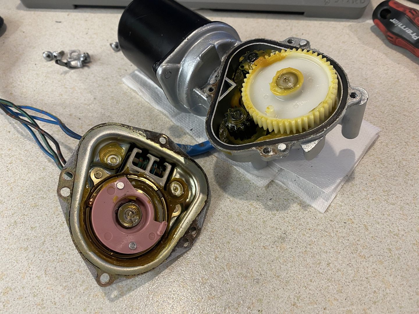
If you’re comfortable doing it, I suggest pulling the motor apart. They’re quite simple inside, and you can see exactly how the park contacts work. Basically, there is a rotating contact plate driven by the motor. When the wipers are parked, the park circuit changes state. When they are not parked, the park circuit is connected through the internal park contacts.
For PMU control, I prefer to reverse the motor polarity setup slightly. There is no issue doing this. The motor will spin the opposite direction, but because the linkage converts rotary motion to linear motion, the wipers still function normally. Just be careful with the linkage position when reconnecting everything. I suggest removing the wiper arms first and using tape on the linkage to watch the sweep direction before fitting the arms.
The wiring change I make is to remove the original red 12V feed from the park contact side and connect the motor-side common to ground instead. The easiest way is to cut the red wire at the park contact, terminate the motor-side wire with a ring terminal, and attach it to the same point as the main housing ground. The remaining red wire can be removed completely, and that park contact is left unused.
If you’re confident soldering, I recommend replacing the internal wiring altogether, especially on aftermarket replacement motors, as the wiring and soldering can be pretty average. Just remember to pot the solder contacts with epoxy or similar afterwards.
After modifying the red wire, you should be left with:
.
Black - Main ground for park contacts and common side of motor
White - Park circuit: grounded when not parked, open circuit when parked
Yellow - Slow wiper speed, positive switched
Green - Fast wiper speed, positive switched
.
On the PMU/PDM side, wire it like this:
.
Black - Good chassis/battery ground
White - Any analog input, e.g. Analog 1
Yellow - Output 8
Green - Any other output, e.g. Output 9
.
Output 8 is important because the ECUMaster wiper module uses that output for the low-speed/park/brake control. The fast-speed wire can be on another output.
For the park input, set the input as:
.
Type: Active high switch
Pullup/Pulldown: 10k pullup
.
With the modified wiring, when the wiper is not parked, the park wire pulls the analog input to ground. When the motor reaches the park position, the park circuit goes open circuit, and the PMU’s internal pullup brings the input high. That tells the wiper module the motor is parked.
At that point the PMU can turn off/brake Output 8, effectively applying ground/brake to the motor and stopping it from overrunning past the park position.
For the switch setup, you can use separate inputs for intermittent, slow, and fast, or a single multi-position switch.
If using three separate inputs, create a Number channel rather than a Function, because Functions are only true/false logic.
Example Number channel:
.
.
n_WiperMode =
choose(Int Wipe, 1, 0)
+
choose(Slow Wipe, 2, 0)
+
choose(Fast Wipe, 3, 0)
.
.
This gives:
All off = 0
Int = 1
Slow = 2
Fast = 3
Then set the wiper module’s Multiple Swipes Input Channel to:
.
n_WiperMode
.
In the Multiple Swipes table, set:
.
0 = Off
1 = Intermittent / delayed wipe
2 = Slow
3 = Fast
.
One important note: this assumes only one of the three switch inputs can be active at once. If two inputs can be active at the same time, the number channel can add them together and give the wrong mode. For example, Int + Slow would equal 3, which would look like Fast. A proper multi-position switch should avoid this, but it’s worth checking in live data before relying on it.
Alternatively, if using a resistor ladder or rotary switch, you could use one analog input with voltage thresholds instead of three separate switch inputs.
.
Any issues, let me know and I'll do my best to help out.
Thanks for that Caleb.
I will look into altering the wiring at the motor, basically changing it from a switched earth control to a switched live control and letting the park function operate from the PMU as it would with a more normal wiper motor.
I'll be using the stock Datsun rotary wiper selection knob, so it should not be possible to select more than one input. I am happy to create a number channel, since this is well enough explained in the course. The wiper control was another source of issue for me. With it left stock there is no way to get an individual signal for INT, so before I can use them, I need to create my own sliding contact plate.
Would my idea with using 2 relays and a timer to allow power to continue to the motor have worked? Just not as simple as changing the setup, and would have required 3 outputs instead of 2.
I am not at home for a bit to have a look at the motor, but I don't see why its not possible, I will let you know how I get on.
So. Its now the time this needs to be sorted, so I can finish my wiring harness.
Was hoping for some clarification before I wreck something.
.
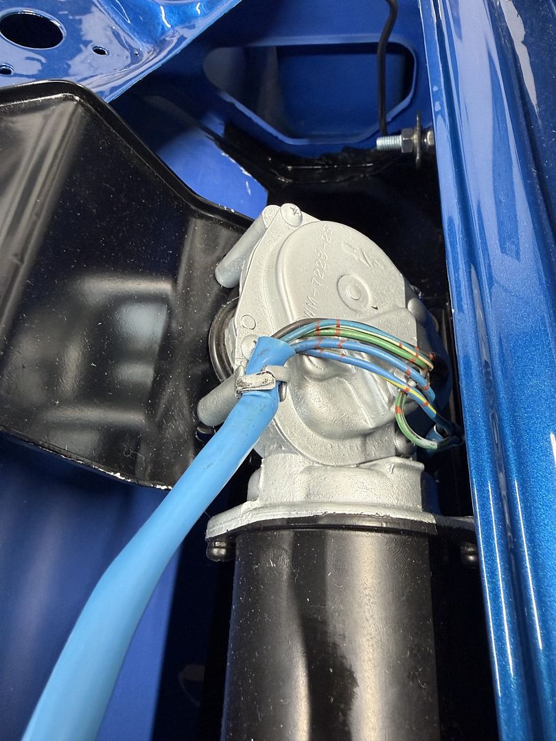
Here is my wiper wiring:
.
Currently wires are as follows:
.
12V - Green/Black
Park - Blue/White
Low - Blue (Earthed)
High - Blue/Yellow (Earthed)
Black - (Earth I assume)
.
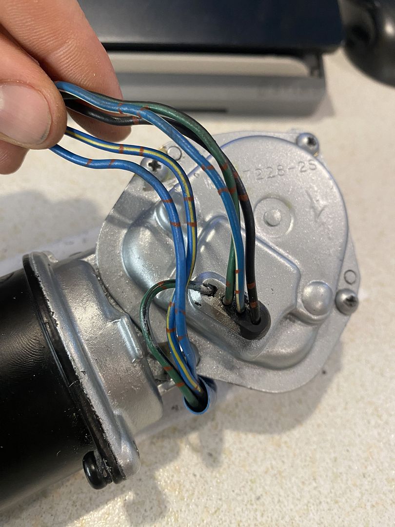
I can't see any way to alter my wiring internally, it not possible to open it up due to how it assembled. I can however re purpose the wires externally.
.
The plan would be:
.
Green/White = Park
Blue = Low (+12v)
Blue/Yellow = High (+12v)
Green/Black = Earth
Black = (Does this need connected to Green/Black)
.
My confusion is regarding the park switch setup. Since originally it would have been positive into one side, it is now earth, what signal will I get a the park switch? Where does the black (Earth) go? Can't get my head around it.
.
How do I get an appropriate signal at the park switch, can it be +12v or does it have to be earth?
Does the park signal come from the Blue/White or from the Black? Do I need both connected?
.
From my thinking, if Green/Black is now earth, then Blue/White should now be earth, but it will only show continuity when connected to Black when in the park position. Can this be used as a park signal? Or do I have to reverse the earth to a +12v on the black wire so when it completes a circuit through Green/Black that Blue/White shows either 0v or 12v?
Hey Ian,
The beauty of using a PDM/PMU is that it doesn't really mind whether the park switch changes to ground or 12V. At the end of the day, all it needs is a reliable change of state to know when the motor has reached the park position.
The confusing part is understanding what the park switch is actually doing.
A simple way to think about it is as an ON-ON switch that's operated by the cam inside the gearbox. The Blue/White wire is the common output of the switch. One side of the switch connects to the Black wire (Ground), while the other side connects to the Green/Black wire (12V). As the park cam rotates, it switches the Blue/White wire between those two connections. So for most of the wipe cycle the Blue/White wire will be connected to ground, then when the motor reaches the park position it switches over and is connected to 12V.
In the factory wiring, that changing signal is used to keep the motor running after you switch the wipers off until it reaches the park position. Once parked, the switch changes state and the motor stops.
Because you're using the PMU, it takes over all of that logic. It simply watches for that change of state on the park wire and decides when to turn the motor outputs on or off. It no longer needs the original self-parking circuit to do the work.
Before changing any wiring, I'd grab a multimeter and verify exactly what your motor is doing. Slowly rotate the gearbox by hand and check for continuity between the Green/Black and Blue/White wires.
If, as expected, the Blue/White wire changes continuity to the Green/Black wire only for part of the rotation, then I'd wire it like this:
If your continuity test gives different results, or you have any other questions post them up here before making any changes and we'll work through it together.
Thanks for the reply Caleb
I get continuity between Green/Black and Blue/White only when its in the park position. So this should function just fine.
That will let me wire the DT connector to the wiper motor and get my final engine bay harness made and installed. Great.


