La venta termina hoyObtén un 30% de descuento en cualquier curso (excepto paquetes)
Termina en --- --- ---
En esta sección, hablaremos sobre todo lo relacionado con el tuning . Noticias, productos, problemas y resultados.
M1 package and logged data here:
Vehicle and System Specifications
Engine: 2JZ 3.4L (94mm crankshaft, 9.1 CR, 3314.38 cc – (86.5×94×6)
Billet main caps, Manley Tri-beam rods, Diamond pistons
GSC Beehive springs, pocket port, shimless buckets, Tomei 264 cams (9.5 mm lift)
Precision 6466 Gen 2 turbocharger (.87 A/R), PHR S45 twin scroll manifold, 4” downpipe
Precision wastegates
FIC 1440cc injectors (14 mm, 64 mm length)
Aeromotive A1000 FPR, dual Walbro fuel pumps
Bosch DBW (0 280 750 473.1.0)
Motec LTC with Bosch 4.9 wideband sensor
150 PSI fuel and oil pressure sensors
Crank sensor 12x tooth , it has two cam sensors (single tooth pickup)
One cam sensor retained on my car and one is blocked off
you will notice the cam sensors are not used (inlet or Exhaust), the engine only runs the crank sensor only
Reading up , this is normal, simpler, robust, and standard practice for 2JZ-GTE (non-VVT)
Question --
This car setup is basic compared to modern standards , to allow me talk to a motec tuner , I want to know what questions to ask to ensure they getting the most potential out of the ecu?
For example , no boost aim table setup , just a set 1.4 bar, should I expect a boost aim table
Are they going to check the engine speed reference offset (crip test) , timing light
PID control setup for closed loop systems
What are the essentials I need covered to get the potential out of a modern vehicle based ecu
I did not go through the files and the more experienced members can also correct me if I'm wrong,
For the questions (ordered from 1 to 5)
1- You have to set your own expectations from the tuner (what options would you like, application you will be using the car for, power levels etc.)
2- Again, if you would like to have your car at multiple power levels, consider having separate boost aims (depending on your cars traction,gear, TPS, Swithced by driver request )
3- One of the most important steps before starting the car (fuel injection on) is to set the offset with a timing light. Considering that a timing mark is available to indicate TDC in the compression cycle. This will be the basis for your ignition timing and fuel injection timing.
4- PID is the basis for any closed-loop operation in many of the available MoTeC options. It is quite simple to understand (Propertional is the acceleration and is the fast action part, Derivative is for dampening/braking, and integral is the over time correction factor that attempts to zero out any errors between the set target and actual value.)
5- I would highly recommend that you complete the standalone course here and read the MoTeC 2015 Training conference seminar notes
First off - Your engine is not running off the crank sensor only - the cam sensor is assigned to engine sync.
There is a 5 position rotary switch assigned (well that's what's calibrated - positions 0-4) which is tied to the boost limit table - which will scale the boost control. at the moment there is only 100% and 0 set (gate pressure and boost control)
Outside of that, AD.wolf covered everything else.
Hi,
Thanks for the replies and assistance.
I’ve identified some major issues with my car’s calibration. The injectors are currently set to FIC 1000cc in the ECU dropdown, but the car is actually fitted with FIC 1440cc injectors (installed and tuned by the same individual). I’ve created the correct linearisation table in the attached firmware file, although it hasn’t yet been uploaded to the car’s ECU. As it stands, the car isn’t running well.
I’ve started working through the Motec webinars to build a solid understanding of the ECU setup and calibration process.
Cam Sensor
Sorry , Yes , I can see the UDIG2 Referenced -- this is starting to make sense
If I comprehend correctly , regards the Cam sensor
Inputs --
Universal Digital Input 1 -- UDIG1 -- Speed Reference
Universal Digital Input 2 -- UDIG2 -- Engine Synchronisation
From my understanding
UDIG1 is the Crank sensor
UDIG2 is the Cam Sensor
In the software, the crank sensor is always configured as Universal Digital Input 1 — it’s a fixed resource and doesn’t need to be manually assigned.
The cam sensor, on the other hand, can use a variety of digital inputs, so it must be assigned to the input being used.
What initially caused some confusion is that both inlet cam and exhaust cam position resources were set to “Not in Use.” I assume these are for vvti or VTEC type variable cam control systems
On the non-VVTi 2JZ, there are two cam sensors, but one is typically blocked off. I assume the ECU only requires one cam sensor for phase reference in this configuration. non-VVTi 2JZ from what I read , it is also common to just use the crank sensor
Question:
1) My engine is a 3.4L stroker (94mm crankshaft, 9.1:1 compression ratio, 3314.38cc displacement
– calculated from 86.5 × 94 × 6
Regarding the engine displacement parameter in the ECU: Would there be any noticeable impact if it’s set to 3300cc instead of 3314cc?
2) I am getting an intermittent
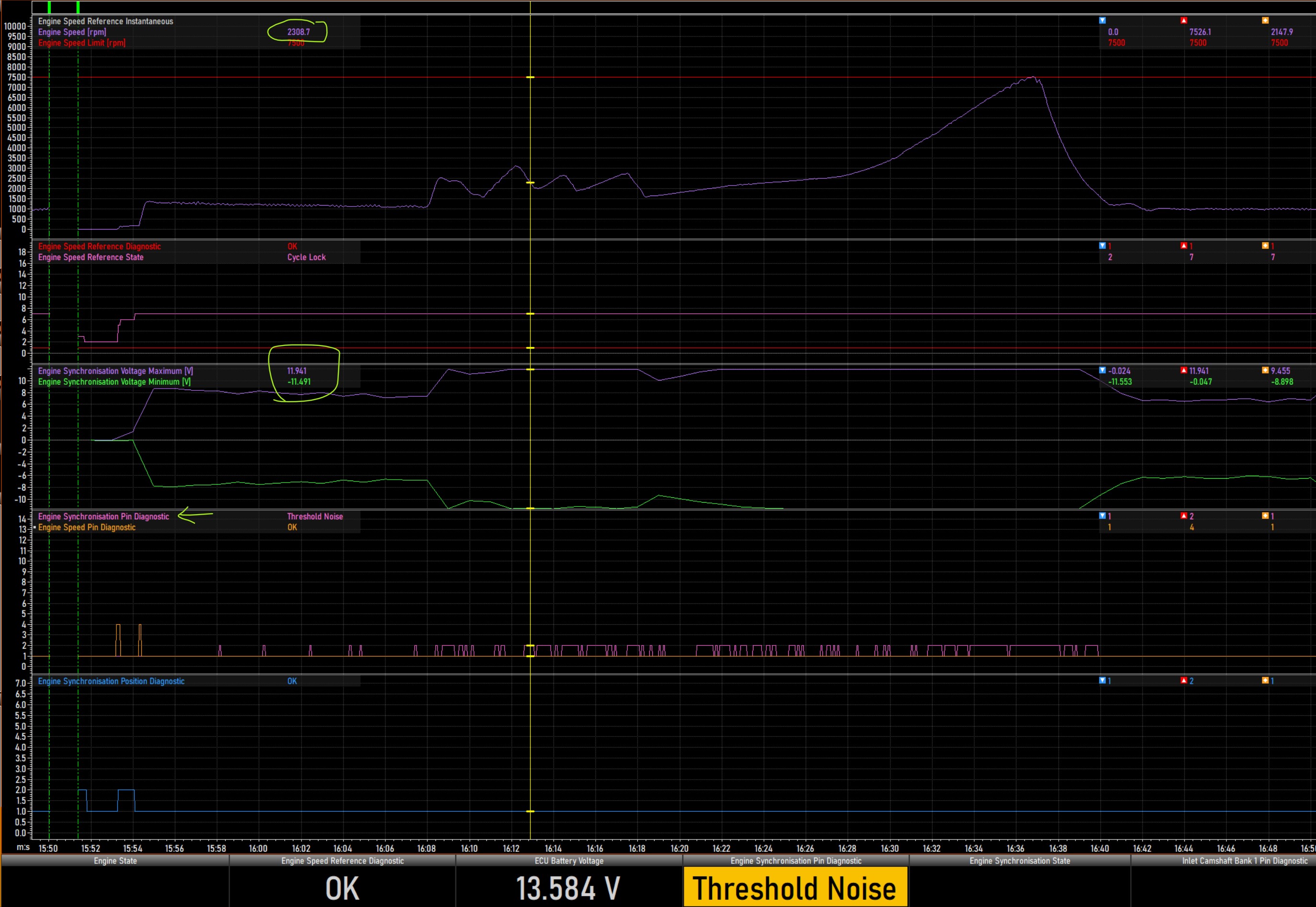
Warning -- Engine speed ref diag -- Noise
Noise
The reference input detected a tooth pitch below Narrow Pitch Threshold, indicating an edge has been missed or reference is not correctly locked to the pattern. The input falls back to searching for alignment with the reference pattern.
My Observations
OE Denso coils 6731200
Ignition driver current is set to 40 mA (Max value -- range 0 -40 mA) , Typically its 20 mA as per documentation
Eng Speed Ref Narrow Pitch Thresh is set to 50 , Motec Documentation suggests 60% (Motec webinars it is set as 50% , they are a few years old)
OE Crank sensor was tested , its within spec 1302 ohms cold
A trigger wheel with a lower tooth count is more susceptible to this fault ( mine is a 12 tooth)
Motec webinair says to leave these settings alone, wide, narrow pitch and blank ratio ; in future firmware updates , they will most likely be hidden
Am I in the right ball park
Similar issue on here , set the Eng Speed Ref Narrow Pitch Thresh to 60% and it resolved the Warning -- Engine speed ref diag -- Noise
Answers:
0. Regarding injectors, comparing the config from the logging to the one where you have changed the injector calibration (supplied calibration), there will be about a 12% difference (leaner) at idle fuel volumes (on the linearisation table) at the end of the linearisation table of the 1000cc calibration, the difference is 17.5% and the reference flow is 50% differed, so you can picture the difference is going to ramp up. This means your efficiency table will end up scaling up and have VE numbers more representative of the engines VE.
1. It will make about a 0.422% difference to the engine
2. These statements are not correct. You have very little engine speed (crank sensor diags). These would be affected by the engine speed narrow tooth threshold. The narrow and wide tooth thresholds are the accepted changes in crank tooth spacing before an issue is flagged. Changing from 50% to 60% would narrow up the acceleration margin. Your sync voltage reads to the limit of the ADC at 2000rpm.
The diag for this is the following:
A narrow pulse that crossed Threshold was rejected. This warning indicates the pulse width was more than 75% of Debounce and was close to being accepted.
Debounce may need adjustment. May also indicate a sensor or wiring fault.
I would add 50% debounce to the 2500rpm site at a minimum. I would also add more to the rest of the higher engine speed sites. You may also need to add to threshold voltages.
Regarding ignition driver current - this sets the strength of the pullup on the low side ignition. it doesn't do any harm having it set higher. In fact, if other functions using low side ignition resources are relying on the 6V on the low side resource, reducing it could impact this behaviour.
Thanks, Nathan — appreciate the help. I definitely owe you a beer.
From my comprehension, narrowing up the acceleration margin to 60% would mask the underlying issue
Looks like I need to spend a bit more time reading up on Engine Sync Pin/Speed Debounce, and I’ll test the cam sensor as well.
And your point about it making about a 0.422% difference to the engine — absolutely perfect. That’s a proper engineer’s answer if I’ve ever heard one.
Last question, the oe crank and cam sensor are Reluctor sensors, would the M1 benefit from a digital hall sensor? Both have plus and minus advantages
Have a great weekend!
Hi Nathan
I update the
Hysteresis -- as per MoTec Firmware help for magnetic sensors (0.2 V at 0 rpm and 2.0 V for the remaining 4 sites 1,2,3,4 K rpm))
Debounce -- I updated as per suggestion , at 50% , then to the max 130
Thresh is at 0 , Typically magnetic sensors use a zero volt threshold
The issue is still present ,
I also performed capture inputs
If you can point me in the right direction, greatly appreicated
These are settings another 2jzGTE with magnetic sensors uses , looking at the input captures and logs , I am try to establish if these settings are applicable to my car
Hi John,
Try this Debounce table. Extract the file from the zip file, then in M1 Tune, right click on the Engine Speed Pin Debounce table and select Import | From File, selecting the extracted file. This will automatically load the new table.
Thanks Stephen
It is the Engine Sync pin , it is in the screen shots Nathan added Sync-diags-2-v2.jpg
I will add and create the table on the Engine Sync pin debounce
Engine speed pin looks to be happy , I will leave as is
Out of curiosity, how did you land on these numbers , anything in the logs or capture inputs I can reference, just through experience?
Getting a couple of hundred engines up and running on M1's has gotten those values.
Both edges should be Falling.
Great thanks
Will update both
Hi Stephen
Engine sync pin is still failing , if I increase the 1K site to 130 it hitting an intermittent max debounce threshold
If I ramp up into the 2k site the threshold is triggered , set to 130 and it is intermittent
I did test both sensors , are are within manufacture spec
Setting any of the values in the Debounce table to 131 will trigger the Max Debounce warning, irrespective of the engine conditions.
Can you please supply the Package as well. You can mail it to MoTeC Support if you would prefer.
You are getting a Threshold Noise error on the Sync input, this is not showing in the input captures though. It looks like there is an external noise source that is causing a voltage spike on the Sync input.
Hi Stephen
It's here
https://drive.google.com/drive/folders/1B80lSPEqYEEjv3_hv4guEMDTOLmQQR7d
Was not aware 131 would trigger Max Debounce warning
Where did that information on the OE Crank Trigger come from John? The M1 does not generate a "Logical (Software) Wheel", a 12 tooth trigger wheel is a 12 tooth trigger with the angles calculated accordingly.
I got the information online , as you can see the firmware is locked to the non vvti 2jz trigger
I did not have visibility to the configuration to confirm how it was setup , hidden in my firmware
I will update my notes file, it is the plan is to get an experienced Motec Tuner to review at some stage


