La oferta termina hoy.Obtén un 30% de descuento en cualquier curso (excepto paquetes).
Termina en --- --- ---
En esta sección, hablaremos sobre todo lo relacionado con el tuning . Noticias, productos, problemas y resultados.
I was hoping to provide signal for my speedo from the ECU. Never got the speed input working correctly. So I just wired it straight to the speedo last time I was driving my setup (currently in rebuild stage) This worked great for the speedo, but ECU does not get input, which I guess I will need as I hope to setup reduced boost in first gear once its up and running again.
.
Easiest way to have both is to keep the output from the gearbox going to the speedo and then splice in an additional connector to also send this to the ECU.
.
So my question is, if were to do this, would it work, or would it mess up any chance of a clean digital signal?
I'd imagine earth could be the issue, but would probably be ok for the speedo, so earth for both should come from the ECU earth?
Am I better to just try and only supply the ECU and then use an output channel to supply the speedo, as I had originally planned? I believe this requires a +12v and a resistor to be added in, which I did last time, so I am assuming the actual output from the ECU was the issue.
.
If it helps, the gearbox is from an R33 GTS-T skyline.
What speedometer are you currently using? Some OEM speedos have a speed output that would typically go to an ECU or another body module (e.g., HVAC).
If this is not an option, there are modules that will modify and convert the speed signals. Typically these will have Single inputs and provide multiple speed signal outputs. If you need to convert the signal from your current speed sensor to your speedometer, this will help with that conversion and also give you an additional output to send to your ECU. Look up Dakota Digital SGI-100BT.
For nearly the same price as the above-mentioned VSS converter, you can buy an add on speed sensor for the transmission. This would typically be a more ideal solution for getting driveshaft or vehicle speed in a performance scenario.
Speedo was always working 100%. Using Speedhut gauges.
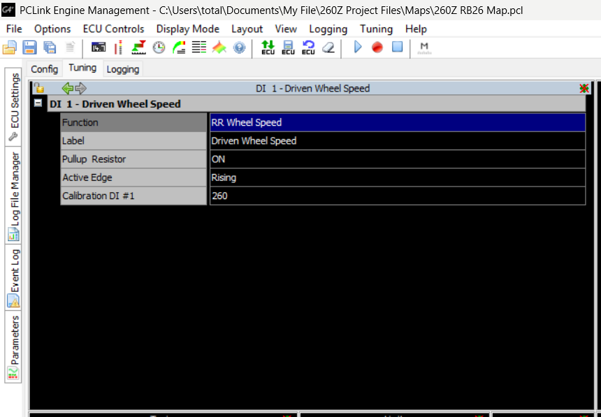
The only issue was I having is that since I had to wire it direct I was getting no feed into the ECU. Back then I didn't need it, but now I'd like to try and use some boost by gear tables. So I will need it.
Easy way at this stage is to simply splice two outputs into the speed signal output, so long as this won't disrupt a clean signal to either.
I don't reckon the ECU (Link G4+ Xtreme) would require any convertor, surely it can work from the direct analog input. I can't currently test anything, since I am still wiring the car, so I don't know if the issue was from the input to the ECU, or if the input was working fine and the output was the issue.
Once its all running again I can check. But I was thinking if I can splice in another output then it saves any hassle as the speedo continues to function properly without extra work.
.
.
Output from ECU to speedo should have worked like this, but never did.
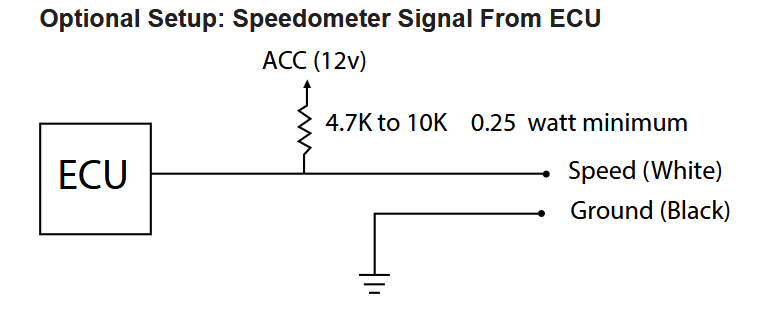
That diagram would assume the speed signal is an input on one set of pins and the ECU will output the speed signal on another AUX Low Side PWM capable pin. This is not sharing the speed signal, it is using the ECU to pass through and output a dedicated signal to the gauge.
Some ECUs are capable of this and some are not. To do this correctly, the ECU will need the ability to send out a variable frequency across a fixed duty cycle. This is not common for normal engine related outputs. For example, a boost control solenoid will work on a fixed frequency and a varying duty cycle. Typically the output will have a single value for frequency and the control tables will determine the duty cycle.
Understanding a little better what you had previously tried, You might want to flip the splice direction around. Add an external pullup from the sensor to 12V, as shown in the diagram. Then wire this signal to the ECU and speedometer. This way both devices will receive the signal.
Yes, nothing is currently spiced, I just had not been running the feed into the ECU. Since I had no need for the ECU to know the speed it was easiest to just wire straight to the speedo whenever I didn't managed to get the feed from the ECU to work with it.
.
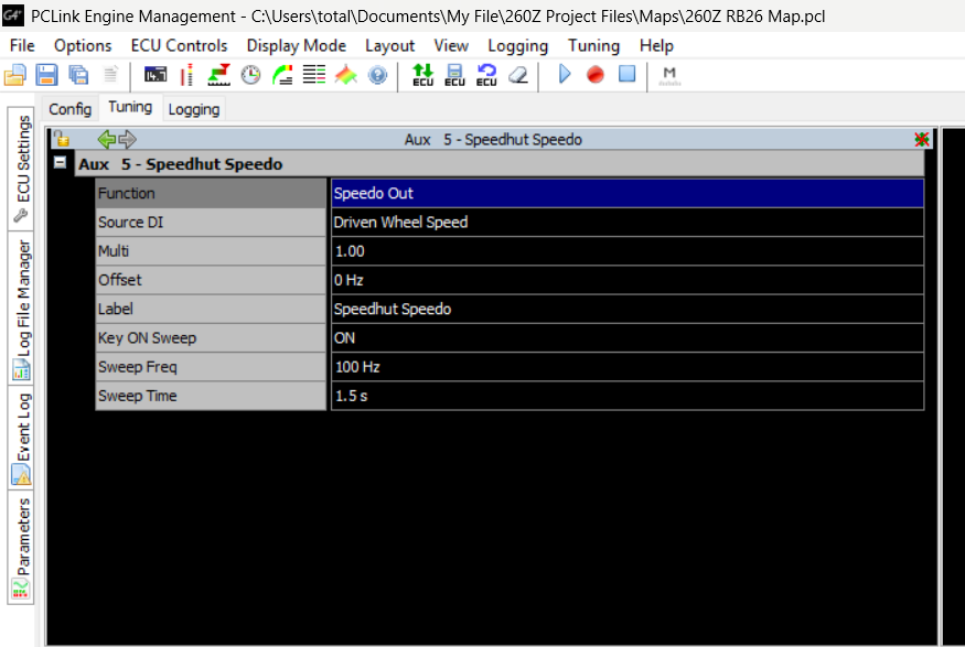
Best would be to connect the ECU plug, then get the output (Aux 5) to work correctly with the Speedo. The question about splicing is a backup solution if the output is not suitable to make the speedo work.
.
.
I did not have much knowledge back when I first did my swap. I may now be able to make it work without splicing in 2 connectors. However since I am doing wiring work currently. If splicing in a second connector, so it has one fro the ECU as well as one direct to speedo would cause no issues with the input signals then I see no reason not to do so, and save any hassle with another ECU output. So this is my main question here.
.
For the ECU side, It may be setup one for the feed or the output or both.
There should be no reason the ECU cant drive that speedo from an aux output. No pull-up resistor is needed as the ECU has a 12V pull-up internally.
Thanks, I shall just be patient ans wait until its up and running again, then try and get the input sorted, then the output should be easy also. And to clarify, you are saying that the external resistor is not required as I can set a pull up resistor for the AUX output in the software? How about the +12V spliced in?
To my original question, purely because I want to know for future reference. Since its a digital output, and not analog, splicing another connector in, would probably work? But could be a minor difference because of earth reference? For example, to the ECU, the earth would come from the the ECU earth output, so it can reference its own earth. But the one spliced into it for the speedo, would also have to read from the ECU earth source? But since the speedo can be set to any impulse reading, it probably wouldn't matter? Am I correct on these assumptions?
@EF Ian, the Speedo wants to see a High Side Square wave signal. If one is not available, you will use a Low Side output with the 12v/pullup. If a High Side output is available from the ECU. You will just wire that output directly to the Speedo input.
You should be able to bench test this with little effort. Just connect the single wire from the ECU to the speedo and manually set values in your ecu to see how the speedo responds. You will need to do this to confirm the Speedo calibration. The speedo will be a function of the ECU and will only be as accurate as the input speed calibration and the accuracy of the ECU to Gauge calibration.
Thanks for the info. Appreciate it.
I can set at the ECU, but also at the speedo. I may set at the speedo again. After a few attempts at setting I managed to get it to read the same speed as my GPS, so it was very accurate, at least between 60-80 where it spends a fair amount of time.
.
Looks like my older version of the G4+ does not support high side outouts. So I will require the external pullup.
"Since your Red and Black G4+ Xtreme only supports Low Side (ground switching) on Aux 5, you cannot directly send a 12V pulse to your speedometer. However, you can achieve this by using an external pullup resistor"
.
I will set it up and bench test it. I believe I can do this by changing fuction to 'test PWM'
"And to clarify, you are saying that the external resistor is not required as I can set a pull up resistor for the AUX output in the software? How about the +12V spliced in?"
You dont need the 12V or the external pull-up, there is already a pull-up internally on Aux 1-8, you dont need to "turn it on" in the software, it is always present.
"To my original question, purely because I want to know for future reference. Since its a digital output, and not analog, splicing another connector in, would probably work? But could be a minor difference because of earth reference? For example, to the ECU, the earth would come from the the ECU earth output, so it can reference its own earth. But the one spliced into it for the speedo, would also have to read from the ECU earth source? But since the speedo can be set to any impulse reading, it probably wouldn't matter? Am I correct on these assumptions?"
From memory the R33 speed sensor is a VR type - it outputs an AC signal. So splicing into one or both of the wires may or may not work depending on the circuit used to condition it inside the speedo. Some VR circuits use differential inputs, some use a ground reference.
"Looks like my older version of the G4+ does not support high side outouts. So I will require the external pullup."
"Since your Red and Black G4+ Xtreme only supports Low Side (ground switching) on Aux 5, you cannot directly send a 12V pulse to your speedometer. However, you can achieve this by using an external pullup resistor"
All of this is incorrect. To start with you dont need a highside drive at all, the ecu has an internal 1.5K pull-up to 12V on Aux 1-8. Connect the aux output directly to the speedo input with nothing else required. Aux 5-8 in the Red Xtreme in fact do have high side drives exactly the same as the black Xtreme, but in both cases they are only available for specific functions and it is not required for a solidstate speedo.
You would actually be better to use Aux 1-4 rather than aux 5 as 1-4 can do 4000Hz max whereas Aux 5 has a max of 300Hz. Although 300Hz would be enough for most speedos, the extra range of Aux 1-4 may be useful.
"You dont need the 12V or the external pull-up, there is already a pull-up internally on Aux 1-8, you dont need to "turn it on" in the software, it is always present."
That could be why it didn't appear to function the last time it was tried, as both of these were wired in. This makes the wiring much more simple.
.
"From memory the R33 speed sensor is a VR type - it outputs an AC signal. So splicing into one or both of the wires may or may not work depending on the circuit used to condition it inside the speedo. Some VR circuits use differential inputs, some use a ground reference."
Not worth trying that one out then. Thanks. This also gives me the benefit of two spare wires on my mini autosport bulkhead connector that my gauges are wired through, Could be very useful in the future.
.
"All of this is incorrect. To start with you dont need a highside drive at all, the ecu has an internal 1.5K pull-up to 12V on Aux 1-8. Connect the aux output directly to the speedo input with nothing else required. Aux 5-8 in the Red Xtreme in fact do have high side drives exactly the same as the black Xtreme, but in both cases they are only available for specific functions and it is not required for a solidstate speedo."
Fantastic information, thanks again.
.
"You would actually be better to use Aux 1-4 rather than aux 5 as 1-4 can do 4000Hz max whereas Aux 5 has a max of 300Hz. Although 300Hz would be enough for most speedos, the extra range of Aux 1-4 may be useful."
Good info, currently I can not do this, since Aux = Solenoid, Aux 2 = Fan, Aux 3 = Fuel pump, Aux 4 = Tacho. However since with my rewiring of the entire car, I'm moving to a PDM and most inputs to this will be via CANbus, that should free up both Aux 3 and Aux 2. So so long as I can get the setup working like I want I shall also plan to move the Speedo over to Aux 3.
.
Thanks a lot for the help, I really appreciate it, I'm now looking forward to getting to the stage where I can try all this out.


