183 | How a Relay Works
Summary
Relays are a great way of reducing the size of wire and switch needed to control a high power device. They allow us to minimise the size of our harness bundle, and used cheaper (but still high quality) switch gear for the control. In this webinar we will look at how a relay physically works, how we select one for use and how we wire it into the system.
| 00:00 | - Hi guys, welcome along to today's member's HPA webinar. |
| 00:04 | Really really great to have you along. |
| 00:06 | Today we're gonna be talking about relays, and as mentioned before, that may seem like a little bit of a dry topic, something that is reasonably simple to get your head around. |
| 00:17 | But there are actually some pretty in depth subtleties to the use of relays and they form such a critical part of our EFI system designs, the power supply side of our systems, that we really do need to have an absolutely in depth understanding of the different types that are available, how we use them and how to make the selections. |
| 00:39 | So the first thing we're gonna talk about is how a relay actually works and what a relay really is. |
| 00:48 | And to be honest it's all in the name, relay. |
| 00:50 | All it does is it relays a signal to another part of the system. |
| 00:55 | That means that we can use a much cheaper and lighter low current switch to in turn switch the relay which supplies a high current to our high power device that's needing it. |
| 01:11 | All a relay really is, is a switch that we actuate electrically as opposed to physically flicking the switch. |
| 01:20 | Now why do we use a relay? So as mentioned, it allows us to use cheaper, lighter duty switches in the interior of our vehicle that don't need to handle the entire load current of our large high powered device. |
| 01:36 | That is probably the key situation we're gonna be using a relay in. |
| 01:40 | It means we can run smaller gauge wiring to our actual switch that we're going to interact with and keep our large gauge wiring all much closer to the battery and the device that it's actually gonna be switching. |
| 01:53 | And that can end up saving us quite a bit of money and also quite a bit of weight, particularly if you've got a battery mounted in the boot of a vehicle, you don't wanna have to be running say a 12 gauge power wire up to a switch and then back down to the boot of the vehicle for something like a fuel pump for example. |
| 02:09 | There are a couple of other reasons that we might want to use relays, if we want to activate multiple devices from a single switch, it can be a really good way of doing it. |
| 02:19 | Particularly if those multiple devices are located at different ends of the vehicle. |
| 02:23 | Example of this would be say driving lights or fog lights on a 4WD vehicle, or a light bar, something like that. |
| 02:30 | You can have a single switch that actually actuates multiple relays that then in turn supply the high power required to the multiple devices that they're connected to. |
| 02:42 | Now another situation where we might want to use relays that's not completely evident at first blush is going to be to perform simple logical functions in a vehicle. |
| 02:53 | So when I say logical functions, I'm meaning "and" function or "or" functions and I'll just explain what I mean there because they're sort of more of an electrical engineering term that you might not be familiar with. |
| 03:04 | If we talk about an "and" function, that means that it's a function that has say three inputs and one output. |
| 03:13 | And that one output will be on, only when all three inputs are on. |
| 03:18 | Now you can have any number of inputs to an "and" function but it will only have the one output. |
| 03:24 | Now a situation where we might want that in automotive use would be an emergency safety switch. |
| 03:33 | Now this would be a relay that's supplying power to say the ECU of our vehicle and then we would have our low current switching side through a chain of switches, all connected in series. |
| 03:47 | So all of those switches would have to be turned on for our relay to then supply power to our EFI system, the ECU of the vehicle and keep the engine running. |
| 03:57 | You'd usually have one of these switches mounted in the interior of the vehicle for the driver to reach in an emergency, but it's often pretty common to have one on the exterior of the vehicle as well for a race marshall to be able to reach. |
| 04:09 | So simple logical functions like "and" and "or" are very easy to accomplish with relays and they can be really handy. |
| 04:19 | So now that we know why we're going to be using a relay, we should have a quick talk about how one actually works. |
| 04:25 | How we take that low current light wiring side of things and actually use that to control the high power side of things. |
| 04:35 | So I've set up a little bit of a demonstration here which I'll show at the beginning because it's gonna make what I'm talking about a little bit easier to see. |
| 04:42 | So if we just pop over to the cellphone camera quickly. |
| 04:45 | And once I've explained how this works we'll come back and we'll have a look at this again. |
| 04:50 | So this is just a simple setup, I've got some light gauge wiring, and you can see when I push on this switch part of the relay there is clicking back and forth and making contact between two different points. |
| 05:05 | Now that's probably not gonna make a lot of sense completely initially. |
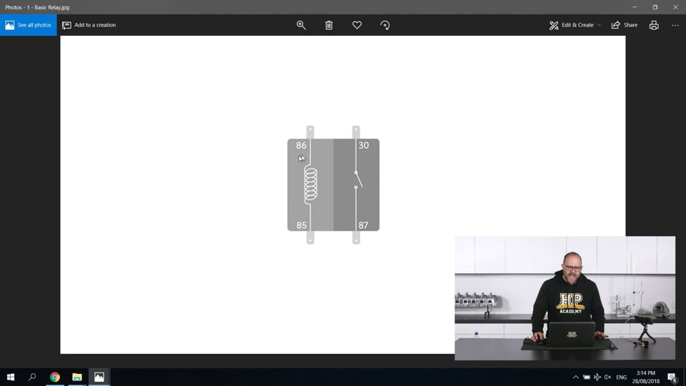
| 05:09 | So if we pop over to my laptop screen again, I'm just gonna bring up a diagram that Jono has drawn me here of a very simple relay and we'll have a bit of a talk about what's going on. |
| 05:20 | So your standard automotive relay is going to have four pins. |
| 05:24 | They're labelled, 86, 85, 30, and 87. |
| 05:28 | And I will completely agree with you that those numbers are actually a little bit odd and don't make much sense. |
| 05:33 | But they are part of an automotive standard and they're on almost every relay out there so it's definitely good to get familiar with them. |
| 05:40 | Now our 86 and our 85 pins here are connected to what is called our relay switching coil. |
| 05:47 | Now this is what we use our light gauge small current wiring to actually supply power to and it's actually a device called an electromagnet. |
| 05:55 | When we supply power to this device, it becomes a magnet and actually turns on the other part of our relay here which is our high power side. |
| 06:05 | So when we put 12 volts into the 86 pin and give the 85 pin a ground connection, it's going to close this switch here which was the clicking you saw on the relay and that is going to connect our high power input 30 pin to our high power output 87 pin. |
| 06:23 | Now that is probably around about the most simple implementation of a relay. |
| 06:30 | They have some other benefits. |
| 06:33 | We talk about the resistance of the coil, the resistance of that electromagnet switching coil is reasonably high and that's what means when we apply our 12 volts of electrical pressure across it, it is going to only draw small current, letting us use those small gauge wires. |
| 06:51 | Now an electromagnet coil as we talk about in the wiring fundamentals course actually is an inductive load. |
| 06:59 | And that means that as you are switching it on and off or particularly off, it's going to be generating inductive voltage spikes. |
| 07:07 | Now these can be particularly nasty things if they're getting into the electronic systems in your vehicle and they can cause all sorts of havoc. |
| 07:20 | They can radiate out noise and give you really unexpected sensor readings and even cause parts of your EFI system to switch on and off unpredictably. |
| 07:27 | Now we get around those inductive voltage spikes through the use of devices called snubbers. |
| 07:33 | So if we just pop back over to my laptop screen again here. |
| 07:38 | What a snubber does is it's a device that is connected between the 86 and the 85 pin here and it absorbs the energy of the inductive voltage spike that this coil generates when we switch it off. |
| 07:51 | So most commonly it's going to be in the form of a resistor. |
| 07:54 | And it will actually be included in the relay if it's an automotive relay. |
| 07:59 | It's very very tricky to find an automotive relay that doesn't include at least a resistor as a snubber in there. |
| 08:07 | There is another type that you will find where it actually uses a diode in here, in an arrangement called a flywheeling diode. |
| 08:16 | Now a diode is an electrical device, it's like a valve. |
| 08:19 | It lets current only pass in one direction. |
| 08:22 | So if we hooked up a diode to only allow current to pass in this direction, when we turn our relay coil off as that magnetic field is collapsing, the current can actually pass through this coil in a circle and sort of dissipate out reasonably harmlessly meaning we're not gonna get our big voltage spike on the 85 output here which is really what we're trying to avoid. |
| 08:49 | If you're using a relay that has a diode here, and they are actually really good things, I like to use them whenever I can, it does mean that the polarity of the wiring between your 86 and your 85 pins becomes really important. |
| 09:02 | If you put the power or the 12 volts of your system into your 85 pin and apply ground to your 86, the current is going to pass straight through that diode and it's like a dead short to ground. |
| 09:13 | Something that's probably going to let smoke out. |
| 09:17 | So that does mean we have to be very careful when we're using a relay like that that we have the 12 volts connected to our 86 and the 85 is our ground side and we are normally switching on that ground side there. |
| 09:33 | So we'll just have another quick look at that demonstration because now that we've talked about the different pins on the relay, we should be able to make a little bit more sense out of what's going on here. |
| 09:44 | So the big copper coil of wire there that you can see, if I can get things in focus here, is actually our electromagnet. |
| 09:52 | And I've got my wires here, I've got 12 volts going into one side of that electromagnet and when I press the switch it provides a ground and lets the current flow through that electromagnet. |
| 10:03 | And what that in turn does is it pulls this switch here magnetically and this contact point up here actually makes the connection between that 30 and that 87 pin. |
| 10:19 | I find seeing them in action is really a really good way of completely clarifying how a relay actually works and leads us onto a couple of other factors that we need to be careful of when we're using relays which we will have a little bit of a talk about later on. |
| 10:37 | Now there are lots and lots of different relays available in the automotive realm. |
| 10:43 | And I've got some pictures to show here of some sort of standard footprint types. |
| 10:49 | These are the most common types of relay that you're going to strike. |
| 10:53 | So if we're just on my laptop screen there, this is one of the most common relays you're going to see, it's just a standard automotive relay as it's called. |
| 11:02 | We've got our 86 and our 85 pins, our 30 and then our two output pins. |
| 11:07 | Often relays have two output pins just to make it easier to connect multiple devices to them. |
| 11:13 | Now that brings us to another quick point we'll just have a talk about, is there are different types of relay you can get. |
| 11:19 | The standard type we've looked at here, and the one I've got the picture of there are what's known as a standard normally open relay. |
| 11:27 | That means when they're sitting there with that electromagnet coil unpowered, the connection between pin 30 and the 87 pins is broken, as in we need to apply power to that electromagnet coil to make the connection between pin 30 and 87. |
| 11:43 | The inverse of that is known as a normally closed relay. |
| 11:46 | That means sitting there at its default state, there is going to be a connection between pin 30 and pin 87. |
| 11:52 | When we apply power to that switching coil it's going to break that connection. |
| 11:56 | Then there's also the intermediary between those which is a changeover relay. |
| 12:00 | Now that has a 30 and an 87 pin, but also another pin called 87A. |
| 12:05 | By default sitting there the connection is being made between pin 30 and pin 87, then when we apply power to our electromagnet switching coil, it's actually going to swap the connection over and pin 30 is now going to connect to pin 87A as opposed to 87. |
| 12:25 | So that's an awful lot of pin numbers to actually just throw around. |
| 12:29 | I really hope that made a bit of sense and clarified the different types of relays that you're gonna strike in the automotive world. |
| 12:35 | If we just pop back over to my laptop here, we'll go through a couple of the other footprint types you're gonna strike. |
| 12:43 | So as we mentioned, this is the standard automotive relay. |
| 12:46 | This is what's known as a micro or a standard micro relay. |
| 12:51 | I've particularly seen these used on Holden vehicles. |
| 12:54 | Exactly the same functions, you can see we've got all our same pin numbers, just a different format again, much smaller case, they're probably about half the size of our standard automotive relay. |
| 13:05 | You can still get them in a pretty high current rating so this relay is capable of switching up to 30 amps. |
| 13:11 | Moving on from there we actually get smaller again, and I'm sorry these pictures are not showing fantastic scale. |
| 13:17 | But this here is probably about 2/3 of the size of a micro relay, and it's what's known as an iso 280 micro relay. |
| 13:24 | So these have become more and more prominent in new vehicles being developed, particularly European vehicles use relays like this almost exclusively, for a couple of reasons. |
| 13:37 | They're just more compact, they're cheaper to produce, and they only come in fully sealed variants as well. |
| 13:44 | And the one step down from that again is what's known as an iso 280 ultra micro relay. |
| 13:50 | And this is about half the size again. |
| 13:53 | You can see our pins are closer together and just means you can fit more relays into a compact space, which when we're building the power supply system for a vehicle, it can actually become a really big issue. |
| 14:06 | If we're using standard automotive relays, mounting say the five relays we might need for a common system can actually become a little bit of a headache if it's in the interior of the vehicle as they do take up quite a bit of space. |
| 14:19 | Now speaking of mounting there, we'll have a quick talk about different ways to mount relays and what you should be looking for when you're deciding how to mount them in the vehicle. |
| 14:30 | First example we'll talk about is that standard automotive relay again. |
| 14:34 | And just popping over to that cellphone camera, we'll have a talk about the mount that I've used here. |
| 14:39 | So this is what's known as a standard relay mount. |
| 14:42 | You can see it's got a single bolt hole on the back and if you get multiples of these, you're capable of actually stacking them together and your relays do just clip into them once you've got your terminals. |
| 14:55 | But as mentioned, once you get five of these in a row they do actually get quite long and it can get a wee bit tricky to find space to mount those tidily in the interior of a vehicle. |
| 15:06 | Very similar to that for our standard automotive micro relays, you can get a similar looking mount, commonly available also stacked together and they do actually stack with these larger relay mounts as well. |
| 15:20 | And they can help you save that little bit of space. |
| 15:23 | Now there is another step up from that again and if we just pop over to the laptop screen one more time. |
| 15:31 | This is a product that I haven't actually used yet but I'm really looking forward to using and this is a general purpose mount for iso 280 relays. |
| 15:40 | And the way they work is that these pin spacings will match up both our iso 280 micro relays and our iso 280 ultra micro relays, that we showed pictures of before, but their pin spacing also matches up to a standard mini blade fuse. |
| 15:57 | And that means in our single plug here we can plug in a relay and we could put maybe two fuses in there to protect different circuits and then configure our wiring coming into the back of the plug so then we've just got one simple solution here with our relay and our fuses in place. |
| 16:13 | These are made by a company called GEP and I have actually ordered a few different types as they're going to be used in our practical wiring course and I'm really looking forward to getting some experience with them. |
| 16:25 | They come in much larger sizes with more pin locations as well. |
| 16:29 | So you can actually build quite a complicated power distribution setup in a really nice tidy way with those. |
| 16:40 | When it comes to choosing a location in the vehicle for our relays, you have to put quite a lot of thought into that. |
| 16:47 | The primary consideration is probably going to be the length of high power runs and keeping moisture out of the relays. |
| 16:56 | The standard automotive relay that we've looked at here, obviously is not completely sealed because I've been able to pull the top off it to show its inner workings. |
| 17:04 | And for that reason, a relay like that, I'd only ever wanna mount in the interior of the vehicle where it's not going to be subjected to moisture. |
| 17:14 | That being said, I'd probably never actually mount a relay like that one. |
| 17:17 | I would've chosen a completely sealed standard automotive relay which are pretty easily and cheaply available. |
| 17:23 | They're actually kind of getting hard to get, a relay that you can still open. |
| 17:28 | I had to do a little bit of hunting around to find this one here that I could pry apart to show the inner workings of it. |
| 17:35 | When you're choosing where to mount your relays you will always wanna make sure that they are mounted right side up. |
| 17:41 | So that would be with our relay here up in this direction. |
| 17:45 | And the reason for that is if it's upside down, any moisture that's going to collect is going to be able to drain down through our terminals into it, or even just sitting there on our terminals is possibly likely to cause corrosion which is not gonna be ideal. |
| 17:58 | The same is gonna go even if we're using that GEP relay housing that we had a quick look at there. |
| 18:07 | As although they do say they are a fully sealed unit, I still am gonna wanna mount one of those right side up to mean any moisture's going to drain away. |
| 18:18 | Heat, heat is going to be a big issue when we're mounting our relays. |
| 18:22 | As you can see there's a lot of plastic here. |
| 18:25 | Everything I've seen is really only rated to around about 85 degrees celsius maximum. |
| 18:32 | So you're gonna wanna keep them out of the engine bay if possible, or if they do have to be in the engine bay then you wanna keep them definitely shielded away or far away from any heat sources. |
| 18:42 | They really will actually melt pretty quickly just from radiant heat from the exhaust which is not something you're going to want. |
| 18:51 | Now with our standard relays here, all they types we've looked at so far are mechanical switching devices. |
| 18:58 | They've all got he electromagnet coils inside them which are making that actual mechanical switch motion. |
| 19:03 | And that means they are going to be subject to wearing out over time. |
| 19:07 | A standard relay like this is probably going to be rated for more than 100000 switching cycles I would say. |
| 19:15 | So it's probably going to be fine for the life of the vehicle. |
| 19:18 | However what does tend to kill them reasonably quickly are harsh vibrations. |
| 19:24 | This means when you're mounting them you do wanna take that into account, possibly use a little bit of rubber or a conreel mount, something like that to give them a little bit of isolation from vibration. |
| 19:34 | If they're getting rattled once something gets into a natural frequency or a harmonic, the relay can actually be rattled enough to switch it on and off, very very rapidly you'll get a lot of sparking going on inside it, and that'll wear contacts away quickly and really cause you a bit of grief. |
| 19:54 | Right so we've talked about the different types of relays and how we're gonna mount them. |
| 19:58 | We'll have a quick talk about how we're going to choose the type of relay that you're going to need to switch a high powered device. |
| 20:04 | The most critical factor it's going to come down to is the current requirement of your high power device. |
| 20:10 | So if we were talking about switching a fuel pump or a cooling fan, fuel pump, typically a high power fuel pump, something like a Walbro 255 probably going to be drawing around, between 10 and 15 amps when it's really working hard. |
| 20:23 | So with that factor in mind, we could choose a relay that's capable, I would choose a relay that's capable of switching up to about 30 amps, for that application just to give myself a really good bit of head room there and know it's gonna be nice and reliable when it's switching the pump under demanding conditions. |
| 20:40 | Same being said for our cooling fans, between actually I'd probably go a little bit larger for a cooling fan, between sort of 15 and 20 amps can be a reasonably common current draw for a high power cooling fan. |
| 20:51 | The other thing with a cooling fan is they actually take quite a bit of time to speed up and while they are speeding up, they're subject to an in rush current condition, it's just part of dealing with that motor is that while it's speeding up, when you initially turn it on it actually draws a much larger current while it's getting up to speed, so we want our relay to be able to handle that for the short time that it is going on so I'd probably use around about 40 amp capable relay for a cooling fan in a vehicle. |
| 21:21 | So next we're gonna have a quick talk about the next generation of relays that are getting commonly used in performance automotive applications these days and that's solid state relays. |
| 21:32 | We're not gonna go into them in a huge amount of detail, simply because it is actually a pretty in depth topic and probably deserves a webinar completely of its own, which I will make sure I add to the webinar list and will get done in the future. |
| 21:44 | If you've got any questions about anything we've talked about so far, now would be a really good time to start throwing them up in the chat section and the guys will fire those through and once we've talked about solid state relays we will get onto the Q&A. |
| 21:58 | Right so solid state relays, first thing we need to talk about is how are they different from our standard mechanical relays? It's once again all in the name, solid state. |
| 22:08 | So that means they're no longer a mechanical device, they're a completely solid device that has no mechanical switching components. |
| 22:16 | All their switching is done with electronics. |
| 22:19 | Particularly IGBT transistors are a really common, really commonly used in solid state relays. |
| 22:25 | That gives us quite a few benefits. |
| 22:27 | They're going to be, in the long term, much more reliable. |
| 22:31 | They are easier to protect from our, sorry they're not going to generate our inductive voltage spikes on the switching side as they no longer have an electromagnet switching coil. |
| 22:44 | So those are a couple of really good benefits. |
| 22:46 | Also we're able to turn them off and on far more quickly than we are with a mechanical relay. |
| 22:55 | When we're dealing with a mechanical relay, there's actual physical movement going on there and things take time to move back and forth, all the parts are building up and releasing momentum, and you really can't switch them on and off that quickly with any reliability. |
| 23:11 | Now that's not the same for a solid state relay. |
| 23:14 | Because all the switching is done electrically, you can turn them on and off very quickly. |
| 23:20 | And where this comes into its own is where we want to provide a speed control to a motor, something like a fuel pump for example, we can actually give it a pulse width modulated signal using our solid state relay because we can switch it on and off fast enough. |
| 23:34 | Something in the realm of 200 hertz would be pretty common for a fuel pump, so that means 200 times a second we are switching the power to the fuel pump and then switching it off again. |
| 23:45 | And we vary that on to off ratio time to vary the amount of power that we are supplying to our fuel pump. |
| 23:54 | Now when we get into solid state relays, there are a couple of different footprint options, so just popping back over to my laptop again quickly. |
| 24:03 | This is a really common one here that you see in a lot of installations. |
| 24:07 | It's got the same footprint as our standard automotive mechanical relay, but it is a solid state device. |
| 24:13 | Now you can get yourself into a little bit of trouble with these relays because they may or may not be completely pin swappable with a standard automotive relay. |
| 24:26 | If the standard automotive relay is having its electromagnet coil switched on the low side, and that means it's having power applied constantly to one side of the coil and then ground supplied to the other when we want it to turn on, then yes you can swap one of these relays into its place. |
| 24:42 | If you are sending 12 volts to the switching coil of the electromagnet relay, when you would like it to provide the high power to the device it's connected to, then no, one of these relays is probably not going to work in that application. |
| 24:57 | Next up we have a probably more commonly seen solid state relay in an automotive application. |
| 25:04 | These have screw terminals on them. |
| 25:06 | We've got our low current side here, which can accept a voltage of anywhere between three and 32 volts. |
| 25:12 | So that actually gives us an awful lot of flexibility there if we were building a device for a 24 volts system, and although this says 25 amps, 240 volt AC, you can actually still use it for a 12 volt, or 24 volt DC application. |
| 25:30 | To be honest, I don't particularly like to use this style of relay if I can avoid it as I find it can be really hard to get a nice tidy install with the screw terminals at all four sides. |
| 25:43 | It can be hard to mount them on a panel and actually have them look really nice and integrated. |
| 25:49 | While I was doing a bit of research for this webinar, I came across these iso 280 format relays which are a solid state relay. |
| 25:57 | And I couldn't resist, I've ordered a couple, they're on the way. |
| 26:00 | 'Cause I'm really looking forward to having a bit of a play with them. |
| 26:02 | As they also have, they're a completely hot swappable solid state relay in the iso 280 format but they also have some CAN bus outputs that you can use to turn them on and off. |
| 26:16 | Also with getting current draw information out of them. |
| 26:20 | And I think that is pretty awesome so I'm really looking forward to having a wee play with those. |
| 26:28 | Just popping back to my laptop again for a second, we'll have another talk about this style of relay here, and in fact the Hella ones as well. |
| 26:36 | One of the other benefits a solid state relay gives us is isolation. |
| 26:42 | And when I say isolation, I mean it's taking our low current switching side, so that is if our ECU is using the low current side of the relay to turn on the high power side which might be powering the fuel pump, or if our low current switch is connected there, that is now going to be completely electrically isolated from our high power side. |
| 27:03 | Now it does this with some internal electronics here. |
| 27:07 | It's called optical isolation. |
| 27:09 | And that means when you apply power to our switching side here, it actually lights up an LED, not this red one here, but an LED that is completely encased inside this device. |
| 27:19 | The light from that LED is then read by the rest of the sold state relay, and that actually gives the signal to turn on the high power side of the device. |
| 27:29 | Now that completely decouples the low power and the high power side electrically. |
| 27:35 | They've now got an optical coupling between them. |
| 27:37 | And that can be really important in some forms of racing where that isolation might be required, particularly if you're getting into electric vehicle realms. |
| 27:45 | One thing it does mean though is that extra stage of electronics in there can actually slow down the speed that we can switch our solid state relay at. |
| 27:55 | And for this reason when you're using solid state relay you're gonna wanna make sure you get really reliable and valid data about it, as it will have a maximum switching speed listed there. |
| 28:07 | For your standard screw terminal type relay here, it's typically I've seen around about 200 hertz is the maximum switching frequency. |
| 28:15 | If you try to switch them faster than that it might actually work initially, and you might only find the problem once the system actually gets under a little bit of load. |
| 28:27 | What'll be happening when you try and switch that relay a little bit faster is the relay will constantly be in a state where it has current passing through it but also a voltage across it, that means it's a dissipating power and it's going to heat up. |
| 28:42 | Which is something you really want to avoid. |
| 28:44 | I've definitely seen screw terminal type relays like this killed when switching things like electric power steering pumps for example. |
| 28:52 | You might want to pulse width modulate control an electric power steering pump. |
| 28:57 | You find when you first do it, when you have a switching frequency of 50 hertz, the motor's very noisy, you keep upping that frequency and the motor gets quieter and quieter and runs nicer and nicer. |
| 29:06 | Eventually you've settled on 500 hertz and everything seems fine, but the moment you actually get the car out on the load and the power steering system gets loaded up and that motor starts drawing quite a bit of current, that 500 hertz becomes a real downside and that relay gets very hot, and lets it's smoke out pretty quickly. |
| 29:24 | So that's something you want to avoid if solid state relays are going to be a way you're going to want to go. |
| 29:33 | Rightio, so that's brings us to the end of our talk about relays today. |
| 29:38 | As I said, relays can be a little bit of a dry topic but I really hope that it's given you a bit of insight into their operation and really clear understanding of why we use them and when we use them, as they do form a completely critical part of the correct power supply system set up when we're building an EFI system. |
| 29:58 | So we're gonna jump into some Q&A now. |
| 30:02 | So had a question from Andy actually right before the webinar began which I thought was really really good, so I've thrown it in here. |
| 30:08 | What happens when you PWM switch a standard relay instead of it being a solid state relay? And we sort of touched on this a little bit in the webinar when I talked about vibration. |
| 30:23 | If you try and switch a standard relay on and off very very quickly, it's like it's getting vibrated very hard and that switching coil is actually going to flick back and forth quickly, generating possible sparks in there, and it's much like the situation you get with an old points ignition set up where those points end up wearing away and the wee contact buttons in the relay actually end up wearing away and it's not going to be relaible at all. |
| 30:52 | You're also getting to a situation where the relay will either just not turn on or it will turn on and then it will not turn off again, if you end up switching it too fast. |
| 31:03 | Anything faster than probably about five hertz. |
| 31:05 | Actually even five hertz is probably getting a bit quick. |
| 31:08 | Maybe anything faster than about two times a second, I would definitely be looking to use a solid state relay as opposed to a standard mechanical automotive relay. |
| 31:19 | The other downside of trying to PWM switch a standard mechanical relay are going to be those inductive voltage spikes. |
| 31:26 | If we're not protected against them, you're gonna be generating an awful lot of them and that has the possibility of inducing quite a lot of noise into your electrical system. |
| 31:36 | Craig has asked, what sort of materials would you be looking for that make up quality relay contact materials, and magnets? Right the contact materials I'm actually not too sure on that one, that is a really good question. |
| 31:53 | I suspect a little bit of a google research there is probably going to, a little bit of a google there is probably gonna find the most common material used for those contact buttons. |
| 32:02 | The magnet inside them is going to be a reasonably standard sort of solenoid or electromagnet arrangement where it's gonna have a ferrite core down the middle and that copper winding around it. |
| 32:13 | It's pretty old technology now and I'd say even the cheapest relays on the market are going to have pretty high quality electromagnet coils in there. |
| 32:21 | But the contact buttons there could actually be worth looking into. |
| 32:27 | Craig has asked, can you use two relays to deliver twice the current if a higher capacity relay is unavailable? Yes but with some caveats. |
| 32:37 | Because they are a mechanical switching device, you're going to find that if you provide the signal to the electromagnet coil, to two relays at the same time, one of them is inevitably going to turn on fractionally faster than the other and for that fractional period of time, it is going to be carrying the entire current of the system. |
| 33:00 | Now if you're switching something like a motor which is going to have that large in rush current, then this could actually get you into a situation where that tiny amount of time that single relay is passing all the current, might be enough to actually heat the contacts up enough to fuse them together. |
| 33:17 | So I would say that if you're switching a resistive load, it's probably going to be OK, but I probably wouldn't use that technique in a situation where you're switching an inductive load like a motor. |
| 33:29 | There are some pretty high power relays on the market now. |
| 33:32 | You can get ones in a relatively standard form factor, it's like our standard automotive relay here but a little bit bigger and they can handle up to 200 amps which should probably be capable of any current you're going to be switching in an automotive sense. |
| 33:48 | Of course excluding the starter motor current which could be much larger than that, but the starter motor's typically going to have almost its own relay device built into it in the form of the solenoid and plunger. |
| 34:01 | Butterfly has asked, hi guys it's nice to catch you live, I have a question, what's the safety protocol in relays? Do they fail automatically with slight degeneration? Something for a defect like the offset seat when switched off. |
| 34:19 | So I think what you're asking there is what sort of failure modes can we expect when a relay is going bad? And I've actually seen relays fail in many ways, I've seen them fail so they're on all the time, I've seen them fail so they'll never switch on and they're off, and I've seen them fail where they will continually switch on and off back and forth and that's typically seen by a really annoying buzzing coming from under your engine bay and you'll narrow that down pretty quickly as it's quite audible to the relay in question. |
| 34:48 | Particularly OEM style relays that might be getting a bit old and have been subject to many heat cycles in the engine bay. |
| 34:55 | Quite often you can see them develop that dreaded death buzz. |
| 35:01 | Dylan Lange has asked, what if I have to run two separate fuel pump relays from a lower current relay using your ECU as your 12 volt switch, 86 for both, should I splice a bigger gauge wire into that switch 12 volt wire for the second high current relay? I know I have to tie them both together by the battery voltage. |
| 35:25 | The second one is the higher current. |
| 35:28 | So I'm not 100% certain what you're asking there but I can think of a couple of different things we might be talking about. |
| 35:35 | If you're having to run two relays from a single switch then no you're probably not going to have to run a larger wire from that single switch to the two relay switching coils as they do typically draw in the realms of 100 to 200 milliamps only. |
| 35:51 | So standard 22 to 24 gauge automotive wiring is more than capable of supplying the power to those two switching relays. |
| 36:01 | The other situation we might be talking about there is if we are installing an auxiliary relay in a vehicle and using an existing relay to switch it. |
| 36:13 | This is commonly seen when you're doing a fuel pump relay upgrade which is pretty common for 90s to 2000s Japanese vehicles where the standard fuel pump relay and standard fuel pump wiring is really not up to the task once you install a higher current draw fuel pump and you end up with a lower voltage seen at your fuel pump and it can't actually supply its full output potential. |
| 36:40 | So what we do there is we run extra higher current, higher capacity power wiring from the battery to another relay that we mount usually in the boot near the fuel pump which then heads down to our fuel pump and that larger power wiring can handle the extra current requirement of our upgraded fuel pump. |
| 37:03 | We then use the original output from the fuel pump relay to switch the switching coil on that additional relay that we've put into the system. |
| 37:13 | In that situation the existing fuel pump wiring that is coming from the existing fuel pump relay is gonna be absolutely up to the task of switching the solenoid coil on our additional relay that we've added into the system. |
| 37:29 | Andy has asked is there a relay board that I like? Say five or six relays in a set? Off the top of my head, traditionally I've actually used the relay mounts that I've got here. |
| 37:44 | I do like that they slide together and they've got a screw hole, and they are quite nice and easy to mount. |
| 37:49 | However I am really looking forward to getting those GEP relay plugs and using the iso 280 style relays. |
| 37:57 | As I think it's actually gonna be a much more integrated way to go and I'm really really looking forward to getting into that and being able to get all your fuses in that same package as well, is just gonna make everything nice and tidy. |
| 38:09 | There'll be one wiring trunk that'll come up to that board and you won't be able to see any of the connections in behind it so it's gonna be a really good way to go. |
| 38:18 | Spiderman or Peter Parker has asked again, are you a fan of, or do you endorse automotive relays with built in fuses? No I'm not a fan of them and I don't endorse them because I've actually had them fail on me more than one time. |
| 38:30 | And it is generally because of moisture ingress problems. |
| 38:34 | I remember a particular example that springs to mind is on my Mitsubishi Starion. |
| 38:40 | I had a couple of relays with in built fuses that were switching some additional cooling fans that I'd put in, and I had mounted them in the engine bay up the top, I though they were actually gonna be OK up there, but over the following years they did see a little bit of moisture and because they've got those terminals on the top of the relay where you actually plug the fuse into, I had some corrosion issues there and things actually got pretty hot and because of the corrosion giving a high resistance there, and the relay bodies melted and resulted in the cooling fan failure which resulted in a slightly overheated engine. |
| 39:14 | Wasn't any damage in the long run but no I'm definitely not a big fan of the automotive relays with the fuses in them. |
| 39:23 | Shaun Sweet has asked what about SSR relays, when do they go bad, any similar issues? I've never actually had a solid state relay fail on me when it's being used under correct conditions and when it's sized properly for the system. |
| 39:35 | When we talked about those I did talk about a situation with a power steering pump that was being pulse width modulated controlled with a solid state relay and that relay certainly did fail in a pretty spectacular fashion actually, it resulted in far more smoke than you think a package that small could actually even contain. |
| 39:55 | But that is because it was being switched far too fast. |
| 39:58 | The customer had set the PWM switching frequency up to 500 hertz because everything sounded great when the car was sitting there with no load on the steering system. |
| 40:07 | But when it was out on the racetrack, that resulted in a brown trouser moment cause there was a lot of smoke and it was a little bit tricky to see what was actually, where it was actually coming from. |
| 40:18 | But no I've found solid state relays to be really reliable. |
| 40:21 | I'd say if there were going to fail, they're probably going to fail in a normally open mode, just because of the type of insulated gate bipolar transistors or IGBTs that they have in them, that is their typical failure mode. |
| 40:35 | Shaun Sweet has asked, can you get iso 280 relays with high load capabilities? Also the highest solid state relay loads. |
| 40:44 | So the iso 280 relays, the highest current rating that I've seen on those is 25 amps. |
| 40:50 | And for most automotive situations, that is going to actually be fine. |
| 40:54 | Solid state relays, I can't actually think of the highest load rating that I've seen on those but I wouldn't be surprised if you could actually get them up to in the 50 to 60 amp range in the screw terminal type without any issues, as they're a reasonable large package, there's quite a lot of space in there to fit extra transistors in, to get that extra current handling requirements. |
| 41:20 | Rightio that's brought us to the end of our question and answers. |
| 41:23 | Some really good questions there guys, thanks heaps for those. |
| 41:26 | Thanks heaps for coming along to today's webinar about relays. |
| 41:32 | I really hope it's been informative and has given you a good insight into some of the subtleties when you're deciding on a relay setup for the power supply part of your EFI system. |
| 41:45 | So thanks heaps for joining us guys, look forward to seeing you on the next one. |


