191 | Wiring Additional Sensors To Your ECU
Summary
One of the common tasks you may want to perform with an ECU is to expand its capabilities with additional sensors. These may include pressure sensors, speed sensors or temperature sensors, and in this webinar we’ll discuss the requirements for each type, and the correct approach for wiring them to your ECU.
| 00:00 | - Hi guys, Zac from High Performance Academy here. |
| 00:02 | Welcome along to today's member's webinar. |
| 00:04 | We're going to be having a talk today about some slightly less common sensors that you might not see in every build and why they can be a really good idea to include in your build and the advantages that they're going to give you. |
| 00:17 | So we're gonna have a look at some of the particular wiring requirements of those sensors so you know what you're up for if you think they might be applicable for your build. |
| 00:26 | So we're going to split this up into a couple of sections. |
| 00:29 | We're going to have a look at pressure sensors and some of the uses for those. |
| 00:32 | Then we're gonna look at speed sensors, and last up we're going to have a look at more common temperature sensors but some of the particular requirements that might be applicable to you if you're installing them in a slightly less common EFI setup. |
| 00:50 | Sorry that's actually not the complete final stage, then after that we're gonna have a quick talk about CAN bus systems and how sensors that send their data over CAN bus can actually be a really really awesome thing. |
| 01:02 | So before we get into our pressure sensors, the first thing I want to say is that if you are undertaking an EFI build and you are designing the EFI wiring system for that, one thing that you absolutely, definitely want to do in your design is put in auxiliary connectors. |
| 01:20 | So this is something that we cover in our practical club level course and it will be covered in the practical professional motorsport course as well. |
| 01:29 | But when you're designing that EFI wiring harness, putting in a couple of auxiliary connectors that you might not have a use for right now, is really really helpful when it comes down the line and you need to get access to a particular currently unused ECU channel, if you've got a plug there that's wired to in the engine bay, it can make it just so much easier to build a quick sub harness, wire it off to that sensor and it just saves so much time, and you'll be really thankful that you put that plug in. |
| 01:59 | Now when I say auxiliary connector, we'll just talk about some of the wires that you actually might want to include in that. |
| 02:07 | So you're gonna start, typically I'll implement this with a DTM 12 way connector as I find I've usually got enough leftover ECU channels to actually fully populate that 12 way connector. |
| 02:19 | But the other wires that I want to include in there are most definitely a switched 12 volt and a power ground. |
| 02:25 | Now that switched 12 volt is going to be powered by the same relay that is powering your ECU, however I do typically put it through a totally separate fuse and label that fuse as being specifically for that auxiliary connector. |
| 02:41 | Often I'll actually make it a slightly larger sized wire as well, possibly up to an 18 gauge as I'm not sure what I'm going to be powering off that and I might need slightly higher current requirements. |
| 02:52 | You're also going to want to put in there a five volt sensor supply from your ECU and a sensor ground. |
| 02:59 | If you're interfacing to, as we'll talk about very soon, any active sensors or a pressure sensor in particular, you're going to be powering that from your five volt sensor supply, it's going to need the sensor ground and you're going to need a signal there as well, so you're going to need that five volt supply and ground in that plug. |
| 03:16 | And the rest of the pins are typically populated by the currently unused input channels of your ECU. |
| 03:24 | So any of the modern ECUs have really a pretty impressive number of input channels. |
| 03:30 | And many of them end up going unused in your EFI setup. |
| 03:33 | So if you can plumb those through, wire them through, if you can wire those through to an auxiliary plug, so these can be analog inputs, digital inputs, differential inputs or anything in between, if you can wire those through to an auxiliary plug, it really is going to make things so much easier down the track. |
| 03:50 | 'Cause if you're anything like us, bit of a data nerd, you're gonna think of another parameter that'd just be handy to keep an eye on and log, and you're going to want to get that data, it's gonna make things so much easier. |
| 04:03 | So the first sensors I wanna talk about today are pressure sensors. |
| 04:05 | And in our miscellaneous sensors box here I have one. |
| 04:09 | So we'll just pop to that overhead shot and have a quick look. |
| 04:12 | So what I've got here is a totally standard brass bodied, 150 psi pressure sensor. |
| 04:18 | I believe this one actually came from Motorsport Electronics here in New Zealand and they market them as their low cost pressure sensor. |
| 04:25 | And the main difference being from the more common motorsport orientated pressure sensor is that it's a brass body not a stainless steel body and it probably doesn't have quite the same level of sealing and o rings inside it. |
| 04:38 | Now that being said, I've actually found these to be very very robust. |
| 04:42 | I haven't actually broken one yet and I haven't had any that have come loose and have leaked on me. |
| 04:49 | And I suspect that might be due to a pretty important factor I take into account when I'm deciding on how I'm going to mount a sensor like this. |
| 05:01 | So particularly when you get into the professional motorsport realm, when your engine and gearbox and elements of your drive train and various things such as solid mounted to the chassis of the vehicle, or they might even form stressed members being part of the vehicle structure themselves, vibration becomes a huge concern. |
| 05:21 | The high frequency, high energy vibrations that you can get out of a performance racing engine that's revving to 10000 RPM are definitely something that you don't want to take trivially. |
| 05:34 | And the varying range of those vibrations as well means that you could almost guarantee that if you take a sensor like this and simply screw it into an engine block, the varying range of frequencies of vibration that it's going to be exposed to is gonna hit a harmonic somewhere along the line and if it stays at that harmonic for any particular amount of time, it's going to increase its vibrational amplitude and it's gonna end up fracturing. |
| 06:00 | I have absolutely seen this happen, and it might sound like it's a bit of a silly thing that you wouldn't really see but in professional motorsport you absolutely do see it happen, these snap off right where they've been threaded into the block. |
| 06:14 | And if you're using it to monitor engine oil pressure for example, that can be a pretty catastrophic failure, not only are you gonna lose pressure, it is gonna be a reasonably high pressure, now feed, coming straight out of your block, so fire's going to be a concern as well. |
| 06:29 | To mitigate this what I like to do when I am mounting these on a professional motorsport application is actually to use a rubber isolated p clamp, so we'll pop to the overhead shot 'cause I might be able to show this a bit clearer. |
| 06:43 | Unfortunately I couldn't find the a p clamp out in the workshop the right size, but if you know what I mean, it's a rubber isolated p clamp, so that's your standard p clamp with the black rubber around it, and I'll actually use that around the hex here and install it in the block via just its mounting hole. |
| 06:59 | That's gonna give us the required rubber vibrational isolation that we need to protect against those really high frequency, high energy vibrations. |
| 07:07 | And then we're actually going to plumb the pressure signal to it using a small section of line. |
| 07:13 | So it's not gonna be screwed directly into the engine block. |
| 07:19 | So definitely something to think about if you're designing an EFI system for a really high level application. |
| 07:26 | When we have the engine and gear box mounted in our 350z and I'm going through the process of designing that, it is definitely something that we will be taking into account. |
| 07:37 | I've actually got plans for a small manifold block in there that's going to have all of our pressure sensors in one place and that's actually gonna make the wiring much easier as well. |
| 07:45 | Now speaking of wiring, when we talk about wiring a pressure sensor like this, I refer to a sensor like this as an active sensor. |
| 07:53 | And that's because it needs a power supply to function. |
| 07:56 | So we're going to power a sensor like this from our five volt supply and we're going to give it a sensor ground, 'cause the ECU is going to need that ground level to compare the sensor output signal to, to get a valid reading. |
| 08:11 | One thing you do want to be aware of with sensors like this though is that they're what's known, not all of them, but most commonly they're what's known as ratio metric which means the output is actually going to be a ratio of the difference between their input voltage and their ground level voltage. |
| 08:28 | So for a sensor like this, if we're giving it our sensor ground of zero volts, and our sensor supply of five volts, it's going to provide us with a signal of between 0.5 and 4.5 volts which is going to span the range of zero to 150 psi. |
| 08:46 | Really common automotive sensor. |
| 08:48 | If we were to power it, if we were to still give it our sensor ground of zero volts, but we were to power it with say a four volt supply instead of our five volt supply, we would still get an output out of it, but it would be reduced by 1/5th of what we would expect because it would now be multiplied, it would be a ratio of the difference between that four volt span between the supply line and the ground line there. |
| 09:17 | So something you want to be aware of if you need to use a sensor like this in a slightly unusual application is that yeah it is likely to be ratio metric, so if you're not feeding it the right voltage, you might still get signal out of it, but it might not match up to the calibration curve that you've got for the sensor so you might have to take that into account when you're setting up the ECU. |
| 09:38 | Now slightly unusual uses of sensors like this, that it could be a really good idea to keep in mind for your build, are a crank case pressure sensor. |
| 09:48 | So this is something usually only seen in reasonably high level motorsport applications, particularly in vehicles that are running a dry sump. |
| 09:58 | If you're running a decent dry sump setup on a naturally aspirated system, chances are you're going to end up with that dry sump drawing a vacuum in your crank case and that does actually have some good benefits. |
| 10:09 | I have heard some figures of, actually I have heard some conjecture about actually gaining power from there being a vacuum in the crank case, 'cause there's less air for the crankshaft to move through. |
| 10:19 | I have no personal experience with that being the case as every time I've dyno'd a dry sump engine, I haven't had the chance to dyno it with a wet sump where there wouldn't have been that vacuum in the crank case. |
| 10:32 | So I don't have any back to back comparisons on that but it is a really good idea to keep an eye on your crank case pressure in a racing engine as you can actually follow the trend of that data over multiple race sessions and if your engine is starting to get a big tired and it's starting to breath a bit more, you're going to see an increase in that crank case pressure as there's more blow by past the rings. |
| 10:55 | And if you can keep an eye on those trends over multiple race seasons, you're gonna get a really good idea for how fast you're actually going through engines. |
| 11:03 | Another great use of sensors like this is actually in your coolant circuits. |
| 11:06 | So keeping an eye on your coolant pressure. |
| 11:09 | And we're less worried about the specific absolute value of our coolant pressure as that's probably going to be defined by the pressure relief valve that we had in the system so most commonly that's going to be the radiator cap. |
| 11:23 | However we do use a coolant pressure sensor as a really good protection mechanism so if there is an initial startup of the engine and it runs for a couple of minutes and we don't see any increase in the pressure in our coolant system, we can actually use this to flag an alarm, bit of a warning, to shut down the engine as chances are you've got a pretty substantial coolant leak somewhere or the system is dry or something's gone wrong. |
| 11:47 | So that is definitely worth keeping an eye on there. |
| 11:52 | So hopefully those are a couple of slightly less common uses for the nice standard pressure sensor. |
| 11:58 | Obviously, most ubiquitously used for fuel pressure monitoring, so that's a sensor that you're going to require in most EFI systems as the computer uses it as an input for its fuelling equation, and keeping an eye on your engine oil pressure. |
| 12:12 | So those are the two most common ways you're going to see these sensors used. |
| 12:16 | And a couple of less common scenarios there as well. |
| 12:19 | Next sensors we're going to have a look at here are speed sensors. |
| 12:23 | So I've got the two most common types here. |
| 12:27 | Being variable reluctance and hall effect. |
| 12:31 | So we'll start off by talking about a variable reluctor sensor and just a quick explanation of how they actually work. |
| 12:38 | All a variable reluctance sensor is, is a coil of wire around a magnet, and as a ferrous object passes the end of that sensor, it disrupts the magnetic field from that magnet and actually causes it to shift. |
| 12:53 | That magnetic field shifting through that coil of wire generates a voltage on those signal lines. |
| 12:59 | And the faster that ferrous object passes the end of that sensor, the more energy is actually in the system and the higher that voltage gets. |
| 13:08 | That's a really good reason that these are a fantastic choice for your main engine speed signal. |
| 13:15 | That engine rotates pretty quickly, you've definitely got enough speed there to get a really good signal out of them. |
| 13:21 | We'll actually talk about in a moment, a situation where that can even become a problem and a design flaw with a particular engine I've been involved with. |
| 13:29 | Obviously they've got no moving parts in them, is the other main attraction of them. |
| 13:34 | So they are very robust, very very hard to kill, and once you've confirmed that you've got the polarity right going into your ECU, they are, I would say, yeah definitely my favourite way of keeping an eye on engine speed, they are really really robust. |
| 13:51 | So we mentioned before we'd have a quick talk about a situation where one of these was actually the best choice for the job and that was for a paricular project I was working on with a Vauxhall XE20 engine. |
| 14:02 | So that's a slightly uncommon engine in our part of the world but it is really common over in the UK. |
| 14:07 | This was a formula three race car that I was putting a Life Racing ECU onto. |
| 14:11 | And from the factory it actually has a variable reluctance sensor that reads a 60 minus two wheel on the crankshaft, but it's at a point on the crankshaft where the wheel is, I would say probably, eight inches in diameter, it really is quite large and that means that when that engine gets up in the rev range, the sort of linear speed around that diameter is actually pretty big and it caused really really big voltages to be seen by this sensor. |
| 14:39 | North of 50 volts, and the ECU we were using had a particular protection strategy inside it, where if it saw too high of a voltage there, it would actually shunt the current from that sensor away to ground, so this was causing a whole bunch of triggering errors. |
| 14:58 | And that was a situation where swapping to a hall effect sensor was actually the right call and this is how I knew that the factory figured out they'd actually made a mistake there as the later model version of that engine did actually swap to a hall effect sensor. |
| 15:12 | So luckily I was able to get one of those, pop it into place, little bit of a modification to the wiring to get the power supply for the hall effect sensor and it was good to go and totally reliable from then on out. |
| 15:24 | I mentioned earlier, polarity when we're dealing with variable reluctance sensors, is really important and it's something that you're going to need, actually that's not entirely true, it's something that you definitely need to determine and visually check for yourself that it is correct. |
| 15:41 | If you're using one of these sensors for an engine speed signal, chances are your ECU is going to have an oscilloscope function, most modern ECUs do now and you're actually going to be able to look at the input signal over time as you're cranking the engine and determine that it is correct. |
| 16:00 | When I say correct, most of the time, what you're looking for is for that signal to rise with a bit of a curve, shoot sharply down through zero to a negative voltage and then come up also with a bit of a curve. |
| 16:13 | And it's that point where it shoots directly down through zero that the ECU is actually looking for. |
| 16:19 | What that physically corresponds to is the centre of that tooth passing the middle of the sensor. |
| 16:26 | So it's the point where you can think of that tooth changing from approaching the sensor to moving away from the sensor. |
| 16:32 | There are ECUs out there where you can actually tell them to look for that point as a positive crossing direction, so that's going from a negative voltage to a positive voltage. |
| 16:43 | I have a pretty flat rule on this, is that I will configure ECU I deal with to look for a negative crossing. |
| 16:48 | So that is going from a higher voltage to a lower voltage. |
| 16:51 | And then I'll confirm the polarity of the sensor by eye and by measurement, and just determine that it is correct. |
| 16:59 | If you don't have that oscilloscope functionality, or you don't have an external oscilloscope on hand to check it, you can actually still determine it. |
| 17:06 | What you want to do is hook a multimeter up to the two wires on your variable reluctance sensor, put your multimeter onto the AC voltage scale, no DC voltage scale, we want the DC voltage scale in this case. |
| 17:25 | Then get a simple screwdriver with a nice big shaft and pop that shaft right in the middle of the sensor there. |
| 17:33 | And you'll actually feel it being magnetically attracted to the middle of the sensor as there is that magnetic rod down the middle of the sensor. |
| 17:42 | Then watching your multimeter, you're going to flick that screwdriver away as fast as you possibly can and have a look at the voltage on the multimeter and you should see it change. |
| 17:51 | Now the actual value you see on the multimeter is not important, what you're looking for is whether it goes positive or negative. |
| 17:58 | So what you've just simulated is the tooth on that ferrous wheel moving away from the sensor, so if you have the positive lead of you multimeter connected to the positive lead of your sensor, you will see that voltage go negative. |
| 18:13 | If you have the negative lead of your multimeter connected to the positive lead of the sensor, you'll see that voltage go positive. |
| 18:19 | So it's just a quick simple check that you can do to determine the polarity of that sensor is actually correct. |
| 18:26 | Other situations where you're going to see these are in reading ABS rings on vehicles, and that's actually a really good use for them. |
| 18:34 | It's a really solid way of getting wheel speed data into your ECU. |
| 18:39 | A couple of other ways that you commonly see it done is via a gearbox speed sensor or even actually a signal from the original gauge cluster in the vehicle. |
| 18:49 | Those are good if you want an approximated or overall speed signal for the vehicle, but if you can set up an individual wheel speed sensor, a wheel speed system, and get individual wheel speeds into your ECU, it's probably gonna open up a lot more options for traction control systems to be set up in the background. |
| 19:08 | You're probably getting into pretty high end ECUs there, but there is an awful lot that can be done with traction control in both circuit racing and drag racing, for defining that perfect pass for getting down the drag strip or defining the perfect amount of slip to ensure that your car's rotating and you're getting out of that corner really nicely. |
| 19:27 | So VR sensors are a really good way to get that data into the ECU, however you do need to have a specific input in your ECU capable of reading the signal from a variable reluctance sensor. |
| 19:39 | Often it's known as a differential input as it's actually looking at the difference between the positive and the negative wires out of these. |
| 19:46 | Also very important is that any time you're using a VR sensor, you're going to want to run it, run the signal using shielded cabling. |
| 19:53 | This is a VR sensor but it has a three pin connector here and that's because one of those pins is actually connected to the shielded braid of this cable. |
| 20:03 | Any time we are wiring a sensor using a shielded cable, we're going to want to continue that shielded braid through the connector and you do do this by just breaking that shielded braid out to a pin and then passing it through the connector. |
| 20:17 | The other type of sensor you're commonly going to see for reading speed signals is a hall effect sensor. |
| 20:24 | Now this is somewhere where you do need to be a little bit careful as if we pop to that overhead shot again, I'll try and just get both of these nicely in frame here, you can see we've got a little bit of a problem here. |
| 20:35 | If I hadn't told you that one of these was a hall effect sensor and one was a variable reluctance sensor, they actually both look very very similar. |
| 20:44 | They're a nice threaded boss with a nut on them for locking them, a jam nut for locking them into place. |
| 20:49 | The reason I know that this is a hall effect sensor, apart from the fact that I read the documentation, is that we've got a four pin connector here, and that confirms to me that I'm going to have a power supply, a power ground signal, and probably it'll be a shield wire as well in there. |
| 21:04 | So you do want to confirm that you, the type of sensor that you are dealing with there, it is going to be included in the documentation for that particular sensor you've purchased or actually the sensor kit or in this instance this is actually the kit that's going onto our SR20 to monitor the engine speed position. |
| 21:25 | So wiring requirements for hall effect sensors, as I've mentioned they're another instance of a active sensor, they're going to need a power supply, a power ground, and a signal. |
| 21:36 | So most commonly they're going to be powered by a sensor supply line, and grounded to the sensor ground line. |
| 21:46 | However this is actually not a hard and fast rule, you are going to find some hall effect sensors out there that require a 12 volt supply. |
| 21:54 | Now in that instance you're actually going to need to power them from a 12 volt circuit, I'd use the same circuit that is providing power to our ECU. |
| 22:04 | And for the ground on our hall effect sensor there, I'm most likely going to use a power ground line there instead of the sensor ground line of the ECU to keep those two paired up. |
| 22:19 | Now depending on how the hall effect sensor is actually wired internally, you could be slightly violating our star point earthing rules there, which are to keep our sensor ground circuit and our power ground circuits isolated from one another. |
| 22:37 | However I haven't ever found it to be a problem and I think it's probably smarter to keep any device that's being powered by the power supply also grounded by a power ground. |
| 22:48 | The signal output of these sensors is going to be a digital square wave. |
| 22:55 | And the way these sensors actually work is they've got two states, their default state, is when they are not detecting that ferrous tooth. |
| 23:09 | So I should actually explain, you install them in situation in exactly the same way as a variable reluctance sensor. |
| 23:16 | They're going to read a rotating component of whatever you want to measure the speed of, it's going to have a toothed ferrous wheel and it's going to detect those teeth as they come past the sensor. |
| 23:27 | Now its default state when it's not detecting a tooth is going to be that it will keep its signal line totally disconnected from everything. |
| 23:36 | So it's going to be what's known as floating. |
| 23:38 | Now this can cause quite a few issues when people wire them into an ECU as if you're not aware of that, you might actually strike an issue where your ECU input is now connected to this sensor, that sensor is not currently detecting a tooth so that ECU input line is actually floating. |
| 23:56 | Now it's not a situation we ever want to be in where we have an input into our ECU that we're not controlling, we're not defining what it should be, it's just left to float to some sort of value. |
| 24:09 | It's called floating because when you look at that voltage in the ECU diagnostic software or even on an oscilloscope, you actually do see it wavering and it looks like it's just floating up and down between the ground level that it's been given and the power supply level that it's been given. |
| 24:26 | To get around this we use a pull up resistor. |
| 24:29 | So this is a resistor that's connected from the signal output to the power supply that we're using to send power to power that connector, whether it be 12 volts, or five volts. |
| 24:42 | That means that if the signal output line is not connected, that means that the signal output line can never be totally disconnected from something. |
| 24:49 | If the sensor is not detecting a tooth, it's going to be connected to our power supply line via that resistor and the ECU is actually just going to see the power supply voltage there. |
| 25:02 | So it's always going to have a defined value. |
| 25:05 | When a tooth then passes that sensor, there's some internal circuitry inside these sensors that will connect the signal line to the ground. |
| 25:16 | So that means that signal input on the ECU is actually going to see a ground voltage. |
| 25:21 | So with that pull up resistor in place, you're going to have a nice defined transition between the supply voltage and the ground voltage and you're never gonna see the signal just wavering in between there and that's definitely what you're looking for when you're using a sensor like this. |
| 25:40 | Common uses for sensors like this are actually on engine positioning systems, but not so much the engine speed signal, more the engine phase signal. |
| 25:50 | So this is quite often an irregular pattern which sometimes VR sensors don't cope particularly well with. |
| 25:58 | So this could be an irregular pattern which is read off the camshaft as that's the element of the engine that's making one rotation for every complete engine cycle so it's what we're wanting to be looking at for determining the engine phase. |
| 26:13 | So often hall effect sensors are a better option to use for that. |
| 26:19 | There's a few other situations I've used them, I have used them for speed sending as well, it was actually on a series of bolts getting towards the outer circumference of a wheel and I was seeing the same high level of voltage when I tried using a VR sensor to get that signal, so I actually switched over to a hall effect sensor again and everything was hunky dory from there. |
| 26:45 | So those are the two most common types of speed sensor signals that you're going to see and hopefully a good insight into the wiring requirements. |
| 26:53 | Just gonna double check my notes here and make sure there is nothing that I've missed. |
| 26:59 | Oh right there was actually one more speed sensor that I wanted to mention. |
| 27:02 | It's very closely related to both these sensors. |
| 27:06 | And it's the speed sensor that you screw into the turbo housing that actually detects that speed of your turbo wheel. |
| 27:15 | Now in both these instances, I've mentioned that the sensor detects the speed of a rotating ferrous component, so that's something that's got iron in it, so steel is going to primarily be what that is. |
| 27:27 | Now in the case of detecting the speed of our turbo impeller, that's going to be made out of aluminium and you're not going to be able to use a sensor like this for that. |
| 27:40 | Instead you're going to use a very very similar looking sensor, however it's not using a magnetic, well it is still a magnetic principle but it's not the same one anymore, it's going to be detecting the eddy currents formed in the sensor from the passing of the turbo blade there and as far as I know, there are no ECUs that are capable of interfacing to a turbo speed sensor directly, so you are always going to see an interface box between that turbo speed sensor and your ECU and that is likely to output a digital frequency that is gong to be related to the turbo speed. |
| 28:15 | The other problem you're going to see when trying to read turbo speed is that turbo speeds are really fast. |
| 28:21 | So you're talking upwards of 80000 RPM, and that's going to be a very very high frequency signal to get into an ECU, there's not many ECUs out there that are going to be able to read a signal like that off the shelf. |
| 28:36 | So most commonly those interface boxes are actually going to divide down that signal, usually in steps of two, four, eight, 16, because it's always in two to the power of something. |
| 28:50 | And that is going to lose you a little bit of resolution as now every frequency step that you see in the ECU is actually going to correspond to say, a change in RPM of 16 at your turbo. |
| 29:02 | But that loss of resolution because you've got such a large range of turbo speeds you're looking at and you are really looking for general curves there or specific values, is actually not gonna cause you any harm. |
| 29:15 | So if you want to do any research on that subject, we are actually, we have got a Garrett turbo for our SRZ project and we are going to be doing turbo speed on that so we'll be getting into that when we're building the harness for that but if you head to the Garrett website they've got some good articles on that there as well. |
| 29:37 | Right temperature sensors are the next sensors that I want to have a look at, and I've got a couple of different ones here. |
| 29:47 | We'll have a talk about a couple of different styles. |
| 29:50 | So on the overhead here, this is the most common temperature sensor that you are going to find in the aftermarket automotive realm. |
| 29:57 | And actually you'll still see them in the professional automotive realm. |
| 30:00 | So it's know colloquially as a Bosch 026, and that's because its part number is on here somewhere, 0280130026, so they're just referred to as a Bosch 026. |
| 30:13 | The reason I really like to use them is they have a metric, I think it's 12 1.5 thread, so that's really common to find. |
| 30:20 | They seal on a crush washer nice and reliably, common Bosch two pin junior timer style connector and there's well defined calibration curves for them available for any aftermarket ECU should have a calibration curve for this sensor. |
| 30:38 | And actually often you find that it's exactly the same element inside here that is used in many, many OEM temperature sensors, so you find that calibration curve is exactly the same for those as well. |
| 30:50 | So you can use this for measuring any fluid temperature as it is a sealed sensor. |
| 30:56 | So primarily that's gonna be water temperature and engine oil temperature. |
| 31:01 | Slightly less common usage for them is actually fuel temperature as well, keeping an eye on your fuel temperatures can be pretty crucial. |
| 31:08 | If you've got a system that has a low flow rate, so you're using most of the fuel that's coming into the engine bay, you might see high fuel temperatures when you get heat soak in there, as it's not being constantly circulated back to the tank. |
| 31:25 | The other flip shot of that is if you have a system that's actually got a really high flow and it is flowing back to the tank quite often, you can end up heating up the entire system. |
| 31:33 | So keeping an eye on your fuel temperatures can be a really good idea. |
| 31:37 | Some ECUs can actually use it as an input as well to the fuel model as the change in density of that fuel temperature can affect things. |
| 31:44 | The only OEM system I've seen do it is the FD RX7 and even then I'm not particularly certain on how useful it was. |
| 31:52 | I've personally never set up an engine fuel temperature system as an input for a fuelling equation but I have definitely used them just to keep an eye on the fuel temperature and log over a race period. |
| 32:05 | Things to be aware of with these sensors is that they're not particularly quick to respond. |
| 32:10 | So you're looking at a response time here of between one and two seconds normally. |
| 32:15 | That being said though, most of the time you're using these to measure the temperature of a fluid that isn't going to change particularly quickly. |
| 32:24 | And so that response time is actually absolutely fine. |
| 32:27 | You're not going to expect the water temperature of your engine to change 80 degrees over two seconds, or if it is, something is drastically drastically wrong. |
| 32:38 | So they're a really really good sensor that I definitely definitely highly recommend, pretty inexpensive too. |
| 32:45 | At the pointy end of the motorsport world though, where size can be everything, you get to sensors that look a little bit more like this. |
| 32:54 | So this is a slightly less common temperature sensor here, and it's what's known as an exposed element temperature sensor. |
| 33:02 | So that means this wee resistive element at the end here is exposed to the fluid. |
| 33:07 | Now the way these elements work is that they change their resistance as their temperature changes. |
| 33:14 | So you can imagine that having that exposed directly to the fluid and not via a brass body like for the sensor that we were talking about before, you're going to get a much much faster response time. |
| 33:24 | It's also smaller and lighter as well. |
| 33:28 | On the Motorsport Electronics website I did notice they actually brought out a range of pretty well priced stainless steel body temperature sensors that are somewhat similar to this recently. |
| 33:40 | And I'm probably going to look at getting a few of those and having a wee demonstration with them. |
| 33:46 | Other things slightly less common that you're going to be wanting to keep an eye on the temperature of is exhaust gas temperature. |
| 33:53 | It is becoming far more mainstream these days but keeping an eye on your exhaust gas temperature can be a really really good way to get an idea of the individual fuelling trims that are going on inside the engine. |
| 34:08 | So that's going to be related to the air distribution of your inlet manifold. |
| 34:13 | Now as the air to fuel ratio of the charge inside a specific cylinder is different across the engine, you're going to see differences in the exhaust gas temperature. |
| 34:23 | One thing I will say about that though is it is totally critical that you ensure that the placement of your exhaust gas temperature probe here, the tip is central in that exhaust port, or if it's not central, it has to be uniform across all the cylinders of the engine. |
| 34:44 | So if you had this out towards the edge of the port, you're going to want it to be in that exact same location out towards the edge of the port for all the cylinders of the engine. |
| 34:55 | You also need them to be located the same distance down the linear path of that port away from the exhaust valve for every single cylinder of the engine. |
| 35:06 | it's really really critical that that's as accurate as possible. |
| 35:10 | You see pretty large variations in exhaust gas temperature for only small deviations from that and when your'e trying to use the exhaust gas thermocouple method to trim in mixtures, you really wanna know that the data you're getting there is correct. |
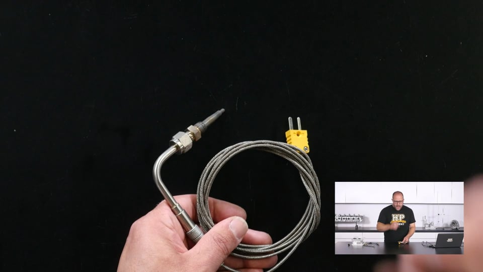
| 35:25 | So we talk about exhaust gas temperature sensors here, commonly they're referred to as exhaust gas thermocouples or EGT sensors, and the reason for that is that that's exactly what they are, they're a K type thermocouple. |
| 35:41 | So a K type thermocouple, if you're not sure what a thermocouple is, it's two dissimilar metals, in the case of a K type thermocouple, that's chromel and alumel. |
| 35:52 | And as those metals are exposed to a temperature differential across their length, they generate a voltage. |
| 36:00 | And those two materials generate a different voltage. |
| 36:03 | So what we do is at the actual measurement end here, we connect those two metals together so we know that that point, both those materials have the same voltage. |
| 36:13 | Then as there is a temperature differential across the length of those wires, if we measure the difference in voltage at the other end, we can actually calculate the difference in that temperature using some calibration curves again. |
| 36:28 | So this means that we need an uninterrupted line of those materials all the way from our sensor here to the device that is doing the measuring. |
| 36:40 | So what I mean there is the tip of your probe here might be exposed to the full heat of your exhaust gas stream, however at the other end where we've got those two dissimilar metals broken out, this might be easier to show on the overhead shot here. |
| 36:57 | I've got those two dissimilar metals broken out into their individual pins, this is where the actual measurement is going to be taken. |
| 37:03 | And what we're going to measure is the difference in temperature between this point and this point. |
| 37:09 | Now if this point is our ECU, our ECU was going to have an internal temperature measurement, which is used for safety and logging just to keep an eye on how hot the ECU us getting. |
| 37:19 | So it knows its absolute temperature, it knows the difference in temperature between these two points, so it can calculate the temperature of the exhaust gas at the tip here. |
| 37:31 | If instead of that we had our exhaust gas thermocouple coming to say a different connector where we then ran standard copper wires from that point back to our ECU, if that connector was located in the engine bay we would then only be measuring the difference between the tip here and that connector. |
| 37:51 | There could be another temperature differential between that connector and our ECU and we wouldn't be accounting for that so we wouldn't be able to get an absolute temperature measurement at the tip here. |
| 38:04 | The way we get around that is to make sure that we use chromel and alumel pins if we're having to pass the signal through a connector. |
| 38:13 | For your high level motorsport applications you're probably going to be using Souriau or Autosport connectors and they absolutely are available for those, but they are also available for Deutsch DTM connectors. |
| 38:25 | They're not particularly expensive and it definitely is worth going to the trouble of finding them. |
| 38:34 | They're not particularly tricky to source now, any aftermarket EFI wiring supplier's going to have them and it is definitely worth doing. |
| 38:43 | Now the voltage that these sensors output is actually very very small. |
| 38:49 | And that's the reason that I really like to run exhaust gas temperature signals like this through shielded cabling and you can get shielded K type thermocouple wiring and it's exactly the same as say running any other shielded cabling, you're going to wanna pass that shield through any connectors as well, to keep that signal integrity intact. |
| 39:12 | It's a really low level signal before it gets to the measurement element. |
| 39:16 | And you want to avoid getting any noise in that if possible. |
| 39:19 | It is a signal that can actually change quite abruptly. |
| 39:25 | However with a closed, what's known as a closed element sensor like this, you can see the actual thermocouple is completely encased in a steel sleeve here. |
| 39:34 | You're not going to see this change incredibly quickly. |
| 39:37 | You're not going to say pick up the individual pulses of the exhaust gas as they're coming out of the exhaust port, as there's a reasonably large thermal mass here to change the temperature of quite quickly. |
| 39:51 | There are open element exhaust gas thermocouples where that junction between the two materials is actually exposed to the exhaust gas flow. |
| 40:00 | Really really good for scientific measurement on the dyno or a little bit of quick datalogging but I haven't found them to be particularly reliable. |
| 40:07 | You're not going to get a full race meeting, most likely, out of those sensors. |
| 40:12 | But if you need to track down a problem, they can be a good idea. |
| 40:16 | They are available in the same form factor as your common EGT probe which uses what's known as a compression fitting to actually fit into the exhaust manifold and seal into it. |
| 40:27 | Now I talked before that these have a very low level voltage signal. |
| 40:31 | And for that reason a lot of ECUs aren't actually capable of interfacing to them directly so you do find a lot of devices out there on the market like the one we've got here which is made by Motorsport Electronics which is an exhaust gas thermocouple amplifier. |
| 40:46 | So we'll just pop over to that overhead shot again and you can see here, so this has a little bit of circuitry inside it and what it does is it converts that low level signal from our thermocouple into a standard voltage signal that our ECU can interpret. |
| 41:05 | So I haven't actually looked at the documentation for this, I don't know if they need to be powered by five volts or 12 volts, but I suspect it probably takes five volt sensor supply, sensor ground, and outputs a signal. |
| 41:19 | And our thermocouple gets inserted into the end there. |
| 41:23 | These are a really common thermocouple connector. |
| 41:26 | To be honest, I don't really like them that much as I haven't found them to be particularly reliable in a high vibration environment. |
| 41:32 | What you can do and you often see done to mitigate a lot of that is to actually cable tie around there in a criss cross fashion, and that keeps that together. |
| 41:40 | I have actually seen noise introduced from vibration and intermittent contact with the pins in here. |
| 41:46 | That being said though, one thing they do have going for them is that they're keyed so the different pins are different sizes so they only go together one way. |
| 41:54 | Now when we talked before about the measurement of a thermocouple is across the length of those materials, we'd need to be careful in this instance that we located this, so we need to be aware that in this instance we are actually only going to be measuring the difference between this connection point and our sensor. |
| 42:20 | And it's possible if there's any other temperature differential we might not get an exact absolute value for our exhaust gas temperature. |
| 42:25 | The absolute values for exhaust gas temperature aren't as useful as you'd think though. |
| 42:32 | What you're more looking for is for them to be nice and even over all the cylinders in your engine and that you're not seeing any that are spiking out of control. |
| 42:42 | Other things to be aware of as we mentioned I'm thinking to a particular example of an engine I've worked with which had very very short headers, is that no matter what we did, the signals we got from the exhaust gas thermocouples in that instance, anything below about 5000 RPM, the readings were basically garbage because there wasn't enough exhaust flow to prevent cooling gases getting back into the system and actually giving us really really bizarre readings. |
| 43:13 | So another thing to be aware of there. |
| 43:15 | And actually on that point, you see the same thing with oxygen sensors, and it was the same issue with this vehicle as well. |
| 43:21 | The oxygen sensor was located quite close to the exhaust exit point, so anything below I'd probably say about 3500 RPM in this instance, there was too much oxygen getting back into the exhaust when the valves were closed to give us a valid O2 sensor reading. |
| 43:40 | Yeah another really good one to be aware of. |
| 43:43 | Right last thing I'm gonna talk about now is CAN bus and why you should all love it. |
| 43:48 | But before I get into that, now's a really good time if there's any questions out there about any automotive sensor applications that you've got, pop them up in the chat and the guys will be firing those through and we'll get to those in just a moment. |
| 44:02 | So for CAN bus systems here, just gonna have a quick read of my notes to make sure I'm not gonna miss anything. |
| 44:10 | Right so when I say CAN bus systems, what I mean there is a sensor interface that's going to take the raw signal output from a sensor and convert it into data, the digital signals on our CAN bus network, and then is going to be fed back to the ECU. |
| 44:29 | You see them commonly called CAN bus expander modules or analog CAN modules. |
| 44:34 | They are really an absolutely fantastic way to go about getting some signals into your ECU. |
| 44:42 | At the very beginning of this webinar we talked about auxiliary ports and catering for those in your wiring harness. |
| 44:50 | Another thing we go into in the courses is actually catering for CAN bus expansion in the harness as well. |
| 44:56 | Absolutely totally critical and really easy to do is throw a couple of CAN access ports in your harness. |
| 45:02 | Put CAN high and CAN low, 12 volt power supply and a power ground in there, and just plug it up with an empty connector when you're not using it. |
| 45:11 | And then when you do need to get some extra data onto the CAN bus, you've got a really easy way of interfacing into that. |
| 45:17 | And you absolutely will not regret it. |
| 45:20 | Excuse me, sorry I did apologise and say there might be a coughing fit in the middle of the webinar, I'll just have a quick drink. |
| 45:31 | Things to be aware of when you're using CAN bus modules like this is that they're not to be used for any signals that are completely critical to the engine or that we're going to see changing very rapidly. |
| 45:44 | So primary in this is the engine speed and position signals. |
| 45:49 | That engine speed signal changes very very rapidly and because of the way ECUs work internally, the signal, when that signal comes into the ECU, and the ECU detects that it's made that zero crossing, it actually fires off what's known as an interruptor routine, it's like the ECU code and it's basically a really really quick way of the ECU detecting oh right OK that tooth has passed that sensor, I need to do something now. |
| 46:20 | If you put another processing stage in between that which would be our CAN bus module, it is going to introduce too much delay into the system and you're not going to be able to reliably keep track of your engine speed or position. |
| 46:33 | So engine position and speed are out for our CAN bus interface modules. |
| 46:38 | Other situations where you don't want to use them are for low level signals. |
| 46:43 | Low level signals that need to be read very very quickly, and the one that immediately springs to mind is knock. |
| 46:50 | So a knock sensor on an engine is nothing more than a microphone, and the ECU needs to be able to interpret the output which is the AC wave form from that microphone and to determine when sounds or the particular frequency and amplitude are occurring, and respond to them in an appropriate way. |
| 47:09 | Now you could have that being read by a CAN bus system and being fed into the ECU, but that extra processing stage in there is likely to actually cause you a few issues. |
| 47:19 | That being said, for elements such as, actually before we get into where we are gonna use them, there is one other situation where it would seem like it was a fantastic idea to use them but it doesn't work in practice and that's actually suspension position. |
| 47:35 | So this is suspension position potentiometers or shock travel potentiometers. |
| 47:39 | Once again really really fast changing signal, you do need to be reading those at a really really high rate, at least 1000 hertz, to get good reliable data out of them. |
| 47:51 | And you're not going to be reading CAN bus data values changing that quickly if there's that processing stage in between. |
| 48:00 | Now situations where it can be really good to read them are elements in the car where you're going to want to be measuring a lot of data but you're not expecting it to change too quickly. |
| 48:12 | And the situation where I installed a system for this recently where I was really really thankful it was CAN bus was actually tyre temperature. |
| 48:23 | So I bought some tyre temperature sensors from a company called Izze Racing, and what they are is basically an infrared camera, it reads an array of infrared spots, I think it was 16 wide by four high, uses the height of four to get an average and then it has 16 individual points across the tyre where you measure the temperature. |
| 48:46 | You're not actually expecting the tyre temperatures to be changing that quickly when we're talking about the speed that we can send data via a CAN bus system so this was a really really good implementation of a CAN bus system because I could wire these four sensors, build a sub harness for it, that had only one connection point into the main wiring harness of the vehicle, instead of needing to integrate all that wiring into the main harness to get those individual signals into the ECU. |
| 49:15 | There was a particular element that cropped up in that situation though is that those particular tyre sensors were powered via the five volt rail of the ECU. |
| 49:24 | Now each individual sensor in this situation drew 250 milliamps, so by the time you've got four of those in the car, that's actually a one amp draw, that's a really large draw on the five volt sensor supply of an ECU. |
| 49:39 | In this situation wasn't an issue because I got in touch with Izze Racing, and they supplied us with a separate 12 volt to five volt converter, at no charge I should say, so really good company to deal with and it allowed me to wire it into a standard CAN bus auxiliary port on that vehicle, which had 12 volt ground and the CAN high and the CAN low lines. |
| 50:03 | What else did I want to talk about there? Right most other additional sensors that you're going to want to be reading from chassis and engine parameters are going to be really good candidates for transmission via CAN bus. |
| 50:20 | The benefit you're going to get out of this is that that data is then going to be really easily available to any device that is on the CAN bus network of the vehicle. |
| 50:30 | So if you have a dash display logger and an ECU communicating via CAN bus, and you hook another sensor system into that CAN bus, both of those elements can now access that data without any issues. |
| 50:45 | What I would really, we're gonna get to the Q&A session really really shortly, just one final comment here. |
| 50:52 | If there's anyone out there that's into electronics and would like to develop a product, what I would really like to see is some sort of sensor, temperature sensors of around about our existing form factor that actually had some electronics inside them to output a CAN bus signal directly. |
| 51:10 | A company called STM makes a wee micro chip now that is suitable for the automotive environment, it has CAN bus functionality on it, you can get it in a tiny form factor, you could absolutely fit that in there, and if I had a bit more time, I'd jump all over it. |
| 51:25 | But if someone wants to get out there and develop that product, you'd have a very keen customer right here. |
| 51:30 | As if I could have all of those non critical parameters out there on a distributed CAN bus network in the vehicle, it would be the dream for setting that system up to handle all sorts of situations that you encounter down the line. |
| 51:48 | The most that you can decouple your wiring harness layout in the vehicle from getting a signal from one place to another, the better. |
| 51:59 | So by this I mean if you can avoid having to have a dedicated wire for getting a signal from a sensor to an ECU, then it's going to really open up the possibilities later on down the track for using that data somewhere else in the vehicle if it was just being put straight up onto a CAN bus for example. |
| 52:18 | So hopefully that's been a good discussion on sensors today. |
| 52:23 | Hopefully you've gotten a bit out of it and possibly some of the more obscure aspects of determining a sensor setup for your vehicle, some of the less common uses of some common sensors, and even some ideas about how you can get different data flowing around the car in a really good way. |
| 52:40 | So we're gonna jump over to the Q&A session now. |
| 52:47 | Right got a question here from Fallar, knock sensors, let's say he has an obsolete ECU like the Motec 100 series, he has a box that came with it which hears knock. |
| 52:57 | If he wants to send the signals to the ECU, is it possible? Yes it is, there are devices out there which are signal interface boxes which will take that knock signal analyse it, determine when knock is happening, and send that to a more common input in the ECU. |
| 53:13 | It's either going to be a digital input or an analog input. |
| 53:16 | If it's an analog input, the interface box is probably going to be able to output different intensities of knock, corresponding to different voltages. |
| 53:26 | As I've mentioned, it's not the ideal way to do it, if you can get the knock signal directly into the ECU, chances are things are going to be responded to much quicker, as you don't have that processing stage in between. |
| 53:41 | Knock detection in an ECU is, in my opinion, of less use than people commonly think it is. |
| 53:54 | It's absolutely fantastic as a protection strategy against accidental low octane fuel, but those are going to be quite serious knock events and you're definitely going to want to be responding to those. |
| 54:06 | A lot of people have this idea of inputting a knock input into an ECU that they're going to be able to immediately use that for tuning purposes. |
| 54:14 | It's really not the case, when you put a knock input from that knock sensor into the ECU, you need a device on which you can actually listen to the output of that knock sensor, determine yourself when knock is occurring, and calibrate the ECU to read those same knock events. |
| 54:31 | We've got some good, we've got a Youtube video that's got some audio of knock, the output of a plex knock sensor where you can actually hear knock occurring, so you can get an idea of what you're listening for, and actually just recently Jono and Alan undertook a project to get some much better audio recordings of knock happening so we were gonna hopefully generate a bit of content with that soon as it really is a big sticking point when you're tuning an engine, is determining how to listen for knock. |
| 55:01 | What are you actually listening for? There's a lot of descriptions of what it sounds like out there. |
| 55:08 | The most common that I can think of is when I think back to a particular Mitsubishi Starion I used to have that used to knock right when it was coming onto boost in that torque mid range of the engine which is pretty commonly where you expect to see it. |
| 55:23 | This was so bad that it sounded like someone was shaking a rattle can under the bonnet. |
| 55:31 | It really did sound like that ball bearing was rattling around in there. |
| 55:36 | That motor never actually died, it never actually destroyed any ring lands, I've got no idea why 'cause I thrashed it to death. |
| 55:42 | But when you're listening to it on knock phones it's more of an irregularity in the noise that you're hearing. |
| 55:49 | Hopefully the knock device is doing a good job of audio filtering out a lot of the other frequencies and you should be able to hear nice regular noises from inside the engine and if you hear an irregular sort of tapping or slapping noise, that is likely to be knock there. |
| 56:06 | Peter Parker has asked, he may have missed it, but the turbo speed sensor you mentioned, is an optical sensor or some type of pressure wave based sensor? Now optical sensing, actually that's interesting. |
| 56:19 | I suspect there would be a way to do it with optical sensing but I haven't seen it done. |
| 56:24 | The way I've seen it done is detecting eddy currents. |
| 56:26 | So these are currents formed in the sensor by the passing of that aluminium disc. |
| 56:32 | It's similar to a VR sensor but it's a bit of a different principle and always it is going to have that interface box to read those eddy currents and turn it into a signal that the ECU can interface with. |
| 56:44 | The actual implementation of it, if you head to the Garrett website, there's some good information there, it's not something you're really going to have to deal with when you're building an EFI wiring harness or tuning an EFI system as it is going to be catered for by that interface box there. |
| 57:00 | Edgemoney has asked, can he have an additional map in TPS on an LS ECU like an 0411 and how to you tune for it? Now I will admit here that tuning OEM ECUs is not really something that I have a lot of familiarity with. |
| 57:15 | Andre would definitely be the better person to ask about that. |
| 57:19 | In this instance I'm not gonna be able to answer that question for you but pop a post up on our forums and Andre will get in there, or one of our other knowledgeable forum members on particularly that platform will get in there and answer that for you. |
| 57:34 | Craig has asked, is there a way to convert a mechanical sensor to electronic? E.g. a speedometer. |
| 57:40 | So I think in this instance you'll be talking about an older style of speedometer which is cable driven and it's actually basically a magnet dragging around the needle working against a fixed spring. |
| 57:52 | Absolutely there'll be some way of converting that to an electronic signal. |
| 57:57 | I can imagine there's probably, I have definitely seen in line devices you can get that take a speedo signal, in one side, and output it on the other, so you can still send it through to your gauge cluster but they give you an electrical signal. |
| 58:12 | Most often these are going to be done with opto couplers. |
| 58:16 | So that's spinning a disc inside there which breaks a beam between an LED and the optical sensor. |
| 58:29 | So it breaks the light between them and then you can get your spinning frequency out of that, knowing how many teeth are on that disc. |
| 58:36 | There's probably as many ways to do it as you could think. |
| 58:41 | One thing I would say though is that it's really really common on vehicles, 'cause I know you're actually into the 70s series Supra, I'd be surprised if they didn't do it, on vehicles of that era, to actually have a cable driven speedo but there's still a little bit of electronics in there which outputs a speed signal back to the ECU. |
| 59:04 | I really shouldn't mention them because they give me a bad name, but once again I know the Starion does actually do this. |
| 59:09 | So I'd be very very surprised if the Supra wasn't doing that as well. |
| 59:16 | Right those are the questions we've got on today's webinar, so thanks heaps for joining us guys. |
| 59:22 | I hope it's been informative and didn't get too far off topic into the tech geekiness there which I am often a bit of a, yeah, inflict that upon you. |
| 59:35 | So thanks heaps for joining us, thanks heaps for those questions, and any other questions on the topic, make sure to fire to them up in the forum and we will get those answered for you. |
| 59:47 | Thanks heaps guys, I really hope to see you on the next one. |


