067 | Effect of AFR and Ignition Timing on EGT
Summary
Exhaust gas temperature or EGT is one of those parameters that is often mentioned but seldom discussed. In particular the specific EGT will be influenced by both the air fuel ratio and the ignition advance. In this webinar we will see exactly how these tuning parameters effect the measured exhaust gas temperature.
This webinar will be performed on our engine dyno using a Toyota 1ZZFE engine fitted with a Link G4+ Fury ECU.
| 00:00 | Thanks for joining us for this webinar. |
| 00:02 | I'm Andre from the High Performance Academy and in this webinar we're going to be analysing the effect of various tuning parameters, specifically our air fuel ratio and our ignition timing on the exhaust gas temperature of the engine. |
| 00:20 | Now, we're going to be doing this today using our Toyota 1ZZ-FE engine fitted to our Mainline engine dyno. |
| 00:28 | Of course the results that we're going to see are going to be applicable to just about any engine. |
| 00:35 | Now, before we get started, we want to talk a little bit about these exhaust gas temperature sensors. |
| 00:42 | Now, it's a question that we've received numerous times through both our public and our members only webinars. |
| 00:51 | Particularly, the question normally goes something along the lines of "What exhaust gas temperature is safe for my XYZ engine?". |
| 01:00 | And the problem with that, which I've reiterated in these other webinars and I'll cover again now, is a lot of the specific reading from our exhaust gas temperature sensor will depend on both the sensor and the location of that sensor in the exhaust system. |
| 01:19 | So, before we actually get into the webinar, we're going to just talk a little bit about these sensors, where you should place them, and just as importantly, how we can actually get the data from these sensors. |
| 01:31 | So, I've got an exhaust gas temperature sensor here, which hopefully you'll be able to see reasonably clearly on your screen. |
| 01:39 | This is a relatively typical sort of exhaust gas temperature sensor. |
| 01:45 | It's already seen some use in our Toyota 86 pre-turbocharger. |
| 01:51 | Generally, when we're looking at purchasing an exhaust gas temperature sensor, there's two different models of sensor, or generic groups I guess you could call that the sensors fall into, and I refer to them as exposed or encased tip. |
| 02:10 | It refers to the construction of the sensing element right at the very end of your exhaust gas temperature sensor. |
| 02:18 | You can see at the moment, there's a, hopefully you can see, there's a sort of an encased tip here that protects the actual sensing element. |
| 02:28 | So, that is an enclosed or encased tip sensor that I've got there as an example. |
| 02:33 | Now, the way the thermocouple works is at the tip of the sensor, we have a junction between two dissimilar materials, two dissimilar metals. |
| 02:44 | And it's this junction that creates very, very small voltages, which vary in relation to the temperature that that junction is exposed to, is surrounded with. |
| 02:58 | Now, the problem with the exposed tip, where we have that junction physically out there in the exhaust gas stream is it is quite fragile and it can be damaged. |
| 03:09 | So, the encased tip sensor will give you longer sensor life. |
| 03:14 | It's a much more hardy type of sensor. |
| 03:17 | But the downside of it is in my own experience that they tend, particularly under transient conditions, to read a little bit cooler than an exposed tip. |
| 03:28 | They also tend to read a little bit slower, respond a little bit slower. |
| 03:33 | It takes them longer to actually change. |
| 03:36 | And once we look at the demonstration on the dyno today, you're going to see that the exhaust gas temperature sensors do respond really quite slowly. |
| 03:46 | Okay, so, that's one aspect of the reading you're going to get out of your sensor, is the type of sensor you're using. |
| 03:55 | Actually, the other aspect I should mention is there's two different diameters that are typically available in these sensors. |
| 04:03 | This is a larger 3/16th diameter sensor. |
| 04:07 | The other sensor, sorry, this is a quarter inch diameter sensor, which is a little bit more hardy. |
| 04:15 | These are the sort of sensors you're likely to see in professional motorsport drag racing use. |
| 04:20 | There is a thinner, I think it's a 3/16th sensor, available as well. |
| 04:27 | Those are the two typical sizes. |
| 04:29 | I'm hoping I've got those right from memory. |
| 04:30 | The smaller sensor which I used to use on my own drag car, again, a little bit more fragile and I found that I was replacing sensors quite frequently. |
| 04:40 | So definitely, if you are in the market for sensors, I would look at the larger diameter sensor. |
| 04:45 | It's going to last longer, be a little bit more robust. |
| 04:49 | So, the other aspect to your sensor reading is going to be whereabouts in the exhaust system you've got this located. |
| 04:56 | So, in our example with our 1ZZ-FE, we've got four individual cylinder exhaust gas temperature sensors and they're all mounted about 50 millimeters from the exhaust header flange. |
| 05:09 | So, they're directly in the exhaust flow, straight out of the exhaust ports. |
| 05:15 | The other common scenario would be where we only have a single exhaust gas temperature sensor fitted to the engine and often this will be fitted in the collector pre-turbocharger. |
| 05:27 | Now, while it is possible and also beneficial to fit exhaust gas temperature sensors to naturally aspirated engine, we do find more often they are fitted to turbocharged engines, particularly if we're only using a single sensor in the collector. |
| 05:44 | That sensor in itself is not particularly useful for helping us with aspects such as individual cylinder fuel trimming, et cetera. |
| 05:54 | We're only really seeing a collector exhaust gas temperature, which is relevant still, but not overly useful in the big scheme of things. |
| 06:04 | Now, if we've got a sensor mounted in the collector, that may be some 500, 600, 800 millimeters from the exhaust port, obviously depending on your exhaust manifold design. |
| 06:17 | And the exhaust gas temperature reading you will get in the collector is going to understandably be lower than what you'll get at the exhaust port. |
| 06:28 | So, all of these factors need to be taken into account and understood, and this really adds up to why there isn't one specific ceiling value that you can apply to exhaust gas temperature in every application. |
| 06:42 | There are quite a lot of discrepancies between different sensors in different locations. |
| 06:49 | Lastly, I wanna talk about how the sensor is terminated. |
| 06:53 | So, with the test sensor, the example sensor that I've got here, you can see that it comes with a length of wire and it is terminated in what is a relatively typical thermocouple connector. |
| 07:10 | So, this would go straight into your thermocouple module or whatever you're using to read the exhaust gas temperatures. |
| 07:21 | Now again, backing up to how I was talking about how the EGT sensor works. |
| 07:27 | It uses the junction between two dissimilar materials and it's the temperature at that junction that counts. |
| 07:36 | The only problem is we also end up with another junction at the opposite end of the sensor. |
| 07:42 | And what we're actually reading with our exhaust gas temperature sensor is the difference in temperature between the temperature at the tip of the sensor where one of our junctions is and the temperature at the connector, which is where our other junction is. |
| 08:00 | This is often known as a cold junction. |
| 08:04 | So normally, that works out just fine. |
| 08:07 | Often we'll have the cold junction mounted inside the cabin and when we're looking at exhaust gas temperatures of perhaps seven, eight, 900 degrees centigrade, perhaps an ambient cabin temperature of 20 to 35 degrees centigrade isn't really a big bearing on our reading. |
| 08:26 | It is however also quite common to see the exhaust gas temperature sensors terminated in the engine bay. |
| 08:34 | And in that case we can get quite a difference in our cold junction temperature. |
| 08:39 | It's probably not uncommon to see the engine bay temperature sitting anywhere from 40 to maybe 70 or 80 degrees centigrade depending exactly where those sensors are located. |
| 08:50 | And obviously that then can start having a significant influence on your outright reading. |
| 08:56 | Some thermocouple amplifiers include the option to do what's called a cold junction compensation. |
| 09:07 | And what you do with that, an example of that system would be MoTeC's E888 and E816 expansion units, which have on board thermocouple amplifiers. |
| 09:18 | In that case what you can do is run a temperature sensor to the vicinity of your cold junction, so wherever you've got your thermocouple plugged in or terminated, be it in the cabin or in the engine bay, and that cold junction temperature sensor will then correct your actual exhaust gas temperature reading. |
| 09:39 | It's a little bit long winded, I apologise for going into this in so much detail, but I do feel this is an important aspect that so many people either don't understand or alternatively overlook. |
| 09:50 | The last part to do with terminating that thermocouple sensor is quite often we'll find that the length of these sensors isn't ideal or we want to perhaps neaten the wiring, so it's not uncommon for many people to just lop off the connector as it comes and terminate it in something more readily available, perhaps a Deutsch DTM connector or something like that. |
| 10:17 | Remember that wherever you terminate that sensor and run it into conventional wire, that is where your cold junction will become, so that's going to affect your actual reading. |
| 10:30 | If you want to extend your thermocouple, you can buy special thermocouple wire. |
| 10:36 | This maintains the two dissimilar materials so you can extend it without affecting or without creating a cold junction, so that's another aspect. |
| 10:45 | At some point obviously we do have to have a cold junction somewhere in the system though. |
| 10:50 | In my experience, the systems I have used, more often than not the cold junction temperature compensation is just simply completely ignored. |
| 10:59 | As long as you understand the implications of that, it doesn't really matter. |
| 11:04 | Ok, I think we've probably covered the actual sensors now. |
| 11:09 | One other thing I will mention, particularly if you're going to be mounting individual cylinder EGT sensors, in order to get useful data out of them, it's really critical that they are all mounted equal distance from the header flange, and that they are protruding in equal distance into the exhaust manifold. |
| 11:31 | So, the temperature gradient inside the exhaust manifold will vary with location and typically what we're going to do is have this probe extending to as close to the centre of the exhaust runner as possible. |
| 11:47 | Again, that's not so critical as the aspect that all four or six or eight, however many sensors you've got, are located absolutely identical. |
| 11:58 | If they're not, it's going to affect the cylinder to cylinder exhaust gas temperature reading and that's going to make your reading somewhat useless. |
| 12:07 | Ok, now the other thing I'm going to talk about with this is how we actually get a reading out of these sensors, how we get that data into our ECU, our dash or data logger. |
| 12:18 | These exhaust gas temperature sensors create a voltage that's incredibly small. |
| 12:24 | So, in order to do something useful with that data, we need to run them into what's generically known as a thermocouple amplifier. |
| 12:33 | So, that's simply, as its name implies, multiplies or amplifies the voltage coming out of these sensors and generally scales it into something that can be read by your ECU or data logger. |
| 12:46 | Common type would be a sensor amplifier, which outputs a zero to five volt analogue signal which can be read into your ECU. |
| 12:57 | The one that we're actually using on our test engine is Haltech's TCA4 which is a four channel thermocouple amplifier. |
| 13:05 | That has the ability to both communicate via CAN as well as analogue voltage. |
| 13:12 | So, it's able to be used with a wide range of products including obviously all Haltech's ECUs simply as a plug and play product, or other devices by doing a little bit more wiring. |
| 13:25 | Ok, let's start actually looking at what's going on in the ECU now. |
| 13:30 | I've probably talked enough. |
| 13:32 | What we've got on our PC Link software here is we have a box that I've just added in, which has the exhaust gas temperature from all four cylinders. |
| 13:45 | Now, for this particular webinar we're not actually going to be looking at matching the exhaust gas temperature from each cylinder. |
| 13:53 | So, what I'll do is I will just drag, just modify the properties of this box here and I'm going to remove three channels just because otherwise it does get a little bit confusing and it can be a little bit hard to exactly tell what's going on. |
| 14:14 | So, I'm going to be presenting this demonstration using the exhaust gas temperature in degrees centigrade rather than Fahrenheit, so I do apologise for those of you who are used to working in Fahrenheit. |
| 14:25 | Of course, feel free to convert that in your leisure if you need to use Fahrenheit values. |
| 14:33 | Ok, so the first demonstration we're going to look at is the effect of our ignition timing on the exhaust gas temperature. |
| 14:43 | So what I'm going to do now, we'll just get our fan running on our dyno and I'm just going to bring the engine up to 3000 RPM and we'll just apply a little bit of load here. |
| 15:02 | So, I've got the engine running at minus 55 kPa. |
| 15:06 | Now, the first thing you want to notice is the engine's now running in steady state. |
| 15:10 | You can see that the exhaust gas temperature is still continuing to increase, and this is what I was talking about with the delay, the speed in which the exhaust gas temperature tends to react. |
| 15:24 | It is a very, very slow sensor, particularly when we compare it to our lambda, which you can see down below. |
| 15:32 | So we still haven't even quite reached sort of an equilibrium. |
| 15:37 | We're still increasing. |
| 15:38 | We're sitting at about 640 degrees centigrade now. |
| 15:41 | What I'm going to do is swap over to our ignition table and you can see I've highlighted all of the cells around the actual site that the engine's running in at the moment. |
| 15:57 | So, we seem to have reached probably roughly an equilibrium. |
| 16:00 | We're sitting at around about 657, 656 degrees centigrade. |
| 16:06 | What I'll do now, just for a quick demonstration, we're going to look at this in a little bit more detail. |
| 16:11 | Let's take 10 degrees out of the ignition advance. |
| 16:14 | So, we'll enter a value of 20. |
| 16:19 | Try and enter a value of 20. |
| 16:24 | It's going to be one of those days where everything just doesn't quite work right. |
| 16:33 | Ok, now we're going to enter a value of 20. |
| 16:35 | So, you can see we're sitting at the moment 667, 666 degrees. |
| 16:41 | I've just retarded the timing. |
| 16:43 | And you can see that taking that 10 degrees out, we've picked up at the moment around about 15, 20 degrees centigrade in our exhaust gas temperature. |
| 16:55 | And it's actually still, we're sitting at 20 degrees now, we're still continuing to climb. |
| 16:59 | So, when we retard the ignition timing as I did there with that demonstration, what's happening is the ignition event is happening later or beginning later in the engine cycle, which means that there is more exhaust gas temperature provided. |
| 17:16 | So, now we've gone up from 667, we're almost up 30 degrees in exhaust gas temperature now. |
| 17:25 | Ok, so we were at 30 degrees. |
| 17:27 | So, what I'll do is advance the timing up to 40 degrees. |
| 17:31 | Remember, when we were at 30 degrees, we had about 667 degrees centigrade. |
| 17:40 | And you can see that now we're up to 40 degrees. |
| 17:42 | Our exhaust gas temperature's dropped from that peak we had at 20 degrees. |
| 17:48 | We're dropping down. |
| 17:51 | Again you can see how incredibly slowly the actual sensor does respond. |
| 17:57 | But you can see we are still dropping down. |
| 17:59 | If I allow this to carry on, what we're going to see is that with the ignition advanced 20 degrees from where we started this test, we're actually gonna see a slight drop off in our exhaust gas temperature. |
| 18:14 | Now, the point of this demonstration is that there's so many parameters that will affect our exhaust gas temperature and again this comes into bearing like when I get asked the question, what is a safe maximum exhaust gas temperature? Obviously, the exhaust gas temperature is influenced by our combustion temperature. |
| 18:36 | And really that's the key aspect to the reliability or life expectancy of our engine, the actual combustion temperature. |
| 18:45 | So, all things being equal, when our combustion temperature increases, so does our exhaust gas temperature. |
| 18:52 | But it's also not strictly possible to draw a straight line correlation between our exhaust gas temperature and our combustion temperature. |
| 19:02 | There are other aspects at work in there that can affect the actual exhaust gas temperature reading. |
| 19:11 | Now, what I'm going to do is we'll log some data here. |
| 19:16 | I'm going to start by retarding the timing back to 10 degrees and again I'm just going to have to do this manually. |
| 19:24 | And we'll do a torque optimisation test to see the way the exhaust gas temperature varies as we move our ignition timing from 10 degrees up to about 45. |
| 19:41 | So, what I'm going to do is I'll log this onto our PC Link software, while I do this torque optimisation test. |
| 19:50 | And afterwards we'll be able to see the effect of the ignition timing on our EGT on number one cylinder. |
| 19:59 | So, what I'm going to do, I'll click begin there and now what I'm going to do is just advance the timing at a degree every second. |
| 20:09 | And remember we started at 10 degrees. |
| 20:14 | Just going to advance the timing slowly but surely all the way through to 45 degrees. |
| 20:21 | And what you're going to be able to see on the torque optimisation test, the little red line that's being drawn at the moment is plotting how the engine torque measured by the dyno is changing with ignition timing. |
| 20:37 | So, this is the typical way that we do our MBT tuning. |
| 20:40 | So, this is how we optimise our actual ignition angle in particular sites in the ECU anyway. |
| 20:48 | And we can visualise very easily what's going on with the engine torque versus ignition timing. |
| 20:59 | Ok, we're just about getting up to our 45 degrees now. |
| 21:05 | And you can see that the dyno has plotted our torque. |
| 21:12 | You can see our red line here which is our engine torque. |
| 21:15 | What I'll do is I'll just stop this test now. |
| 21:19 | And I'll also stop our PC Link logging. |
| 21:23 | So, what this has shown us is that for that particular site in the ECU's ignition table which was 40 kPa and 3000 RPM, our optimal ignition timing, our MBT timing which stands for maximum brake torque timing or minimum timing for best torque, is 37.2 degrees which resulted in 38 Newton metres. |
| 21:46 | Now, let's have a look at our logging. |
| 21:48 | And we'll be able to see in our logging the correlation between our ignition timing, which is shown here in blue. |
| 22:00 | You can see that we started at 10 degrees and I've advanced the timing all the way through to 45. |
| 22:07 | At the same time we have our cylinder one exhaust gas temperature which you can see at the start of this test was sitting at around about 745 degrees. |
| 22:19 | At the end of the test at 45 degrees of ignition advance, we went from 745 down to 673 degrees. |
| 22:30 | So, we've dropped around about 70 degrees out of our exhaust gas temperature as we advanced the timing. |
| 22:38 | So, you can see there's a very significant effect on our exhaust gas temperature. |
| 22:44 | And where we wanted to be, around about 37 degrees here, you can see that's this point here, and at that point we had in our exhaust gas temperature reading of 686 degrees. |
| 22:59 | Now, the next test we're going to do is we're going to look at how the exhaust gas temperature is influenced by our air fuel ratio. |
| 23:10 | So, the effect there is, remember what we're trying to do when we're choosing an air fuel ratio for our engine, is we're trying to match the fuel delivery to suit the amount of air entering the engine. |
| 23:27 | And we've talked in our last two webinars, which are in the archives already, if you want to investigate those further, about choosing the correct air fuel ratio and why we choose a certain air fuel ratio for both a naturally aspirated engine or a turbocharged engine. |
| 23:46 | The essence there is, particularly under wide open throttle, we're choosing a richer air fuel ratio, and we're choosing that for two reasons. |
| 23:56 | Firstly, what we want to do under wide open throttle conditions is make sure that we're supplying enough fuel to properly mix with all of the available oxygen entering the cylinder, and if we do that, that's going to ensure that we make maximum power. |
| 24:13 | The other aspect of this though is we're also going to be adding some additional fuel, targeting a richer air fuel ratio, and the reason for this is we're using that additional fuel to help cool the combustion temperature and control that combustion temperature, so we don't run into problems with engine reliability, perhaps melting parts inside the engine, perhaps having the piston expand too much due to heat and nip up in the bore, and also the other very serious issue is as the combustion temperature increases, particularly if we're running on pump fuel, we become much more prone to suffering from knock or detonation. |
| 24:58 | We really want to make sure at all times that we're staying away from knock or detonation. |
| 25:04 | So, what we're going to do now is we're going to do a quick demonstration at wide open throttle, and we're going to again do this run at 3000 RPM, and what I'm going to do is just retard the timing in these zones a little bit further below what I'd normally operate at, and the reason I'm doing this is just during this test I want to ensure that detonation isn't going to occur. |
| 25:32 | Remember, as I lean out the air fuel ratio, we're going to be creating a lot more combustion temperature, and this is going to make the engine much more prone to suffering from knock or detonation. |
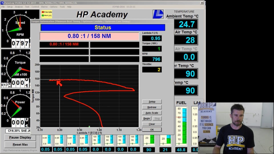
| 25:46 | Now, while I do this test, we're going to again log our exhaust gas temperature and our air fuel ratio, and during this demonstration we're going to do another torque optimisation test, just again so you can see exactly what's going on, how the air fuel ratio affects our engine torque. |
| 26:08 | So for this particular test what we're going to do is measure our lambda value. |
| 26:14 | I'm going to start with a very rich air fuel ratio or lambda value, I'm going to increase the fuelling until we have an air fuel ratio around about 0.75 lambda, and then we're going to lean it out progressively during the test all the way to 1.1, 1.15 lambda, and we'll be able to see the effect of that on both our exhaust gas temperature as well as our engine torque. |
| 26:44 | OK so what I'm going to do now is we'll just allow the exhaust gas temperature to reach some kind of equilibrium here, and again you can just see how slowly the exhaust gas temperature does respond. |
| 26:58 | OK so we're probably getting reasonably close to some semblance of equilibrium. |
| 27:05 | We will stop our test, clear everything we've got now, and I'm going to click start. |
| 27:14 | So what I'm going to do now is we're just going to progressively lean out the air fuel ratio and we're going to get it all the way from our starting point of 0.75 all the way through to 1.15, and the result of this will have a plot on our dyno of the lambda versus torque, so we'll be able to actually see how the torque is affected by our air fuel ratio, and at the same time after the test is complete, we're going to be able to have a look at our PC Link logging and see exactly how the exhaust gas temperature was affected as we leaned out that air fuel ratio as well. |
| 28:04 | So, we're getting up to 0.96, 0.97 lambda, and you can see our exhaust gas temperature now, we're getting up towards 720 degrees centigrade. |
| 28:16 | At the same time with such a lean lambda value at wide open throttle, you can also see that our torque is starting to plummet compared to where we saw our peak value achieved. |
| 28:30 | Ok, so we're at 0.17, 0.18, I'm going to stop that test now and we'll bring our engine back to idle and just talk about those results. |
| 28:42 | I'll just stop our PC Link logging. |
| 28:44 | Obviously, I wouldn't suggest necessarily that you go and run that particular test on any engine on a dyno running that lean at wide open throttle. |
| 28:55 | Obviously, can have some fairly serious downsides. |
| 28:58 | You'll notice that there's two things working in our favour here. |
| 29:01 | First of all, this engine that we're using, our Toyota 1ZZ-FE, is a naturally aspirated engine that frankly doesn't make a huge amount of power. |
| 29:10 | So, its ultimate combustion temperature is always going to be a little bit lower than perhaps a more serious engine or something with a turbocharger or supercharger. |
| 29:19 | So, that works in our favour for engine reliability. |
| 29:21 | Also remember before this test began, I also retarded the ignition timing. |
| 29:27 | So, I gave myself a wider margin from knock just to safeguard our engine. |
| 29:33 | Now, you can see if we look at our dyno plot here, we actually saw, strangely enough, that our peak torque was supposedly delivered here at 0.80 lambda. |
| 29:46 | That's pretty uncommon for a naturally aspirated engine and I'd put that down to probably more the amount the torque was being varied in general. |
| 29:57 | You can see from our starting point, 0.75, all the way through to probably around about 0.90, our torque is almost essentially flat. |
| 30:07 | What you can see though is as we continue to lean the air fuel ratio out, we drop from a peak of 158 newton metres down to around about 105, 110 newton metres. |
| 30:20 | So, a significant drop off as we go leaner. |
| 30:23 | Let's have a look now at our logging and I'll just zoom in on the area that we're interested in. |
| 30:30 | And we can see first of all here we have, I'll just get rid of our ignition timing because it's not something we were varying in that test. |
| 30:40 | We're in light blue here, our measured lambda. |
| 30:43 | The darker blue line is our target lambda, which in this case isn't that relevant to our test. |
| 30:49 | So, you can see that we started at 0.75 and we leaned the air fuel ratio out all the way to 0.17. |
| 30:56 | And our cylinder one exhaust gas temperature, at the start of our test we reached a relative equilibrium around about 620 degrees centigrade. |
| 31:07 | And you can see that we actually reach a peak exhaust gas temperature of 721 at around about 1.06 lambda. |
| 31:18 | When we actually continue to lean the air fuel ratio out, you can see that our exhaust gas temperature actually drops again. |
| 31:29 | Now, this is something that a lot of people probably on the face of it don't expect or don't think that they're going to see and don't necessarily understand why. |
| 31:41 | Now, remember there's two aspects going on here. |
| 31:44 | As we lean the air fuel ratio out, to a degree we're removing some of that additional fuel that we're using for cooling the combustion charge. |
| 31:53 | However, remember with our torque plot what we saw is as we lean out the air fuel ratio, we do also start to see the engine torque start to be reduced. |
| 32:04 | Now remember, one of the reasons we were adding that additional fuel in the first place was to make sure that we were combusting all of the available fuel and air inside the cylinder, or more particularly, more correctly, all of the available oxygen. |
| 32:21 | We don't really have an influence over that, that's down to the engine's design. |
| 32:26 | Our job as a tuner is to mix that air with fuel so we make maximum power. |
| 32:32 | So, as we start leaning out the air fuel ratio, suddenly we don't have that situation. |
| 32:37 | There's air, there's oxygen in that cylinder that's quite likely not being combusted, it's not being mixed with fuel so we're not seeing maximum power. |
| 32:46 | And that's why we started to see the torque drop off. |
| 32:49 | Now, of course when we're not combusting as much air and fuel in the cylinder, the result is the combustion temperature and hence the exhaust gas temperature actually starts to drop. |
| 33:00 | And that's what we're seeing here in this particular area where we lean from 1.06 to 1.18. |
| 33:11 | Now, particularly in aviation, the engines quite frequently, particularly with light aircraft, private aircraft, the engine technology is relatively crude by our standards with modern EFI. |
| 33:26 | However, a sensor that's quite commonly fitted is an exhaust gas temperature sensor and that's often used by the pilots to determine when the engine is making peak power. |
| 33:36 | And they affect the air fuel ratio as they're flying the plane and a general guideline is that the engine will be making peak power somewhere around about that point where we see peak exhaust gas temperature. |
| 33:49 | My own testing on the dyno, it doesn't tend to completely sort of follow along that pattern ,but it is a good guideline and remember the reason for that is that when we're combusting the maximum amount of fuel and air, we're going to see peak cylinder temperature, combustion temperature, peak exhaust gas temperature and also that's going to be an indicator of our power. |
| 34:17 | Now, one thing just to keep in mind and again this comes down to the delay, the latency or lag that we see in our exhaust gas temperature readings. |
| 34:27 | It's important that if we wanted to look at the exhaust gas temperature at a certain operating point in the engine's operating envelope, it's going to take seconds, like perhaps 30 or 45 seconds for the exhaust gas temperature reading to completely stabilise and reach an equilibrium point. |
| 34:51 | So, even the graph, the log data that we have here on our PC Link software of exhaust gas temperature versus lambda, even with how slowly I was leaning out that air fuel ratio and allowing the exhaust gas temperature to respond, there's a very good chance that there's still a lag in that system and if we left the engine operating at a particular point, let's say 1.01 lambda, which at the moment we're sitting at 717 degrees centigrade, if I simply left the engine operating there at that lambda, that RPM, that throttle opening, we would probably see the exhaust gas temperature continue to climb before it actually reaches an equilibrium. |
| 35:39 | So, the point there is it's a very very slow responding sensor and you need to understand that if you're going to base any of your tuning decisions on the sensor. |
| 35:50 | Ok, we're going to move into some questions now so if you do have any questions, please feel free to ask them now. |
| 35:59 | And if I can get this laptop to work, I'll be able to see if we do have any questions. |
| 36:07 | This particular webinar for whatever reason has been a complete disaster from a technical standpoint so I do apologise and thanks for bearing with us guys. |
| 36:18 | Ok, MCR has asked, "Can the Haltech TCA4 communicate by CAN on any other ECUs?". |
| 36:28 | Yes it can, no pun intended there. |
| 36:32 | And that's exactly how we're actually getting the data into our PC Link software. |
| 36:36 | This isn't a communications protocol that Haltech at the moment are making publicly known. |
| 36:46 | Some ECU manufacturers with their components that communicate by a CAN, that data is freely available so anyone can use it on any particular system. |
| 36:55 | Others tend to keep that information a little bit more private. |
| 36:58 | However, it's a relatively simple system. |
| 37:01 | Using a CAN decoder we can see what address that data's being transmitted on and I decoded it with relative ease to display on our PC Link software. |
| 37:12 | So, it does probably require a little bit of intelligence on the part of the tuner to get that up and running though. |
| 37:21 | Deucey's asked, "On a turbo car is it beneficial to retard the timing just before boost to increase exhaust gas temperature and spool?". |
| 37:29 | Ok, this is a really good question that we again get quite frequently. |
| 37:33 | And there's two aspects to promoting fast spool up on a turbocharged car. |
| 37:39 | One is the exhaust mass flow and the other is the temperature of that exhaust gas. |
| 37:45 | Now, generally my own testing, my own experimentation has shown that we're actually going to find that while retarding the timing will obviously build exhaust gas temperature as we've just seen, with a turbocharged car generally we're going to get a better result in terms of engine performance and spool if we tune the ignition timing during that spool up phase of the operation to MBT timing. |
| 38:16 | So, we're really tuning for optimal ignition timing to create maximum engine torque, even if that does negatively affect our exhaust gas temperature, so it reduces our exhaust gas temperature, that in my experience does give a better result. |
| 38:31 | Conversely, if we're talking about an anti lag or two step launch control setup, then in that case retarding the timing is what we want to do. |
| 38:40 | That has two effects of course, one is we do increase the exhaust gas temperature, but much more importantly we're resulting in the combustion actually occurring in the exhaust manifold itself. |
| 38:54 | Rip Veen has asked, "I joined a little bit late to the webinar, what thickness thermocouples are we using?". |
| 39:03 | So again, I've got it right here in front of me, this is an example of what we've got in the engine and these are the quarter inch diameter, so the thicker of the two that are available and just to reiterate, the smaller diameter sensor that's available, 3/16th I think from memory, is generally in my own experience not quite as reliable long term. |
| 39:26 | Rip Veen's also asked "When leaning further from 1.06 to 1.1, you notice the drop in both temperature and torque, could this possibly be due to a lack of mixture preparation?". |
| 39:41 | So, what you're talking about there is do we have a mixture that wasn't, a homogenous mixture of fuel and air? Well, ultimately when we see that torque drop off, it means that we're not getting, we're not fully combusting all of the available oxygen, so essentially yes we don't have a homogenous air fuel mixture. |
| 40:02 | At some point if we continue to go leaner, we're also going to find that the engine will probably, almost certainly start lean misfiring and that's where the core of air and fuel mixture around the spark plug is too lean to be reliably ignited. |
| 40:19 | In fact, it's probably a surprise that we were able to get all the way through to about 1.17, 1.18 lambda on this engine without that occurring. |
| 40:31 | Scraggy's has asked, "Worth noting about cold junction compensation via an inline controller, some EGT amplifiers such as the AEM have onboard cold junction compensation so need to thermo couple connectors and wire all the way to the amplifier box.". |
| 40:48 | That is a good point that I'll just add to there. |
| 40:51 | So, it depends what sort of thermocouple amplifier box you're using. |
| 40:57 | So, some such as the Haltech have an onboard connector that mates directly to our conventional thermocouple connector. |
| 41:07 | Others, such as the MoTeC E888 or E816, we need to actually wire the terminals directly into the connector, it's an AMP plastic connector on the E888 and an Autosport connector on the E816. |
| 41:27 | So, if you are wiring up to a thermocouple amplifier that uses the conventional thermocouple connector, then if you are extending your wiring, you will need to do so using proper thermocouple wire, otherwise you're going to get a problem in accuracies with your reading. |
| 41:47 | MCR has asked "What's a CAN decoder, is that software or hardware?". |
| 41:51 | Well, it's actually both. |
| 41:53 | In fact I'd probably recommend if you search in our webinar archive, we did an introduction to CAN webinar, which will probably have a lot of information there that'll be valid or important to you. |
| 42:08 | So, our Mainline chassis and engine dynos both have a built in CAN decoder and it's a piece of software inside the Mainline dyno as well as a CAN to USB adapter. |
| 42:22 | And looking at that software, basically what it will do is display anything that's being communicated on the CAN bus to that CAN to USB adapter. |
| 42:33 | You can also buy standalone CAN to USB adapters and various software packages to do this on your laptop as well. |
| 42:42 | Some of them are also quite cheap, in the order of just 100 or 200 US dollars. |
| 42:48 | So if you're interested in getting into CAN, that's an essential element. |
| 42:54 | Slidewise has asked "Would you suggest the larger EGT sensor when using an anti lag system?". |
| 43:01 | Absolutely, if you're using anti lag in particular, it is very very hard on all of the components in the exhaust system. |
| 43:10 | Again, I'll just separate this, because people get confused. |
| 43:15 | When I talk about anti lag, really what I'm talking about is a rally style of anti lag which is operational off throttle, when the driver is off throttle. |
| 43:25 | I refer to the drag race style of launch control or two step, or as a two step system as opposed to anti lag so I just want to be clear there. |
| 43:36 | So, an anti lag system, particularly on a rally stage, creates a lot of heat in the exhaust system for an extended period of time and this can be very very damaging to anything in the system, particularly the exhaust gas temperature sensor. |
| 43:50 | In that case an encased tip and the larger quarter inch diameter sensor would be almost an essential element if you want to get any reliability from those sensors at all. |
| 44:02 | MCR's asked "How long does an exposed sensor last and does it have a better response?". |
| 44:09 | Yeah so, I've run in my own drag car, not knowing any better at the time, I started with the small diameter sensors, which I've already mentioned and I also started using exposed tip. |
| 44:22 | And we do see, I had experience with my drag car on both the exposed and encased tip sensors and this is why I know from first hand experience, we do see a difference in that temperature reading. |
| 44:37 | So, the exposed tip sensors, I was seeing life expectancy of no more than about four or five drag meetings, so relatively short, we couldn't get through a full season of drag racing with that car without replacing one or two sensors. |
| 44:56 | The encased tip on the other hand, while they did read lower, and from memory on my particular car, they read as much as 80 to 100 degrees centigrade lower so it is quite significant. |
| 45:11 | So, those sensors would tend to last more than a full season of drag racing without any problem. |
| 45:20 | Rip Veen's said "OEMs tend to use very thin thermocouples during calibration, not at all suited to long term but all geared towards EGT response.". |
| 45:29 | What we also find with the OEMs is that they will actually in a lot of cases model inside their software exhaust gas temperature. |
| 45:39 | So, they often will, quite frequently will not have any exhaust gas temperature sensor fitted to the vehicle at all. |
| 45:47 | Obviously, exhaust gas temperature's critical to the operation of the catalytic converter on an OE car and it's really one of the key aspects of getting their engines up to emission standard. |
| 45:59 | So, it's very important for them that they know exactly what's happening. |
| 46:02 | So, during their calibration and testing on engine dynos as well as out on the road, well before these engines ever make it to production, they will know for, they'll be able to create and generate models for a certain operating condition, what the exhaust gas temperature is going to be. |
| 46:21 | In the aftermarket we're using these sensors for very different purposes. |
| 46:24 | So, not strictly comparable in my opinion there. |
| 46:30 | Ok, that brings us to the end of our questions and hopefully that answers some of your questions on exhaust gas temperature, and be able to see specifically how that exhaust gas temperature changes with both air fuel ratio and ignition timing. |
| 46:45 | As usual if you do have any more questions that crop up after this webinar's aired, please feel free to ask them on the forums and I'll do my best to answer them in there. |
| 46:56 | In the meantime if you're not already, please make sure you're following us on both Instagram and Facebook, we're hpa101 on Instagram and facebook.com/hpacademy. |
| 47:10 | More recently as well Ben started up a Snapchat, which gives you a more informal behind the scenes look at the day to day life at HPA Labs and we are hpacademy101 on Snapchat. |
| 47:23 | Ben's really proud of it and he'd love it if you'd jump on and say hi. |
| 47:27 | Alright, guys we'll leave it at that, thanks for joining us again and we'll see you all next week. |
0:00 - Introduction
01:19 - Exhaust gas temperature sensors
06:49 - Sensor termination
14:33 - Ignition timing effect
25:04 - Lean lambda at wide open throttle
34:17 - Impact of reading latency/lag
35:50 - Q&A


