124 | Closed Loop Fuel Control - MoTeC M1
Summary
Even the most sophisticated ECU model still won’t offer absolutely precise control of the air fuel ratio under all possible conditions and for this reason it’s common to employ closed loop fuel control to help remove any errors between your desired AFR and the actual AFR. In this webinar we’ll look at the options for configuring and using closed loop fuel control in the MoTeC M150 ECU on our Toyota 86.
| 00:00 | It's Andre from the High Performance Academy. |
| 00:01 | Welcome to this webinar. |
| 00:04 | And in this webinar we're going to be looking at the Closed-Loop Fuel Control Strategy employed in the Motec M1 range of ECUs. |
| 00:12 | Now, closed-loop fuel control, for those who aren't aware, as it's name implies, is a way of the ECU correcting for any small fluctuations between our target air-fuel ratio and our measured air-fuel ratio. |
| 00:28 | So we probably need to start with why we may want to use closed-loop fuel control. |
| 00:36 | On face value, if everything's working and our fuel model, if the ECU is doing what it should do with compensations and if we've done our job correctly in the first place with our fuel tuning, then our air-fuel ratio should track our target really, really accurately. |
| 00:52 | Now that is all well and good and in most instances that's about exactly what we can expect to see. |
| 01:00 | However, there's always going to be some small variations based on our current operating conditions. |
| 01:06 | A really common one that we will see from time to time is during a hot restart where the engine's being run up to operating temperature, being parked and shut off potentially with the engine bonnet closed. |
| 01:20 | It's creating a lot of heat inside the engine bay, this is going to be transferred into the inlet manifold, the inlet air temperature will climb and it's also going to be transferred into the fuel, so the fuel temperature and it's density will be affected as well. |
| 01:35 | So what does all adds up to is that during a hot restart, we are likely to see the air-fuel ratio momentarily become quite lean. |
| 01:45 | Now, I tend to be, recently fussy as a tuner, I really like to develop my fuel tables very, very accurately and this gives us obviously the most accurate control over our fuel delivery. |
| 02:00 | And sometimes the small fluctuations or variations that we see can be a frustration. |
| 02:05 | Why is that happening? What have I done wrong? What have I overlooked? What compensation should I be applying in order to correct these errors? Now, a good wake up call, I guess, here for me was, when I was tuning a lot of very, very late model of Holden Commodores or HSVs, so it's a GM product in the US market, based around the LS V8. |
| 02:31 | So I recall at one point, we ended up with a brand new vehicle that was literally straight off the showroom floor. |
| 02:38 | And we were making some modifications to the tune, no hardware was changed. |
| 02:43 | So this was a 100% factory stock car. |
| 02:47 | Every single component was as the factory intended and yet if we logged what was going on with that particular car, what we found was that under a hot restart condition, the short-term fuel trims would momentarily add as much as 15% additional fuel. |
| 03:04 | So this was a kind of a light bulb moment for me. |
| 03:07 | I mean, if GM, with their resources, their budget, and their vast resources in terms of calibration time, calibration Dynos, and engineers to do the calibration work. |
| 03:20 | If they can't model everything and get everything 100% absolutely perfect, then what hope have we got in the aftermarket? So it's the first thing, I think it's really important to seat your expectations realistically. |
| 03:33 | In terms of what's okay and what's acceptable and what we can correctly use the closed-loop fuel trims to correct. |
| 03:43 | Obviously, we're not going to be using our closed-loop fuel trims to correct or add a bandaid to an improperly tuned fuel table and I'll be talking about that shortly. |
| 03:58 | So the closed-loop fuel trims can be used to maintain a correct or target air-fuel ratio across these small fluctuations that we can see even with a well-installed, a well-developed fuel model, and a well-tuned fuel table. |
| 04:15 | And the other thing to consider here is, when I'm talking about that comparison with the GM ECU, a GM ECU is developed specifically for that application to run that specific engine and it has a number of model parameters inside the ECU specific to that engine, that are all done and designed in order to get a better result. |
| 04:39 | Whereas when we're in the aftermarket here, the M1 ECU, potentially with a GPA or GPR package as an ECU that's designed to be able to adequately run, literally, hundreds or if not, thousands of different engines. |
| 04:56 | In the most part, there's no specific modeling done inside the M1 ECU for a certain brand or type of engine. |
| 05:05 | It is a generic fuel model that's expected to work well across all of the engines that we're likely to put it on. |
| 05:12 | And of course, there's some limitations as well. |
| 05:16 | Now, when we're talking about closed-loop fuel control here, it's important to sort of give some consideration to how O.E. manufacturers use this as well. |
| 05:25 | Closed-loop fuel control is really, really common. |
| 05:28 | Pretty much every late model factory car off the showroom floor runs a closed-loop fuel control. |
| 05:34 | For the O.E. manufacturers, this is primarily a consideration for emission standards. |
| 05:42 | So, particular under cruise and idle conditions, it's critical that the engine is running in closed-loop and it's hovering backwards and forwards around the stoichiometric air-fuel ratio in order to get the catalytic converters to work correctly. |
| 06:00 | For the most part, with the cars that I've been involved with and O.E. applications, the closed-loop control tends to be used only under idle and cruise conditions. |
| 06:11 | And when we go to wide open throttle, then we generally see the ECU switch into open loop mode where it's just basing it's decisions off the values in the fuel tables or however the ECU is configured. |
| 06:23 | There are some ECUs, a Porsche 996 that we tuned just recently is a good example. |
| 06:30 | Where they run wideband sensors and they run in closed-loop mode continuously even under wide open throttle application. |
| 06:38 | So for our purposes in the aftermarket, we have the options of replicating either of these scenarios. |
| 06:44 | We can choose, as we'll see shortly, we are exactly, we're going to run a closed-loop fuel control whether we want to just do this in idle or cruise, or whether we want to allow control over the entire map. |
| 06:57 | And the reason I raise this is because, for a lot of tuners, I know this is a scary prospect. |
| 07:02 | What if the sensor fails? What if the sensor goes faulty? Or there's a problem with the wideband controller. |
| 07:10 | Particularly, perhaps if we rewind five or eight years ago, our wideband controller options weren't as advanced as they are now. |
| 07:19 | This was a very real problem back then. |
| 07:22 | The most common way of adding a wideband sensor to an ECU would be via an analog voltage input. |
| 07:30 | In this situation, the ECU isn't receiving any diagnostic data about the wideband sensor conditions. |
| 07:37 | If the wideband sensor is cold and still heating up, then generally, these wideband controllers would output a fixed voltage so the actual air-fuel ratio data that the ECU gets could be absolutely anything. |
| 07:50 | Likewise and more a concern is if the sensor fails in operation, again, we end up with a scenario where the actual air-fuel ratio input to the ECU could be just about anything. |
| 08:04 | And understandably, if we're using that input in the wide open throttle, it could potentially be dangerous. |
| 08:10 | I for one back, if we rewind that far back those days, I wasn't using closed-loop control as extensively as I do now. |
| 08:19 | If we look at the M1 in particular here which is our example for this webinar. |
| 08:24 | We're going to be integrating, if we want lambda control into a M1 ECU, we're going to be integrating either a Motec PLM or a Motec LTC, Lambda to CAN unit. |
| 08:36 | And the advantage of both a PLM and the LTC and their integration with the M1 range of ECUs is that they communicate their data via CAN. |
| 08:46 | Now this gives two advantages. |
| 08:48 | First of all, it ensures the integrity of the data. |
| 08:51 | On an analog voltage input it's very easy to get a voltage offset that can affect the actual read air-fuel ratio lambda data versus what the wideband controller's actually sending out. |
| 09:04 | With CAN, that's not an issue. |
| 09:07 | We get absolute integrity to the data. |
| 09:09 | So we know the values that we are seeing in the laptop are accurate. |
| 09:13 | They are what the LTC or lambda, our wideband controller is sending out. |
| 09:18 | The other just as important aspect here though is that diagnostic data can be sent from the Lambda to CAN wideband controller unit through the ECU. |
| 09:30 | So what this means is when the sensor's heating up, the closed-loop control could be disabled. |
| 09:36 | Likewise, if the sensor is read to be faulty or there's a problem with the sensor, again, closed-loop control can be shut down. |
| 09:44 | So with this sort of diagnostic ability, this is why I do now quite regularly run the closed-loop control across the entire engine operating range. |
| 09:55 | Of course, what you choose to do for your own tuning is entirely up to you. |
| 09:58 | It's one of the situations where there's multiple ways of dealing with the scenario and there isn't necessarily a right or wrong way. |
| 10:07 | It's mostly important just to understand how the system works, what you're trying to achieve and if you understand these two aspects then you can decide for yourself how to apply closed-loop control. |
| 10:19 | Okay, so we've briefly touched there on the requirements for wideband, closed-loop wideband control in the M1. |
| 10:26 | We need a wideband controller. |
| 10:28 | Typically, that's going to be either a Motec PLM or LTC. |
| 10:32 | If we go into the LTC range, we can either choose the LSU Bosch-based LTC or we can choose the LTCN which uses the NTK sensor. |
| 10:46 | That needs to be configured correctly and inputed into the ECU. |
| 10:51 | And once that's correctly set up, then we will have lambda data come up on the screen on our laptop. |
| 10:58 | So, what I'll do is while I'm talking, we'll just start the computer, start the car up, and we'll be able to go online and have a look at everything that's happening inside the M1 tune software. |
| 11:13 | So once we've got the lambda input coming in, we need to decide what we're going to do with our control. |
| 11:21 | Before we actually get to the point of enabling our closed-loop wideband control though, we need to understand that, again, this is not a bandaid for a well developed efficiency table. |
| 11:37 | It's not a bandaid, we still need to do our job correctly. |
| 11:40 | The closed-loop control isn't some sort of magic fix for the tuner so we don't need to go and actually do any tuning work. |
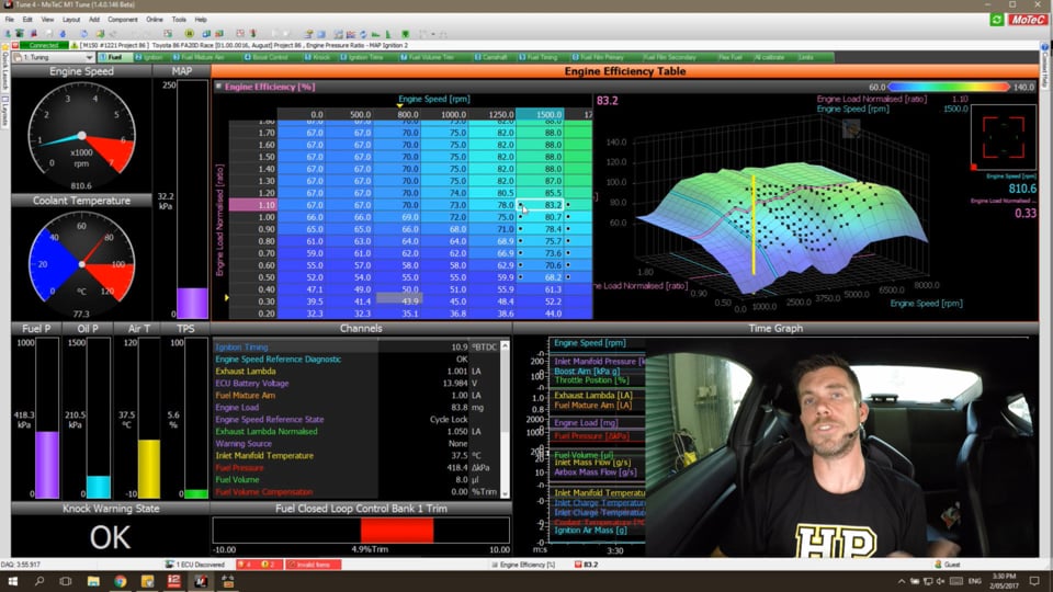
| 11:49 | So there's a couple of things we need to do and we'll start, if we jump into my laptop screen here, you can see we've got our engine running. |
| 11:56 | And at the moment we've got our exhaust lambda and our fuel mixture aim being displayed on the right hand side there, and our time graph. |
| 12:05 | During warm up, the air when the engine first starts, we see the closed-loop controllers disabled, we'll talk about that shortly. |
| 12:13 | Now that the closed-loop is enabled, we see at the bottom of the screen, this little bar graph here just shows what the closed-loop controller's doing at the moment. |
| 12:20 | And you can see under the restart there, we've got a heat soak situation. |
| 12:25 | And immediately after restart, we can see that the closed-loop control is adding some fuel. |
| 12:30 | Don't worry about that, right now we'll talk about all of that very shortly. |
| 12:34 | What we're going to do is start with talking about the parameters that we need to tune and how we need to go about setting up our ECU before we enable closed-loop control. |
| 12:44 | And really, this comes down to the workflow for a standard M1 tuning job anyway. |
| 12:51 | If we go to our fuel mixture aim table, this is really important because this is one of the key inputs for volumetric efficiency based fuel model. |
| 13:01 | So we need to start by making sure that our fuel mixture aim targets are actually realistic, these are what we actually want the engine to be running. |
| 13:11 | So we can see here that in the idle and cruise areas, we're targeting lambda one. |
| 13:17 | And if we look at the wide open throttle areas of operation, we can see that I'm targeting 0.82 lambda. |
| 13:24 | And at higher RPM we're dropping that down just a touch richer to 0.80. |
| 13:30 | Again, these targets won't necessarily be correct for you but whatever you're happy running, you need to start by making sure that your fuel mixture aim table is correctly set up. |
| 13:41 | We jump back to our fuel efficiency table and the next step is to make sure that our efficiency table is correctly tuned. |
| 13:50 | Now see that the closed-loop control isn't a bandaid, so we really want to make sure that the efficiency table is as accurate as possible. |
| 13:57 | Like any closed-loop aspect of control, I'm thinking here, boost control, idle speed control. |
| 14:04 | What we really want to do is give the ECU as little work to do as possible. |
| 14:09 | Now if our base table is accurately tuned, this should mean that under most conditions, the closed-loop control strategy has little to no work to do. |
| 14:20 | If our volumetric efficiency table is a complete mess and we've got large errors in there, then obviously the closed-loop control is going to be trying to correct those errors. |
| 14:29 | And this is where the closed-loop control's ability to do a good job can start becoming a problem. |
| 14:35 | In particular, and this is a scenario we'll talk about again shortly. |
| 14:39 | In particular, where we see this problem is where we have two adjoining cells. |
| 14:44 | And the first cell that we run through, let's say under wide open throttle operation in a ramp room, the first cell is a little bit too rich. |
| 14:53 | So what happens there is that the ECU under closed-loop control will remove fuel to correct that rich air-fuel ratio. |
| 15:00 | If the next cell however is lean, what we find is a situation where as the ECU moves through and to the lean cell, it's already got a negative trim with the closed-loop control and what this means is that we end up with the air-fuel ratio actually going leaner than we want. |
| 15:18 | So it's really important to understand how errors in our volumetric efficiency table can affect the closed-loop control's ability to do a good job. |
| 15:27 | While I've been talking, if we just look at our closed-loop fuel trim, you remember that we started there with something in the region of about 12 or 14% after that hot restart. |
| 15:37 | Now you can see that while I've been talking, that's come back down to four and a half percent. |
| 15:43 | So this is just another indication here of the fact that there are some aspects to do with the heat soak situation that result in a need for some additional fuel trim that dissipates over time. |
| 16:00 | Alright, so let's go and look at the set up for our closed-loop fuel control, and we can find that on the engine systems workbook, and what we want to do is go to our closed-loop fuel worksheet. |
| 16:12 | I'm gonna go through the options that are available here. |
| 16:15 | What I'll do is I'll just fullscreen this so we can see everything. |
| 16:20 | Let's just start with our parameter here for our closed-loop mode. |
| 16:24 | So this is simply where we can enable or disable the closed-loop operation, so by default this will be disabled. |
| 16:33 | If we want to turn our closed-loop control on, this is where we can do that. |
| 16:38 | Now, we'll go through each of these parameters. |
| 16:42 | There's a fuel closed-loop fault delay parameter, which at the moment, you can see is set to 60 seconds. |
| 16:50 | Now, this is really important, what it means is that if the fuel closed-loop trim sits at its limit, which we can configure for this period of time, then the ECU would decide that the sensor is faulty and it will shut down closed-loop fuel control. |
| 17:10 | Now, this is going to depend a little bit on the trims that we allow. |
| 17:16 | So if we've got very, very tight trim limits, so we aren't allowing, let's say for example, a maximum of plus or minus 5% fuel trim at any point in our efficiency table. |
| 17:26 | It is very likely under a hot restart condition like we just saw that we end up tapping out on that maximum trim of plus 5%. |
| 17:36 | The actual air-fuel ratio will still possibly be leaner than our targets so the ECU's trying to add fuel. |
| 17:41 | It's on that limit and if it sits there for that fault delay period, then it will disable closed-loop control. |
| 17:48 | So one of the things to watch. |
| 17:49 | You can always see what's going on, if we look at our closed-loop diagnostic channel up above. |
| 17:55 | I'll just move this over so we can see what that's saying. |
| 17:58 | And at the moment that is saying single sensor. |
| 18:03 | That's what we've got here, it's a four cylinder engine with one single collector lambda sensor. |
| 18:09 | If we had a V configuration engine with a dual lambda controller, dual lambda to CAN unit for example, then what that will do is actually allow individual fuel bank control, one per sensor. |
| 18:23 | And if one of the sensors reads faulty, then what it will do is revert initially to that single sensor so it'll make all of the control changes, closed-loop changes, based on one sensor to one sensor that is still reading. |
| 18:37 | And then if that goes faulty, then the system will be disabled entirely. |
| 18:42 | Let's move back down in order though, our next parameter here is our closed-loop coolant temperature threshold. |
| 18:50 | So essentially what this means is if the engine coolant temperature is below this point, which I've got set to 50 degrees centigrade, then we can, we will disable or ignore closed-loop control. |
| 19:00 | Now again with the advances in these lambda controllers, the requirements for disabling the closed-loop control during warm up enrichment, probably a little bit moot these days. |
| 19:13 | We can't actually use the sensor, the wideband control just about from initial startup or as soon as the sensor comes online. |
| 19:21 | Moving down we also have some parameters for minimum engine speed and minimum inlet manifold pressure where the sensor will actually be able to work. |
| 19:32 | And again, this really comes down to exactly where we want the sensor's control to be functioning. |
| 19:39 | Okay, we'll move down and we're going to look at two of the really critical tables here or parameters here. |
| 19:45 | We have fuel closed-loop control trim maximum and minimum tables. |
| 19:50 | So this defines how much control our closed-loop system is allowed to apply. |
| 19:55 | Now by default, these are actually defined as single parameter so it's just a single value. |
| 20:03 | However, what we can do is, by pressing the A key, we can go into our axis setup. |
| 20:09 | And if we want, we can develop a full three dimensional or two dimensional table with axes of engine speed and inlet manifold pressure. |
| 20:17 | And that's exactly what I've got here, we can see it displayed graphically but I'll just remove that for the moment so we can see the whole graph. |
| 20:25 | So this is our minimum trim limit. |
| 20:28 | We can jump across to our maximum and essentially you can see we've got just about exactly the same table set up there. |
| 20:37 | So why do we want this? What's this actually going to do? What we need to do is consider if our volumetric efficiency table is well developed which we're going to assume you've done your job and it is where we're likely to see the biggest errors and hence where are we likely to need the biggest control. |
| 20:54 | And generally, we're going to find that the biggest errors I'm going to creep in during a hot restart heat soak situation. |
| 21:02 | So we're gonna see that these are idle and possibly also transitioning through into our cruise areas. |
| 21:10 | As our air flow increases, particularly, if we go up to wide open throttle, we do a full throttle pull through the rev limiter. |
| 21:18 | Then the higher air speed, the higher velocity that we're going to get under those conditions and the higher mass air flow. |
| 21:24 | While we can still see variations based on heat soak, they tend to be greatly reduced so we don't tend to see the requirement for such dramatic changes. |
| 21:34 | So what I tend to do is develop my tables around the scenario. |
| 21:38 | So let's look at what I've got here, up to 3,000 RPM and 60 kPa, we can see if I look at the negative trims, I'm allowing the ECU to pull out minus 15%. |
| 21:49 | That's quite a broad amount of adjustment that's available there. |
| 21:53 | Slightly higher up in the overrun areas, high speed cruise areas, we're allowing 10% trim. |
| 22:00 | And then if we transition up into positive manifold pressure, and remembering that this engine runs around about a 160 kPa. |
| 22:08 | In that area, you can see that I've limited the trim down to minus 5%. |
| 22:13 | There's a couple of reasons there, as I've already said, we shouldn't, if we've done our job properly, need too much trim under those conditions and also that limits the potential if something does go wrong, even without diagnostics in our CAN, communications of the diagnostics from the wideband sensor, if something was to go wrong, it limits the amount of control that we can possibly have under those wide open throttle conditions. |
| 22:38 | And understandably, if we allowed a really large trim and maybe the ECU ended up trimming out 15%, this could damage the engine. |
| 22:46 | So that's how I've got my table set up. |
| 22:48 | Of course, there's no requirement to set them up exactly how I've done. |
| 22:53 | Just a description of why I've done what I've done. |
| 22:56 | But by default this will just be a single value which will be applied regardless of manifold pressure and regardless of engine speed. |
| 23:06 | If we want to essentially disable the control for any particular reason, we can set the value to 0% by positive and negative, we wanna make sure we adjust both of those tables and that will limit the control. |
| 23:23 | Basically take us back to just the raw value that's coming from our volumetric efficiency table. |
| 23:31 | There is also the ability to have a fuel closed-loop control trim average gain and decay, and this is essentially a form of long term trim. |
| 23:41 | So what it's trying to do here is look at our, if we've got a continual positive trim everywhere in the table, what it's going to do is try and step that up and remove that positive trim so it makes the short term trims a little bit less, the requirements for the short term trims will come back to closer to zero. |
| 24:04 | This is sort of similar in a lot of ways to how a lot of O.E. engines work with a short term and a long term fuel trim. |
| 24:12 | I’ve actually got that disabled, so I've got the gain set to zero there. |
| 24:16 | So this isn't actually doing anything in our Toyota 86. |
| 24:21 | We'll just jump back out of order and there's a couple of other things that we need to discuss. |
| 24:25 | First of all, we've got our fuel closed-loop control trim gain. |
| 24:31 | So what this does is it defines how much of an error between our lambda target and our measured lambda is going to be corrected in one iteration or one change. |
| 24:42 | So if we have this set to a 100%, then the entire error will be corrected in one update. |
| 24:48 | Now this sounds like the ideal scenario. |
| 24:52 | Why would we not want to correct all of the error in one single update? However, in reality what I tend to find, at least in the applications I have used this, is if we set the gain to a 100%, we tend to end up with the closed-loop control oscillating. |
| 25:09 | So I've settled on a value here of 80 which, actually as we can see is also the recommended point to start with. |
| 25:16 | This tends to do a really good job without running the system into instability and creating that oscillation. |
| 25:24 | Okay, and the last aspect we need to discuss here is our fuel closed-loop period table. |
| 25:32 | Now probably if you're not aware of this table already and how it works, that's not going to mean very much to you. |
| 25:39 | Well you can see is we've got a two dimensional table here and we've got exhaust mass flow as our axis. |
| 25:47 | We can see at the moment, we're sitting at idle and our exhaust mass flow is sitting somewhere around about two grams per second. |
| 25:53 | But this table defines how quickly the lambda control will update. |
| 26:01 | Now what we need to understand is how this system works. |
| 26:05 | What the system's going to do is it's going to sample the exhaust air flow and it's going to measure the lambda or air-fuel ratio of that sample gas. |
| 26:15 | It's then going to decide if the air-fuel ratio is richer or leaner than our target and if it's away from our target, we will make the appropriate change. |
| 26:23 | That will affect the fuel volume being delivered by the ECU. |
| 26:28 | Now there is a transit or transport time, or latency, if you like, between that change being made and the actual air-fuel ratio in the exhaust system also changing. |
| 26:42 | And this will depend on our engine speed or our mass air flow. |
| 26:47 | So what I mean by this is, at idle, we've got relatively low exhaust mass flow. |
| 26:52 | The engine's not moving a lot of exhaust mass and this means that we need a slower sample time. |
| 27:00 | At high RPM, high load on the other hand, we've got a lot of inlet mass flow, hence, we've also got a lot of exhaust mass flow, that latency is reduced, so the time it takes for a change to actually change our fuel delivery to actually be read by the sensor, is dramatically reduced. |
| 27:18 | So we need to develop this table and if we haven't done this properly, we're going to end up with our closed-loop fuel control not being as effective as it could be. |
| 27:29 | Let's look at what I've got in this table and we can see, again, we're sitting around two grams per second. |
| 27:35 | We can see I've got a value in this table of 2500. |
| 27:38 | This is in milliseconds, so 2.5 seconds. |
| 27:41 | What this simply means is that the ECU will sample the exhaust gas, it will look at the lambda, it will make a correction based on the error. |
| 27:49 | And then it's going to wait two and a half seconds before sampling again to see if the correction it made was effective. |
| 27:56 | Let's just go back to our time graph and we'll see this in action. |
| 28:01 | So we can see if we look at our purple channel down here, fuel closed-loop state. |
| 28:08 | This is the little spikes that we see here are the updates. |
| 28:12 | So every two and a half seconds, we see a spike and that's where it's making any adjustments. |
| 28:17 | So I'll just pause that for the moment and, if we look here, so at this particular point, 800 RPM was sitting at idle, I'm just going to the center of that particular spike and you see it's taking a sample, that's what it said, the state has changed the sample, and if there's an error or a difference, it will be corrected during that sample, and then we can see that it continues to say wait, and we get another sample here. |
| 28:47 | Now, let's also, if we look at what's happening with our closed-loop control, in between while it's waiting, you can see it's sitting at 5.8%. |
| 28:54 | After that sample, it decided there was a need to add a little bit of fuel, so we've gone to 6%. |
| 29:02 | So that's, 'scuse me. |
| 29:03 | That's how the closed-loop period table works. |
| 29:08 | And it's important to get that table developed so that our closed-loop control is going to work accurately. |
| 29:16 | So we can see here at low RPM, we've got a very low exhaust mass flow, I should say. |
| 29:21 | We've got a long delay, a long period. |
| 29:25 | However, when we are operating at wide open throttle at high RPM, we're going to be up in the higher exhaust mass flow areas. |
| 29:33 | And we can see that at this point we've got a delay or a period of only 200 milliseconds. |
| 29:39 | So it's sampling much faster. |
| 29:42 | So if we got this table wrong, what it's going to end up doing is causing an oscillation in our fuel control. |
| 29:49 | So, I'll try and see if I can introduce that. |
| 29:53 | So what I'm going to do here, we'll just unpause our table here, our time graph. |
| 29:59 | And what I'm going to do in our idle areas, I'm just going to take this period down to a 100 milliseconds. |
| 30:05 | Now what we're going to see is our fuel trim, is working exactly as I'd hoped. |
| 30:11 | If we look at what's going on here, you can see that our closed-loop fuel trim is now oscillating because it's trying to update what it's doing. |
| 30:19 | I'll just pause it so we can talk about it. |
| 30:21 | What it's doing is, it's taking a sample, it sees that the air-fuel ratio is lean. |
| 30:26 | So it's adding fuel straightaway though before that change can take effect and sampling again. |
| 30:31 | Lo and behold, the air-fuel ratio is still lean, so it's going to add more fuel, and this just continues to repeat. |
| 30:37 | By the time the change actually takes effect in the exhaust gas, we've gone way past our set point and the air-fuel ratio is rich. |
| 30:45 | So again, if we just fullscreen our time graph, we can see that the oscillation sets up in our closed-loop fuel trim. |
| 30:53 | So there's an instability there that's also understandably shown up. |
| 30:57 | If we look above this, we have our exhaust lambda in yellow. |
| 31:01 | So that's our measured exhaust lambda and we can see the orange line is our mixture aim. |
| 31:08 | And we can see that our, we can see that our exhaust lambda in yellow is oscillating both rich and lean above our line. |
| 31:16 | So it's really important to make sure that our period table is set correctly. |
| 31:23 | If we haven't got our period table set correctly then our closed-loop control is going to become unstable. |
| 31:30 | And there's a few reasons that our closed-loop control can become unstable. |
| 31:35 | We need to understand the interaction so we can decide what change needs to be made. |
| 31:41 | So the first one is if our gain is set to high. |
| 31:45 | I've already talked about that. |
| 31:47 | If we have a gain that's potentially too high, this can try and correct too much of the error in one go and the result is this can set up an oscillation or an unstable closed-loop trim. |
| 31:58 | The other aspect is if our period is set incorrectly and it's too short, this will give the same scenario. |
| 32:05 | And then of course, I've also talked about our table, our volumetric efficiency table tuning as well. |
| 32:14 | So if we've got adjacent cells that are both rich and lean, then our closed-loop control is gonna really struggle to correct that and this can also result in oscillation. |
| 32:23 | So it's really important when we're looking at the results of our tuning to understand exactly what we've got going on and why we've got an oscillation or an unstable control and what we need to change in order to fix that. |
| 32:37 | When we're developing our exhaust mass flow table, it's important to make sure that we have data that spans the entire exhaust mass flow range. |
| 32:47 | So what I'm going to do is we'll just unlock our layout, and I'm going to add exhaust mass flow into our time graph so we can log that. |
| 32:57 | And we'll do a quick run on the Dyno and then we'll be able to see what our exhaust mass flow is. |
| 33:04 | So I like to do this just to give me a bit of an idea on the range that I need for the axis value. |
| 33:14 | So we'll just add exhaust mass flow, and I probably don't need that spanning out to a thousand so let's just take that to 400 grams a second and we should be good to go. |
| 33:28 | So we can see that's currently sitting at 2.4. |
| 33:31 | What I'll do right now is we'll just do a full run on our Dyno. |
| 33:36 | Just get us up into fourth gear in a second, we'll just do a full run up to the rev limiter until we are at gear change point. |
| 33:45 | And we'll have a look at what this data shows us. |
| 33:49 | So during this run, we can actually watch the screen on my laptop here. |
| 33:56 | We'll pause this afterwards but it'll give us a good opportunity to just see exactly what's happening. |
| 34:02 | In particular, we can see our exhaust lambda versus our target. |
| 34:07 | We'll be able to see our state, closed-loop state and you'll be able to see all of the sample periods become a lot tighter as the RPM increases. |
| 34:16 | And then, of course we'll be able to see what the actual closed-loop control is doing at any particular point. |
| 34:22 | Alright, just go to full throttle and we'll do a run now. |
| 34:26 | Just allow everything to stabilize and let's do our run. |
| 34:45 | Alright, let's just allow that to cycle over and we'll have a talk about what we've got. |
| 34:49 | We've actually just got some great data there explains exactly some of the aspects I'm talking about here. |
| 34:54 | Our first task though was to have a look at our exhaust mass flow. |
| 34:58 | And we remember that we had a value of about 2 grams per second at idle. |
| 35:02 | And we can see that at 7,400 RPM, we've got an exhaust mass flow of 260 grams per second. |
| 35:10 | So if we close that down, we can see I've actually gone to 350. |
| 35:14 | I've gone a little bit past that, maybe I'm a bit optimistic on what power I expect to be able to get out of this in the future. |
| 35:20 | But it's important just to make sure that we're at least spanning that range. |
| 35:23 | Generally, when where higher RPM, higher exhaust mass flow, because we've got less latency without changes, we can close down that period quite dramatically. |
| 35:36 | Generally, somewhere around about a 150 to 200 milliseconds at high exhaust mass flow should give us relatively good control. |
| 35:44 | It's down in the lower exhaust mass flow area that we need to be a little bit more careful. |
| 35:52 | And you can see that I transition two, 2,500 obviously very, very slow. |
| 35:57 | Could probably actually do to speed that up a little bit. |
| 36:01 | We can see that as we transition down into the cruise and idle areas. |
| 36:05 | The period changes quite dramatically. |
| 36:08 | Let's have a look now at our graph. |
| 36:10 | I'll just fullscreen there again and we'll see exactly what was going on during our run. |
| 36:16 | So first of all, let's look at the settle point. |
| 36:18 | So this is before our run, we're sitting at 1900 RPM, a 110 kPa of boost pressure. |
| 36:25 | And you can see that yellow line which is our measured lambda sits on our target pretty much perfectly. |
| 36:33 | We can also see that our trim at this point is pretty much non-existent. |
| 36:36 | We've got a trim of 1.5%. |
| 36:39 | So this is kind of like under wide open throttle this is kind of what I'd like to see. |
| 36:44 | I'd really like my trims to be sort of plus or minus about one, maybe 2% maximum. |
| 36:49 | Really, again, indicates we've done a good job on our efficiency table in the first place. |
| 36:53 | Now, a point there I noticed during this run though that's worth having a look at, here, is what's going on as we ramp up onto positive boost in our lambda target changes. |
| 37:05 | And in particular what we can see here is that our air-fuel ratio is, or our lambda is quite a lot richer than our target. |
| 37:14 | In this case we can see that we're about .83 lambda versus our target of .87. |
| 37:19 | So we see this straight away the ECU response to this by trimming minus 5%. |
| 37:27 | Now as we move through though, that minus 5% trim is still active. |
| 37:31 | We can see here as well, if I'm not drawing too many circles on the screen, we can see exactly where each sample is being taken because we're looking at our fuel closed-loop state on this time graph as well. |
| 37:43 | We can see that the closed-loop trim stays at minus 5%. |
| 37:49 | And now we've moved in to an area on the volumetric efficiency table where our fueling was probably pretty much on point. |
| 37:57 | So we can see that we've actually ended up going lean. |
| 37:59 | So I'll just get rid of those little circles on our screen. |
| 38:04 | So we can see at this point here, now our measured air-fuel ratio is 0.84 and our target is 0.81, and we've got a negative 4% trim. |
| 38:15 | When we're reading this data, it's really important to take in everything that we're looking at. |
| 38:19 | When I see something like this, I'm much more inclined rather than saying, Oh yep, there's a problem in my fuel table here, my efficiency table, and I need to go to this particular point, 3600 RPM and a 147 kPa and I need to correct that point, I need to add 3% fuel into that point. |
| 38:40 | If we actually look at the data, what it's telling us is that we're around about 3% leaner than our target. |
| 38:46 | But our closed-loop trim at that particular point is also removing 4% fuel. |
| 38:51 | So our volumetric efficiency value at that particular point is probably correct and the real issue is probably more likely to be due to what happened here, where we ended up too rich. |
| 39:04 | And possibly also the fact that our period around this point in our table as we are climbing up on to boost, is possibly a little bit too close. |
| 39:13 | So it's not actually allowing sufficient time for the change to take effect before it's making its next update. |
| 39:22 | Okay, so we'll shut that down now and the other aspect to understand here is that we can utilize our closed-loop fuel control to help us when we're actually performing our tuning. |
| 39:36 | So in particular, if we are tuning an engine that we've never seen before, we're really starting to develop our efficiency table from scratch. |
| 39:45 | Obviously, under those conditions, there's a pretty good chance that at some points our air-fuel ratio or lambda maybe well off our target while we're getting our efficiency table into order. |
| 39:57 | Now this is where I like to actually use the closed-loop trim, closed-loop fuel control in order to help me get the lambda closer to my target straight away. |
| 40:08 | I'm gonna have a look at how we can do that. |
| 40:11 | Now also I mentioned that I will move into some questions and answers really shortly. |
| 40:15 | So if you do have anything you would like me to cover of, please ask those in the chat and I will answer those shortly. |
| 40:25 | Alright, what I'm gonna do is I'm just going to, we're going to our laptop screen. |
| 40:29 | We'll just get back into fourth gear, and we'll bring ourselves up to around two and a half thousand RPM. |
| 40:41 | Okay so, when we're initially making our tuning changes, if we're starting with an engine where we've gotten no existing map. |
| 40:51 | Now it's a really good idea to start with quite a large amounts of trim control. |
| 40:57 | And this is because we can expect under these conditions to have quite large errors. |
| 41:02 | So when I'm first starting to tune the VE table, I may start with a positive and negative trim of 25% limit. |
| 41:11 | This has got a quite a broad range of control. |
| 41:14 | Now in this case, we've got a relatively small error but what I'm going to do is just get rid of all of these little marks, so we know where we've been. |
| 41:26 | And just for the sake of this testing, let's go and add 10% fuel to all of this region. |
| 41:35 | So what this is going to do is it's going to help us sort of replicate an engine that hasn't been tuned before. |
| 41:42 | As I'm moving to an area that I've just added 10% to, we can see how closed-loop control is removing just around 9% fuel. |
| 41:52 | How we can use this is, as we're tuning our VE table, our air-fuel ratio or lambda is always going to track really closely to our target and that's because the closed-loop control is taking up any error. |
| 42:04 | Now, that doesn't mean that my efficiency table is now correctly tuned and that's an important distinction to make. |
| 42:10 | Here we've got the ECU doing the work for us but what it can do is help keep our lambda on target and take care of any large errors. |
| 42:19 | What I can do now is just get myself central in the cell that I'm interested in, and we're using our little target to decide when we're exactly in the middle of the cell. |
| 42:29 | And then I can simply press the Q key or quick lambda key, and that will lock in whatever change the closed-loop control is making at that particular point in the table. |
| 42:41 | You can see as I do that, our closed-loop control zeros and it's actually established a minus 2% trim again. |
| 42:49 | We may have to, in some instances, go through a couple of iterations of that. |
| 42:53 | But it's a very quick way, rather than manually correcting our air-fuel ratio, it's a very quick way of correcting that automatically using the ECU's closed-loop control. |
| 43:04 | Now what I'll do is I'll just bring our throttle up and we'll come into our next cell at 0.9. |
| 43:10 | So again, we've got approximately that same error. |
| 43:12 | Probably not that surprising considering I added 10% to all of these cells. |
| 43:18 | Again, I'll just press Q. |
| 43:20 | We can see that that error is removed. |
| 43:22 | We can see that our closed-loop control is reset to zero and that now means that that efficiency site is tuned. |
| 43:30 | So when we're looking at whether our efficiency site is correctly tuned, what we're looking at is what the closed-loop control is doing at that point along with what our fuel mixture aim and our measured lambda values are doing. |
| 43:44 | Generally, while we can see them vary around a little bit, we should, under steady state conditions, be able to get these within 1%. |
| 43:51 | Let's just go through and open the throttle again and we'll do one more cell. |
| 43:57 | Again, that's going to end up with our closed-loop control establishing around about minus 9%. |
| 44:02 | I press Q, that's locked in that change and again we're set to zero. |
| 44:08 | It's a very helpful way of using our closed-loop control to make sure that our lambda is on target while we're developing our fuel table, our efficiency table from scratch. |
| 44:19 | And the key point here is, while in that particular application, that particular example, I'd added fuel so we were rich. |
| 44:27 | Obviously that's a safe situation. |
| 44:30 | Quite likely, we can be in the reverse situation where we're developing our efficiency table from scratch, we may find that as we increase our load or we increase our RPM, move out into zones that we haven't previously tuned, we may find that we end up lean. |
| 44:45 | And particularly as we increase the load and RPM on a powerful engine, that can be a potentially dangerous scenario. |
| 44:52 | So how I tend to use the closed-loop control under those conditions is let that do the work of correcting the errors. |
| 44:59 | And this saves us a little bit of time because, conventionally, what we would do is potentially increase our throttle, move into an untuned site, look at that site, see that the air-fuel ratio is leaner than our target. |
| 45:12 | And if the air-fuel ratio was significantly lean, then the safe option would be to back off our load, go back into a safe tune cell, make a change to the cell that we've just looked at, and then go back into the throttle and try again. |
| 45:26 | So this basically does all of that work for us and help us build up our table, our efficiency table much quicker. |
| 45:34 | I still use the techniques that we taught in the practical Dyno training course though, while we're going through the steady state tuning. |
| 45:43 | So if I'm moving up a load column and I've just tuned a cell, at perhaps, 20 kPa of boost pressure and I've ended up with a value of 88% in that particular cell, and I look above in the next cell at the higher load maybe 40 kPa of boost is 60, well, I know that's probably not very realistic. |
| 46:03 | So rather than moving into that cell with the expectation that the air-fuel ratio is going to end up lean, what I'll do is tend to extrapolate the changes that I'm making out into those untuned areas at the same time. |
| 46:16 | It's all about minimizing our time on the laptop, our time on the Dyno and also minimizing the risk for the engine because we're making sure that our air-fuel ratio is always as safe as possible. |
| 46:27 | We're not going to be exposing the engine to a potentially dangerous air-fuel ratio. |
| 46:33 | Now, if we are using that technique which I've just talked about where we're allowing a broad range of control, perhaps as much as plus or minus 25% trim, it's important once you've developed your efficiency table, to go back and reduce that to something a little bit more sensible in those higher load areas as we've already discussed. |
| 46:56 | Alright, we'll go and have a look at some questions now. |
| 46:58 | So again, if you do have any more questions, please ask those and I'll deal with them when I can. |
| 47:07 | TDE Champ asked, "Is the exhaust mass flow "calculated value in the period table?" Yes it is, it's calculated based on the inlet mass flow. |
| 47:16 | The way the volumetric efficiency system works is, our VE numbers are actually being used for the ECU to calculate an inlet mass flow value and in turn the exhaust mass flow value is calculated from that. |
| 47:33 | Adamtunes asked, "It seems like we're just monitoring "and making sure that certain parameters "are working as they should." Yes, under perfect conditions, that's correct. |
| 47:42 | And under perfect conditions, we should expect our closed-loop control to be doing very, very little to nothing. |
| 47:50 | That's the ideal I'd like to see our closed-loop control, and under most circumstances, doing perhaps no more than plus or minus two or 3% work. |
| 48:01 | The reason we are wanting to potentially use closed-loop control, as I've discussed earlier in the webinar, however, is under some scenarios, we can get atmospheric or ambient conditions change that aren't correctly accounted for in the fuel model. |
| 48:15 | Where if we aren't using closed-loop fuel control, we can end up with significant errors in our air-fuel ratio. |
| 48:23 | While under cruise and idle conditions, these may, may not be dangerous to the engine. |
| 48:27 | They won't be. |
| 48:29 | What it can end up doing is affecting the drivability of the engine, particularly the scenario that I've discussed, that we see quite frequently, where the engine will run lean after a hot restart. |
| 48:44 | That can end up with the idle quality suffering. |
| 48:47 | If the air-fuel ratio is lean enough, it can end up creating a situation where the engine can stall, and certainly it won't be as responsive to the driver. |
| 48:56 | It's just a system which we can use in order to maintain really stable control under varying conditions, once the engine has left the Dyno, once it's left our control. |
| 49:08 | Alright, that looks like it's taken us to the end of our questions. |
| 49:11 | As usual, if you do have any more questions that pop up, please ask those in the forum and I'll be happy to answer them there. |
| 49:18 | Thanks for joining us, I hope you've enjoyed today's webinar, look forward to seeing you all on the next one. |


