187 | Body electronic circuits to include in your race car
Summary
When you're building a dedicated race car, the complete factory wiring harness is often removed, with only the most minimal required systems reinstated, usually with new dedicated wiring harnesses. In this webinar we'll have a look at some of the common body electrical circuits your race car might need, how we go about designing the circuits to run them, and how we construct the body wiring harnesses and sub harnesses.
| 00:00 | - Hi guys, welcome along to today's online members only webinar. |
| 00:05 | Really really awesome to have you along. |
| 00:08 | Today we're going to be talking about wiring up some of the body electronic circuits if you're building a race car. |
| 00:15 | So we're not going to be looking at EFI systems, for a bit of a change, we're going to be looking at some of the body harness circuits and how we're going to wire those up. |
| 00:23 | And we're going to look at it from the perspective of if you were building a race car, say a club level race car, or a weekend warrior in your own garage, how you can achieve a good tidy result of those critical body electronics circuits without spending an absolute fortune. |
| 00:39 | So the circuits that we're going to go through are your headlights, your brake lights and you indicators, because they are all critically important and required by probably most club level racing bodies. |
| 00:51 | We're then going to have a look at what you're gonna need when it's raining, which is gonna be your wipers and a defogger. |
| 00:56 | And last of all we're gonna have a look at the power windows as well, as anyone that's got a club level race car and is loading it on and off a trailer is going to know that having your power windows, or in fact any windows in your car working does become really important. |
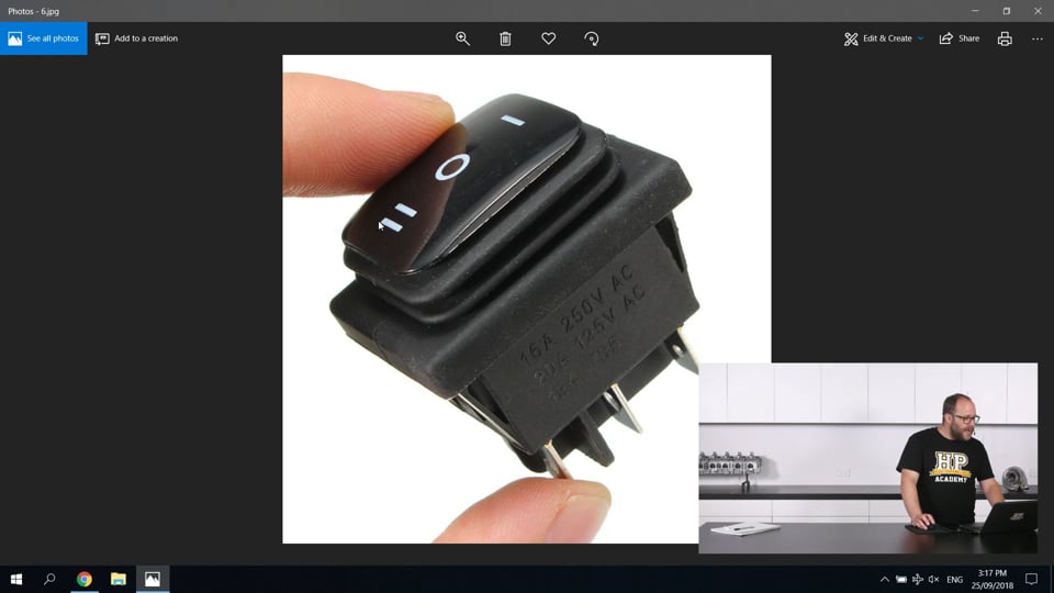
| 01:12 | So if we pop over to my laptop super quickly here, the first thing I want to talk about is a rocker switch like this, which is a particular type of switch called a DPDT switch. |
| 01:24 | And the DPDT stands for dual pin or dual pole, and dual throw. |
| 01:32 | What that means is there's actually two ways that you can actuate this switch. |
| 01:36 | You can press up on the top here to actuate it one way, or you can press up in the bottom to actuate it the other way. |
| 01:41 | And its natural position is sitting here in the middle not actuated either way. |
| 01:46 | Now these are available in a couple of different configurations. |
| 01:50 | For the switching action up here they can be what is called a momentary switch, where if you press either side here, you have to hold it down because if you release pressure, it's actually gonna pop back to its default state of nothing being connected. |
| 02:03 | They're also available in a momentary on one side configuration and a fixed switch on the other side configuration, that means one side's momentary, and when you press the other side down it'll actually stay in that position. |
| 02:15 | And the last configuration which you've probably already guessed is a fixed switch in both positions. |
| 02:22 | So that is you can press the top here to switch it that way, it'll stay in that direction, you can flick it back to the default position which is nothing connected or you can press down the bottom here to switch it the other way. |
| 02:35 | Now you can see we've got three terminals on the bottom of this switch here, and the reason I'm talking about this switch first is we're actually going to look at the body electronic circuits from a perspective of using these switches to control all of them. |
| 02:49 | So we're gonna look at the different ways that you can use a DPDT switch like this to control all those different circuits that we've talked about. |
| 02:57 | The aim behind that is, you can actually build a switch panel for your race car that's going to end up looking very very tidy. |
| 03:04 | Because you'll be able to have nice uniform switches, really easy to get them evenly spaced and nice and easy to replace one if any of them ever go bad. |
| 03:13 | So talking about our three pins down here, just wanna talk about the way that they get connected when we actuate this switch in particular ways. |
| 03:21 | So sitting here with the switch in the totally default position, nothing is connected, all these pins are completely isolated from one another. |
| 03:31 | If we were to push on the top of the switch here. |
| 03:34 | What would actually happen is this centre pin here would get connected to this bottom pin. |
| 03:39 | You can think of it as coming through on a diagonal like this. |
| 03:43 | As you push this, actually a wee slider gets flicked across inside the switch and connects these two pins. |
| 03:48 | Similar to that, it's exactly the same when you actuate it in the other direction when you push down here, that wee toggle slider gets pushed the other direction and connects these two pins. |
| 04:00 | Now there is one last detail that's really really important about these switches, is we've got our three pins here, but there's actually a whole nother set of pins around the back of the switch here that you can't see in this image. |
| 04:11 | And they work exactly the same as the three pins on this side, however they are completely isolated from these three pins. |
| 04:20 | So the best way to think about this is you've actually go two switches in the one housing here that you actuate from the single rocker. |
| 04:27 | And you're going to see, when we talk about our circuits in a minute, why that's really important, as we're going to use a single switch to actually do a couple of different jobs. |
| 04:37 | And allow us to actuate a couple of different relays or flashes in different ways to get the result that we're after. |
| 04:44 | Cool so the first circuit that we're gonna talk about is going to be our headlights, and how we can use a DPDT switch to actuate our headlights, sorry actuate, turn on our headlights. |
| 04:57 | Now headlights for a race car, it is really important to probably have both the low beam and the high beam of your headlights available. |
| 05:06 | So the headlights we're talking about here are going to be reasonably conventional headlights that have either a separate low beam and a high beam bulb or they could have actually the low beam and high beam filaments in the same bulb but they are completely separate circuits. |
| 05:21 | So if we have a look at this wee circuit diagram that I've drawn out here. |
| 05:25 | I do apologise for my horrific handwriting. |
| 05:28 | Just talk about a couple of the elements that we've got here and explain the circuit diagram and how they work. |
| 05:35 | So up here I've drawn the back side of our DPDT switch. |
| 05:40 | And you can see here we've got that centre pin and the pins on either end and then this dash line down the middle just reminds us that these pins are isolated from one another on either side. |
| 05:52 | If you'd seen, we've got a previous webinar talking about relays, so if you're a little unclear on the operation of relays, that's gonna be a really good watch. |
| 06:03 | But simply a relay is an electrically actuated switch, so we're going to use our DPDT switch to actuate our relays which is then actually going to pass the high power side of the circuit, down to our headlights here. |
| 06:18 | The way that I would approach wiring up the headlights in our club level race car to keep it a nice low buck system is like I've got pictured here. |
| 06:28 | We've got our DPDT switch. |
| 06:30 | What that's going to do is it's going to take our 12 volts from our charging system, we're going to feed the 12 volts into the centre of both sides of that DPDT switch. |
| 06:41 | It's essentially two different switches that we're feeding the 12 volts into both sides of. |
| 06:48 | Then we're going to look at our main power supply relay here. |
| 06:51 | So this is the relay that when it gets turned on, is actually going to supply power down to our headlights. |
| 06:57 | The way that is wired up is we actually take a feed from that DPDT switch from either side, either pole of that switch, they get connected together and they actually power the switching coil of this relay. |
| 07:12 | What that means is that when we flick this switch in either direction, it doesn't matter, this relay is going to close and it is going to supply power down to this relay here. |
| 07:25 | Now this is the important bit with using a DPDT switch for our switching, is that we've got the other side of the switch here that we can use to our advantage to switch this relay here. |
| 07:38 | Now in the default position, so this is, we've got a relay here that's called, it's what's called a changeover relay. |
| 07:45 | So that means when you power this relay, it changes over, the input of the relay either comes out either of these two pins, and when you power the switching coil it'll flick over and it'll power the other pin. |
| 08:00 | So the default position which is with our relay unpowered, when we turn our headlights on, the power is, this power supply relay is going to close, the power's gonna come down here, it's gonna come through our relay which is in its default position, and it's gonna head to our low beam headlights bulbs, and that's gonna turn our low beams on, which is probably a pretty good thing. |
| 08:23 | Exactly what we want. |
| 08:25 | So this would be, if I was building a switch panel for the car, I would probably have it so when I actuate the switch, the rocker switch in the down direction, this is what I would have happen. |
| 08:38 | When we actuate the switch in the up direction, our power supply relay is still going to turn on because we've got the output feed from this DPDT switch on one side, when we actuate it in the up direction. |
| 08:50 | Because they're joined together it's still gonna turn this power supply relay on, which is exactly what we want. |
| 08:56 | However now we're also going to take our 12 volts, it's going to come into the switch from this direction, we've turned the switch on in the up direction, so that's going to connect these two pins. |
| 09:08 | Our 12 volts is then going to come out through here, to our changeover relay, that's going to switch this to the power supply coming out of the other pin here, and that's then going to send the power from this power supply relay out through here to our high beam bulbs. |
| 09:28 | So you can see it's, the DPDT switch really is going to be the whole key to a lot of our body electronic circuits for this switching application. |
| 09:41 | Those two different rows of pins become really critical as we're able to switch two different circuits. |
| 09:47 | And by pairing up how they switch, and the timing of everything, we can get a reasonably sophisticated result from just the single switch and a couple of pretty simple circuit elements. |
| 09:56 | So with our switch in that default middle position there, we've got no lights, we flick it down and our low beams come on, we flick it up and our high beams come on. |
| 10:04 | So that's gonna be pretty important for all your racing needs. |
| 10:08 | Particularly if you're doing any racing that's going to involve racing at night. |
| 10:15 | The next circuit that we're gonna have a look at, that we're gonna have a quick talk about is actually gonna be the brake lights. |
| 10:22 | So brake lights obviously completely critical. |
| 10:25 | You need to be telling people when you're braking coming into a corner, really really important. |
| 10:32 | Traditionally, you're most likely aware of how they're switched, there's going to be a mechanical switch on your brake light pedal, that as you push that switch down, it's either going to actuate a switch or the pedal's going to move away from a switch. |
| 10:44 | And that's going to connect the circuit that is going to turn your brake lights on. |
| 10:50 | The reason, so there's nothing particularly complicated about wiring up your brake lights. |
| 10:54 | Brake light bulbs are also a fairly low draw so we don't really need to be using relays for any of the switching there. |
| 11:00 | However the particular reason that I wanted to mention them is quite often aftermarket pedal boxes such as floor mounted pedal boxes, things that you're installing balance bars in, they don't have a spot for a traditional brake light sensor. |
| 11:15 | So that's a mechanically actuated sensor off the brake pedal. |
| 11:19 | There's another really good option for this and if you have a bit of a google on brake line pressure switches, you're going to find something that's going to be suitable for this application. |
| 11:31 | So this is simply a little pressure switch. |
| 11:33 | Usually they've got a 1/8th NPT port on them and they're going to turn on when they see pressure on that brake line. |
| 11:42 | Really good way to get your brake light circuit operating is to use one of these switches as you can put it in the hydraulic circuit of the car, you can fit it in anywhere that hydraulic circuit is and it can be a really really good way of doing that, and keeping the wiring nice and tidy. |
| 11:56 | I have found them to be really robust as well. |
| 11:59 | I've used them on some pretty high level single seat race cars. |
| 12:03 | Some pretty professionally built formula Fords and formula threes, and they have absolutely stood up to the vibration in those environments. |
| 12:12 | So any sort of touring car application, or your weekend warrior track day car application, they're definitely gonna be good for as well. |
| 12:19 | They definitely will live. |
| 12:21 | You can find them in different switching pressure ranges and you can find them with different threads on them as well and also different connector options. |
| 12:27 | What I would recommend there is you find something with a 1/8th NPT threaded port on it cause that's gonna give you the most options for plumbing it into your brake line system. |
| 12:40 | And i would probably go with standard spade terminals on it for your club day application. |
| 12:47 | 'Cause you're not gonna need to go and find an expensive connector that's going to interface with some of the ones that are fitted to European vehicles that have a moulded connector body on them, finding those connectors can actually be a wee bit tricky. |
| 12:59 | So that's how we're going to, oh sorry there is actually one other detail I wanted to talk about with brake light wiring. |
| 13:05 | And that's using your brake lights as a rain light. |
| 13:07 | Now you're going to wanna check with your racing body or the rules of the class if this is actually an applicable thing that you can do and your car's still going to be legal. |
| 13:17 | But often race cars are going to have a rain light circuit, so this is a switch you're going to flick to put the car into a rain mode. |
| 13:26 | It could interface with any of the EFI systems and do various things there to make the car easier to drive in the rain. |
| 13:33 | But often they're going to light up a light on the back of the vehicle as well and sometimes this is going to be the brake lights of the vehicle. |
| 13:41 | Just to really increase the visibility of the vehicle from the rear, as race conditions out on a rainy circuit really do get pretty severe with the spray from all the cars on the track, your visibility gets pretty limited pretty quickly. |
| 13:57 | However if you install the switch that bypasses your brake light switch and turns your brake lights on all the time, you're going to need to check that that is actually valid with the rules of the class that you're wanting to race in. |
| 14:11 | You might have to use a different circuit in the rear lights of your car, possibly the park light circuit could be a good one for this. |
| 14:17 | But you're gonna wanna make sure that there is actually enough light output there to increase the visibility from the back of the car. |
| 14:24 | Awesome. |
| 14:26 | So the next circuit that I wanna talk about are the indicators. |
| 14:28 | So indicators are going to be pretty critically important for most race car applications, used to signal people to pass, if you've got a mechanical issue, or that you're heading into the pits. |
| 14:39 | Or if your race car's actually still road registered and you want to drive it on the road, you're going to need to have indicators. |
| 14:45 | So we'll have a talk about wiring those up. |
| 14:48 | Just pop to our overhead shot here and we've got another we circuit diagram drawn out. |
| 14:54 | So the main element you're gonna see in the middle here is what's called our flasher unit. |
| 14:59 | So the flasher unit looks actually very much like a relay and it even operates somewhat similar to a relay. |
| 15:03 | However instead of when we provide power to it, it just turning on or switching, it's going to turn on and then turn itself off in a repeatable pattern. |
| 15:14 | Thus flashing our lights. |
| 15:17 | Now there are a couple of different styles of these. |
| 15:19 | You can get thermal ones which are sort of the old school style. |
| 15:23 | So they actually work by when we apply power to them, a wee bimetallic spring in them heats up so as that bimetallic spring is heating up it gets hot enough that it actually closes a circuit, that then sends power out to our lights. |
| 15:38 | As that power's going out to our lights, it's no longer going through the bimetallic spring, so that bimetallic spring then cools down, breaks the circuit, power starts going back through that bimetallic spring, goes and closest the circuit and the process repeats. |
| 15:54 | Those are the traditional way that flashes have been implemented, and this is probably on most cars up until I'd say the mid 2000s even, they're still pretty common. |
| 16:05 | They have one benefit is that they are typically sized in such a way that if any of the indicator bulbs in the vehicle fail, the flasher unit will either no longer flash, so all your indicator bulbs will stay on constantly, or they will flash very very fast. |
| 16:23 | This is a really good way of letting you know that you do have a problem with your indicator lights, and one of them's blown and you need to replace it. |
| 16:30 | However for our race car application, I'm probably gonna say that that's not really important, as we're giving the car a good check over before every race day, so we're likely to discover if it's got any blown indicator bulbs. |
| 16:41 | So I wanna talk about the flasher unit that I've actually drawn here, which is essentially the same as a thermal unit, however they're known as an electronic flasher unit. |
| 16:51 | And instead of using that thermal circuit that I talked about, they actually use electronics inside them to control the rate of the flashing. |
| 16:58 | And what that lets us do is give us a constant flash rate and it also lets us replace our indicator bulbs down here with LED bulbs as well, that draw less current. |
| 17:10 | Those less current bulbs, those LED bulbs that draw less current, when we use those with a thermal flasher, the thermal flasher essentially sees them as a blown bulb because they're not drawing much current, and it'll flash them very fast. |
| 17:21 | However we don't have that problem with our electronic flasher. |
| 17:23 | So when you're buying an electronic flasher, you're likely to find it's got three pins and much like our relay has pins labelled by numbers that don't seem to make any sense, so do our flashers. |
| 17:35 | We've got a 49 a 49A and a 31. |
| 17:39 | So the way we wire them up is our 31 pin gets grounded, our 49 pin gets power supplied to it, and the power gets passed from the 49 pin to the 49A pin, and then out to our lights here, and the electronic flasher actually makes and breaks the circuit between these two pins here. |
| 18:02 | Now what we're doing with our DPDT switch here, which we'd probably mount sideways in our switch panel, and we would actuate it one way for the left hand indicators and one way for the right hand indicators, is we're taking our 12 volt power supply here and once again we're having it so when we actuate this switch, in either direction, it's gong to supply power to this 49 pin. |
| 18:25 | That then is going to turn the electronic flasher module on, that's going to start oscillating the connection between these two pins, that power's going to come from our 49A into the centre of our DP, the other side of our DPDT switch here, and because we've flicked it either one way or the other way, it's going to send that power out to either our right hand indicators or our left hand indicators. |
| 18:51 | Which is very much what we're going to be after. |
| 18:53 | So that's gonna be a pretty intuitive setup for your switch panel. |
| 18:58 | You're simply gonna have a rocker switch there that you can flick one way for one set of indicators and the other way for the other set of indicators. |
| 19:06 | Rightio. |
| 19:08 | Just have a quick look at my notes here. |
| 19:11 | Cool the next circuit I wanna talk about, we're getting into the stuff you're gonna need when your vehicle is, if it starts raining on the race track, what you're gonna need then. |
| 19:21 | So we're going to need windscreen wipers. |
| 19:24 | Now switching windscreen wipers, sorry that's actually quite hard to say. |
| 19:27 | Switching windscreen wipers once again, is a reasonably straightforward affair. |
| 19:33 | Windscreen wiper motors do draw a little bit of current though. |
| 19:36 | So it is likely that you're going to want to switch them through a relay. |
| 19:40 | Now for switching our windscreen wipers on you're going to want a DPDT switch that is momentary in one direction but fixed in the other direction. |
| 19:52 | And we're going to wire that switch up in such a way that the outputs of both poles of that DPDT switch are actually gonna be connected together. |
| 20:04 | And we're simply going to use the momentary switching on one side as a way of giving a quick impulse of power to our wiper motor and that's gonna get the windscreen wipers going, that's if you just need a single wipe. |
| 20:17 | Then if we actuate it the other way it's going to stay locked on and that's going to keep our windscreen wipers going. |
| 20:24 | So little bit of knowledge here about how windscreen wipers actually work. |
| 20:28 | When we give them a quick impulse of power, that motor spins and it starts moving the windscreen wipers. |
| 20:35 | Once that happens, the windscreen wiper motor actually self powers from that point onwards. |
| 20:41 | So that means the windscreen wiper's going to continue over the entire windscreen until the wipers come back to their parked position, at which point the self powering turns off and if there's no more power being supplied to the windscreen wiper motor, then there's no power to move them and they'll stay in that parked position. |
| 20:59 | However if we have switched that rocker switch to the fixed on position, power is still going to be being supplied to the windscreen wiper motor and they're going to start moving and that process is going to complete. |
| 21:11 | So wiring up your windscreen wiper motors is actually gonna be quite application dependent. |
| 21:16 | Likely you're going to have to find a factory service manual for your car to get the pin out for the wiper motor there but they are at least up until the mid 2000s, they are sort of most of them wired in pretty much the same way, it's just a matter of finding those pins. |
| 21:31 | So that's gonna be a really good way of getting another nice switch on your switch panel there to actuate those wipers. |
| 21:38 | Right the next circuit I wanna talk about is defogging. |
| 21:40 | And this is one that often can get a little bit missed. |
| 21:46 | Ah mist, yes that's a beautiful pun right there. |
| 21:49 | Can often get left out of that body electronic design. |
| 21:53 | And you might not realise you need it until you really need it. |
| 21:57 | It starts raining, race cars leak, they just do, water gets inside, the floor's hot because of your exhaust, and everything starts fogging up, and it really happens pretty quickly, and it can actually be really quite dangerous. |
| 22:11 | So a lot of racing regulations and rules will actually require you to have a defogging circuit on your car. |
| 22:19 | Now there's two ways that this is typically gone about. |
| 22:23 | So you can either have an electric heated windshield on the car, if it's available. |
| 22:30 | A lot of common vehicles that get turned into race cars, I know they're available for a lot of Hondas, my particular experience with one is with a Mazda RX-7. |
| 22:40 | You can purchase aftermarket heated windshields for them. |
| 22:43 | There's not a lot of complicated wiring involved in setting these up. |
| 22:47 | Once again they do draw a bit of current so they're likely to be supplying them with a relay but it is gonna be a case of just a momentary switch that gets flicked on and gives power to that windscreen heating circuit. |
| 23:01 | If you're using, if you've still got the factory glass in the rest of the vehicle, chances are you're going to have a defogging circuit on the rear window and it'd be a good idea to include that in the circuit as well, just to really help with your rear visibility. |
| 23:15 | The other way that this is sometimes gone about is actually to interface with the heater in the vehicle, the OEM heater. |
| 23:22 | Now often the coolant circuit to the heater matrix in the car is going to have been removed when we've turned that car into a race car. |
| 23:32 | However we can still get a pretty good defogging effect by just turning on the heater blower motor in the car, and making sure our vents are set to blow on the windscreen. |
| 23:46 | Now chances are a lot of that electronic system is going to have been removed, so you're going to need to get under the dash and physically actuate those vents to make... |
| 23:56 | Hi guys welcome back, sorry about that. |
| 23:57 | Another wee bit of a technical hiccup again. |
| 24:00 | Saw someone mentioned in the comments there, maybe we specced the wrong gauge wire for the live stream today. |
| 24:05 | Totally possible, we're actually gonna blame it on wirecast, they're doing a bit of an update at the moment, we think maybe they're working on their stuff, who knows. |
| 24:12 | But that's what we're gonna put it down to 'cause you know, makes us look a little bit better. |
| 24:16 | So I think when we had that technical glitch there we were talking about the defogging circuit in the car. |
| 24:23 | So we were talking about it using the OEM heater setup in the car to actually give you this function. |
| 24:28 | So your heater matrix is going to have been bypassed. |
| 24:32 | However we're not actually looking at heating up the driver or any part of the car, we're just looking at using the air flow from the blower motor to the fixed vents now that you have gotten under the dash and actuated to point at the windscreen, to defog. |
| 24:48 | Now it is a fairly simple circuit to wire up, it is just going to be a switch. |
| 24:51 | However most blower motors are going to have more than one speed setting. |
| 24:56 | And typically this is accomplished via different stages of drop in resistor. |
| 25:01 | So you're going to want to find the pin configuration for your blower motor that, that sorry excuse me, that puts it on full time. |
| 25:09 | Puts it on sorry high speed and you're going to want to make it so you simply flick the switch and that blower motor goes onto the maximum speed when you need it. |
| 25:17 | And you will find that just this natural air flow across your windscreen is going to defog it very quickly and really help you out with that visibility. |
| 25:26 | Right if anybody's got any questions about what we're talking about today, now would be a really good time to throw those in the comments and we're gonna get to those pretty shortly. |
| 25:35 | The last body electronics circuit I wanna talk about is your power windows. |
| 25:40 | So if you're loading your car on and off the trailer or actually even just moving it around the pits, it's really really helpful to have your power windows operating. |
| 25:51 | This of course is only gonna be relevant to race cars that have still got the factory glass fitted to the doors. |
| 25:58 | Anything that's gone to lexan glass is probably getting a little bit serious for the type of electronics that we're talking about here. |
| 26:05 | At that stage you're likely to have a sliding window that's physically actuated anyway. |
| 26:09 | But with our factory glass on our standard doors, the OEM switches for this quite often aren't really gonna be suitable in a race application, they do, I've particularly found with the race cars I've worked on, so this is stuff from the mid 90s to the mid 2000s, they don't tend to live up to the vibrations too well and they end up failing. |
| 26:31 | Which is a bit of a shame as a lot of the OEM switches are actually quite nice and they have auto up and auto down features built into them, which if we could retain would be great however I find once again getting into the race car realm of things, it's not really necessary. |
| 26:46 | So using a simple DPDT switch to actuate our windows, does get a little bit complicated as we've got a motor in the door there that is going to need to spin in two different directions, one to bring our window down and the other to bring our window up. |
| 27:05 | So what we're going to do is we're going to use our DPDT switch to actually actuate a couple of changeover relays. |
| 27:11 | And we're going to use those relays to apply power to the motor in one of two directions. |
| 27:18 | So if we pop to that overhead shot here I've got the circuit quickly drawn up. |
| 27:23 | So this is actually very very similar to the circuit for our headlights where we had the one switch switching a main power supply relay, but then also controlling a relay that's sent power to either our low beam or our high beam elements. |
| 27:38 | This is somewhat similar but we have to have two extra changeover relays here. |
| 27:42 | And you'll notice they're actually set up in the other direction. |
| 27:46 | We're going to supply power into the 87 and the 87A pins. |
| 27:49 | And it's going to head off to the motor via the 30 pin here. |
| 27:54 | So the way that this circuit works is when we actuate our up and down window switch in either direction, once again the outputs on one side of this DPDT switch are going to power the switching coil of this relay that is going to close this and send power to the rest of the system here. |
| 28:15 | Now when we switch this switch in the down direction, it's going to connect these two pins and these two pins, so that's obviously going to power the switching coils, sending power to the system. |
| 28:27 | It's not going to do anything on this side of the switch. |
| 28:29 | So our changeover relays here are going to stay exactly as they are in their default position. |
| 28:35 | So that power is going to come then from our 87 pin. |
| 28:38 | It could go to this relay but it can't go anywhere from there so that's not gonna do anything. |
| 28:43 | It comes down through this relay, through our 30 pin, through our window motor here, back into the 30 pin of this changeover relay, out of our 87 and off to ground. |
| 28:54 | So that's gonna send power through the motor in this direction, and we're going to wire that up to bring our windows down. |
| 29:01 | When we switch the switch in the other direction, that's going to connect the two pins at the bottom here. |
| 29:09 | So once again on this side of our DPDT switch, that's gonna power the power supply relay, sending power to the rest of the system, it's also going to now power the coils of our changeover relays here. |
| 29:22 | And that is going to change these over. |
| 29:26 | So they're now going to be switched to making a connection between the 87A and the 30 pins. |
| 29:32 | So if we have a look at how the power's going to flow then. |
| 29:35 | Hi guys, back once again. |
| 29:37 | Those technical issues are actually really kicking our butt today. |
| 29:40 | Before we get paused again, I'm gonna really quickly summarise what we were talking about here. |
| 29:46 | We've got a DPDT switch, when we switch it in either direction, it sends power down to the rest of the circuit. |
| 29:51 | When we actuate it in the up direction, it changes over, our changeover relays, that powers the motor in this direction. |
| 29:58 | When we actuate it in the down direction our changeover relays are left in their default state and that's sends power through the motor in this direction. |
| 30:06 | So just another way we can use that DPDT switch to power that motor in two different directions, giving us both the up and the down operation that we're looking for. |
| 30:15 | So you can use a nice standard DPDT switch, once again matching in your tidy fuse panel. |
| 30:22 | Now because we've had so many technical issues today, we're actually going to can the video portion of the Q&A session. |
| 30:30 | But we've got that Q&A there and I'm gonna jump straight onto our forums. |
| 30:35 | I'll do it in maybe the wiring fundamentals section of the forum, as that's probably most relevant to what we're talking about today. |
| 30:41 | I'm gonna make a post in there with all those Q&A and we'll answer them there. |
| 30:46 | So really sorry about those technical issues today guys. |
| 30:49 | Sometimes you just have a bad day when it comes to those electrons, they really don't wanna cooperate with us today. |
| 30:56 | Thanks heaps for watching and sticking with us through to the end, I'm gonna get onto that Q&A right now so within the next hour you'll see that up on that forum. |
| 31:06 | Thanks heaps guys, cheers. |


