196 | How to build and setup a Rotary Selection Switch
Summary
Rotary selection switches are common in the motorsport world, allowing us to select from multiple tuning strategies on the fly. In this webinar we'll look at the specifications you;re looking for when selecting a rotary swtich, how they work electrically, and what we need to do to wire one into our ECU.
| 00:00 | - Hi guys Zac from High Performance Academy here, welcome along to today's member's webinar. |
| 00:05 | Today we're going to be talking about rotary selection switches. |
| 00:09 | We're going to have a look at the reasons why you might want to use them in your probably more race orientated build. |
| 00:15 | We're going to have a look at some of the details you're looking for when selecting a rotary switch to use and then we're gonna go through a little bit of math unfortunately, I promise we'll keep it easy. |
| 00:25 | We've actually got a spreadsheet to help out with that as well. |
| 00:28 | Go through the math behind the design, actually how you interface one of these to your ECU so your ECU can see all those different rotary positions. |
| 00:40 | So first thing we'll do is we'll just have a look at one of these switches. |
| 00:43 | If we pop to the overhead shot. |
| 00:46 | Have a quick talk about what one of these is and sort of how they're configured and how they actually make their connections inside. |
| 00:53 | So the one I've got here is a Grayhill brand one. |
| 00:57 | Grayhill is actually a really good brand when it comes to rotary switches or switches in general. |
| 01:03 | These are really resistant to vibration and really robust which is why I quite like them. |
| 01:08 | So this is a Grayhill 71 series and it's what's called a single deck rotary switch. |
| 01:14 | Which means it just has the one array of outputs here. |
| 01:17 | You can get multiple deck rotary switches that have got many many decks stacked onto the back with more connections but for our purposes not really going to be needed, a single deck switch is going to be absolutley fine. |
| 01:31 | The way they work is we've got one common or central pin here. |
| 01:38 | So I'll just grab my pick to point to that actually. |
| 01:41 | We've got our one central pin here, and depending on the position of this rotary knob which hopefully you can hear that clicking around, that one pin makes a connection to any of these other 12 pins around the periphery of the base of the switch here. |
| 01:59 | Now it's 12 pins in this instance because this is a 12 position rotary switch. |
| 02:05 | When you are selecting a rotary switch for a automotive purpose, quite often 12 positions is actually going to be too many. |
| 02:15 | That being said, 12 is a really common number to find a rotary positon swtich in. |
| 02:23 | You can sort of dodge this problem a little bit. |
| 02:26 | Switches like this typically come with roll pins that you actually install in there and they limit the action of the switch. |
| 02:34 | So instead of being able to reach all 12 of those rotary positions, you're only going to be able to have it go to a certain point and then it'll stop and then you'll be able to turn it back the other way until it stops again. |
| 02:48 | But yes 10 and 12 position rotary switches are probably the most common that are out there on the market. |
| 02:53 | Usually a few too many options there, a few more positions than we actually want so looking for one with those optional stops can be a really good way to get around that there. |
| 03:05 | Now places where you might want to be using a rotary switch in your race build is anywhere that you're going to want or the driver is going to want to be able to make a change to the electrical or EFI system or actually even the chassis system of the vehicle on the fly while they're driving. |
| 03:23 | So good examples of this would be say engine mapping calibrations, probably the most common. |
| 03:31 | You might have certain different actual ignition and fueling maps in the vehicle for different power levels or different levels of conservativeness of the tune. |
| 03:43 | You might have it on a reasonably conservative tune as far as ignition timing and possibly a little bit of extra fuel for cooling in there goes. |
| 03:50 | Might have it in that mode for a large portion of a race to make sure everything, you're not working everything as hard as it could possibly be worked, but then when you really just need that little bit extra you can turn to a more aggressive map in there. |
| 04:05 | Or if you find you've got a little bit of extra, sorry you're running a little bit low on fuel, you could turn to a map that is going to help you save fuel as well. |
| 04:14 | So that's a pretty common usage. |
| 04:15 | Boost control is another really common one, having a couple of different boost levels in there, that can quite often actually be tied into the engine mapping, ignition and fuel mapping as well. |
| 04:26 | Traction control, traction control would be definitely a pretty common usage for this as you want different levels and the driver is going to need to be able to change that as the on track conditions change. |
| 04:39 | If you're out there and it's beautiful and dry you may not want traction control at all. |
| 04:44 | The car might be behaving beautifully, the driver's getting just the right amount of slip and he's loving it. |
| 04:49 | But little bit of rain starts to come down, things get a wee bit greasy and rather than staying out for, trying to really nurse it through the next couple of laps making sure you don't spin off you could engage a wee bit of traction control there and just keep things safe before you come in and want to change those tires. |
| 05:07 | Along the lines of traction control, ABS is actually one that I've seen rotary selection switches being used in more and more. |
| 05:16 | There are a lot of even OEM ABS systems now that can be retro fitted into race vehicles that you can select different aggressiveness settings in. |
| 05:26 | How early they're going to kick in or how much wheel slip they're actually going to detect before they kick in, get that ABS pump motor going and start that system. |
| 05:39 | So having selectable ABS settings in there, once again as track conditions change, the amount of ABS the driver might want can definitely vary and letting them fine tune that can be a really nice thing. |
| 05:52 | Obviously for all these strategies you do need a reasonably high end ECU to be controlling those. |
| 06:00 | The ECU is still doing all that backend and we're just selecting different maps using that rotary switch there. |
| 06:08 | So the reason I mentioned earlier that I like the Grayhill range of rotary switches here is they're really robust, they're probably the most robust I've found and I have tested them in some pretty harsh conditions on race builds, both on steering wheel mounted rotary switches and in fact chassis mounted rotary switches and these were reasonably high level single seat race cars and nothing vibrates like a single seat monocoque race car with the engine solidly mounted to it so if they could live up to those conditions I'm pretty confident they're going to be right for most conditions. |
| 06:44 | The 71 series that I have here is a favourite for one off installations where you're doing a little bit of a custom job just working on that one car. |
| 06:53 | The reason for that is as if you pop to that overhead shot, it's hard to get a good idea of scale actually on the screen here but if you see it against my hands, and I have reasonably average sized hands, they are a little bit of a chunky monkey, they are still quite large, the shaft on the end here is quarter inch so that's around about six millimetres which is a wee bit larger than you'd want for a lot of race car applications. |
| 07:16 | That being said, it makes them a wee bit easier to wire to. |
| 07:20 | We do end up soldering a lot of resistors to these pins to get our different measurements out of our rotary switch and having it be that little bit larger actually really helps with that process and helps us then pot and boot everything afterwards. |
| 07:36 | I mentioned the dreaded S word solder, so we will be potting and booting all those connections to keep everything safe from vibration from fatigue there. |
| 07:48 | So I did mention earlier how they work but we'll just go through that again really quickly, we've got 13 pins on the bottom of the device there. |
| 07:56 | It's essentially one input pin here and the position of that rotary knob determines which of the 12 output pins that input pin is making a connection to. |
| 08:08 | So just keep that in your mind as we go into the next step which is actually gonna be the math behind determining how we're actually going to set one of these up as it's coming into an ECU. |
| 08:20 | So we're gonna go through this on pen and paper first and then we'll have a look at how we've actually physically implemented that on another one of these switches that I have here. |
| 08:32 | Just double check my notes quickly, make sure I haven't missed anything, no we're all good. |
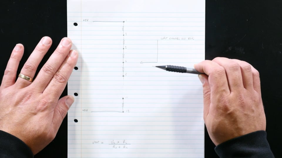
| 08:38 | Rightio so this is probably gonna be overhead shot just to make sure we've got everything in frame there so what I've drawn up here is simply a version of that rotary switch but on pen and paper. |
| 08:53 | Each one of these dots here represents one of the pins on the device there. |
| 09:01 | So we've got our 12 output pins there which gives us 11 gaps in between those 12 output pins. |
| 09:11 | And between each of those 12 pins we're going to solder a resistor. |
| 09:20 | And what this is going to do is we're then going to solder the input channel to the ECU to the 13th pin which was that single pin on the rotary switch there. |
| 09:30 | And then by moving the position that that ECU input channel enters into this chain, it's going to give us an adjustable resistor divider in essence. |
| 09:42 | So coming into our number one pin on the back of our switch, we're going to have a five volt sensor supply then we're going to go through our entire resistor chain all the way down to the number 12 pin on that rotary switch where we're going to make a connection to our sensor ground. |
| 10:00 | So that means our five volt is connected to our sensor ground but it's via all of these 11 resistors. |
| 10:08 | I like to use 1K ohm resistors for this as it makes the math a wee bit easier. |
| 10:14 | And limits the amount of current that comes down here as well so you've now got 11K ohm of resistance all the way between these two. |
| 10:23 | Then with that single pin that we can adjust the position of in this resistor divider we can get a variable output voltage going to the input channel on the ECU, we can set up a calibration in the ECU to reference those voltage levels that it's seeing to a particular parameter. |
| 10:44 | Now I have mentioned voltage divider there, that's a wee bit of math that we need to do. |
| 10:49 | So I do have the formula written down here, you can find it easily by googling, or I am actually going to show you a spreadsheet that I've put together as well. |
| 10:58 | That is going to be, make things much much simpler to get all the required voltage levels out of it. |
| 11:06 | But for working out a voltage divider we'll actually just quickly draw what a voltage divider is. |
| 11:12 | So a voltage divider is when you have two resistors in series like this. |
| 11:19 | With a voltage across them, in this instance it's going to be five volts as we're going to have our five volt sensor supply here and our sensor ground here. |
| 11:29 | Then at this point here you're going to have an output voltage which is going to be determined by the ratio of these two resistor values here. |
| 11:38 | So we're going to call this R upper for the upper resistor, we'll call this R lower for the lower resistor. |
| 11:45 | And then our voltage at the output here is simply going to be determined by our supply voltage times the value of our lower resistor divided by the sum of our upper resistor and our lower resistor. |
| 12:00 | So if we said these were both say 1K ohm resistors like I talked about, we would have five times our lower resistor which would give us, I'm actually going to get my calculator here because doing this in my head on the camera is going to end in disaster. |
| 12:19 | We would have five volts times our lower resistor value which would be five times 1000 giving us 5000, and then we would be dividing that by the sum of our two resistors there, which is going to be 1000 plus 1000 which would be 2000 so we can divide that by 2000. |
| 12:37 | Which is gonna give us an output voltage of 2.5 volts. |
| 12:40 | That was a pretty obvious result. |
| 12:42 | Because we had two equal value resistors here so it should be reasonably obvious that half that voltage would be dropped across either of those so we'd see half of our supply voltage at the output here. |
| 12:54 | If we instead say had 5K of resistance here and 1K of resistance down here, we would now have a bit of a different story. |
| 13:04 | We've got five volts times our lower resistor which is gonna be our 5000 again. |
| 13:10 | Divided by the sum of these two resistances. |
| 13:14 | So I think I said we were gonna have 5K resistance on the top and 1K on the bottom so that's gonna be 6000 all up so if we divide that by 6000, we would get an output voltage here now of 0.83 volts. |
| 13:29 | So as that upper resistance increases, it drops more voltage across it so that voltage we see at out output is lower. |
| 13:39 | So yeah sorry little bit of math there, it is particularly dry to go through, but it's reasonably important that you understand that concept that all we're building with our rotary position switch here is a variable resistor divider, one that we can change that upper and lower resistance to get a different output voltage. |
| 13:59 | So might just have to hang there for a second because I've just realised that I don't have this spreadsheet open, I'll just pull it up really quickly. |
| 14:10 | Yep here we go so if we pop over to my laptop now. |
| 14:12 | I do have a bit of a spreadsheet here to make the calculations a little bit easier. |
| 14:18 | So we'll just go through quickly what we've got here. |
| 14:21 | Ignore this in blue down here for the moment, we're gonna talk about that a wee bit later on, it's a way of hooking up one of these rotary switches to a temperature input channel as opposed to an analog input channel. |
| 14:34 | So for our analog input channel we've got our five volts into our pin one on that switch, we've got our zero volts into pin 12 and we are then just adjusting the point that is connected to the ECU input channel between those two points. |
| 14:52 | And we are adjusting the resistance across that bridge. |
| 14:58 | So you can see here as we move through those rotary positons the voltage that the ECU is seeing is actually decreasing the higher we go. |
| 15:08 | Right I'm just gonna pop back to my notes quickly. |
| 15:17 | There we go. |
| 15:18 | So hopefully that's reasonably clear as to how we're going to actually inplement one of these. |
| 15:24 | So we are going to be taking our resistors, 1K I like to use as I said as it keeps the math really easy and we're gonna be soldering them in a continuous chain along between each of these pins. |
| 15:38 | I've actually got one that I've done a little bit of work to here. |
| 15:41 | It's gonna show it quite nicely, hopefully. |
| 15:44 | You can see I've got my pins and they're just forming a resistor chain like we've got here on the paper. |
| 15:53 | So that is, so yeah, to hook one of those to your analog input channel, yes you're gonna have your five volt to that pin one, your resistor chain through all of those terminal positions, then with your zero volt on that last terminal position, pin 12, and then input channel to your ECU is then going to be connected to the input pin on that rotary position switch, that pin number 13. |
| 16:20 | So hopefully that's pretty clear as to the math that drives behind that. |
| 16:24 | And this is for the case that you're hooking it to an analog input channel, and you have a five volt supply, a ground and the actual sensor pin as well. |
| 16:34 | I did mention before we'll have a quick talk now about how you hook one of these switches to a temperature input channel and how that varies slightly from hooking it to an analog input channel. |
| 16:45 | We are gonna be having Q&A at the end of today's webinar. |
| 16:49 | It is gonna be quite a quick one today, but if you've got any questions about what we've gone through, or about to go through, start popping them in the chat now and we will, I'll answer those once I've talked about the next section which is hooking one of these rotary position switches to a temperature input channel. |
| 17:09 | Now quick talk about the difference between a temperature input channel on an ECU and an analog input channel on an ECU. |
| 17:15 | Essentially they are the same thing once you get inside the ECU. |
| 17:20 | The difference being that a temperature input channel has a dedicated pull up resistor inside the ECU. |
| 17:27 | So this pulls the signal input line up through some resistance value, quite often you can actually define it inside the ECU to the sensor supply voltage which is typically going to be five volts. |
| 17:42 | What that does is it then forms a resistor divider between that temperature output channel and the sensor ground level. |
| 17:51 | And by looking at the voltage seen on that sensor output channel, that is the amount of voltage that has been dropped over the pull up resistor, the ECU can determine the resistance of the sensor that's wired to that temperature input channel. |
| 18:08 | And the resistance is really what it's wanting to know as the temperature sensor will be calibrated for a resistance versus temperature curve, most commonly anyway. |
| 18:20 | We're essentially going to do exaclty the same thing as basicallly we've got a system here where we can give the ECU a varying amount of resistance. |
| 18:30 | So just pop over to that overhead camera here on the shot and have a quick talk about how this is actually set up. |
| 18:37 | So you can see here this section here would be inside the ECU. |
| 18:44 | This is your five volt sensor supply line on the printed circuit board of the ECU. |
| 18:50 | This is your ECU in temperature input channel and it'll be pulled up with a pull up resistor inside the ECU to that five volt line. |
| 18:59 | By then connecting that temperature channel to different points in our resistor chain on our rotary selection switch, we can vary the amount of resistance between that temperature input channel and ground. |
| 19:11 | The ECU can compare its known resistance here to its unknown resistance here and we can generate a calibration setup inside the ECU to get those various modes into the ECU going where they need to go. |
| 19:30 | That is the difference between a temperature input channel and an analog input channel on an ECU, it is just this internal pullup resistor. |
| 19:37 | If you've got an ECU where you can define the value of this pullup resistor, that is a really nice feature to have. |
| 19:45 | If we just pop back over to my laptop again quickly, the lower part of the spreadsheet here I've got set up for if our rotary positon switch was hooked to our temperature input channel here. |
| 20:03 | So I've got a column here that is the internal pull up resistor so I'll just set that to 1000 'cause that's a pretty common value and I'm still going to be having 1K ohm resistors in between my resistor bridge here. |
| 20:19 | So these are all the resistances that the ECU is going to see. |
| 20:24 | And what you can see here is the actual generated output voltage is not particularly linear in reference to our actual switch position here. |
| 20:37 | You can see our first switch position, our ECU is going to see a voltage of 4.58 volts. |
| 20:43 | For our next switch position our ECU is going to see a voltage of 4.55 volts. |
| 20:49 | So that's really not a big difference, you've only got 30 millivolts of difference there and it's quite possible that's going to be within a noise threshold or a filtering threshold and your ECU quite possibly is not going to pickup that change, or if it can pick up that change, it might be susceptible to noise, giving it errant changes on that line as well. |
| 21:09 | This is why having an ECU with a selectable pull up value can be really handy. |
| 21:16 | Another common pull up value that you're going to see is 3.3K ohm. |
| 21:21 | So if I change this to 3300, so 3300 ohms, you can see our voltages here are still not great but they're much better. |
| 21:32 | Between our first two settings here we've got 3.85 volts and 3.76 volts. |
| 21:37 | So we've got 90 millivolts there now so that is, it's definitely better, we're heading in the right direction, but probably still wouldn't be particulary comfortable with that. |
| 21:48 | What you end up finding is typically the around about the optimal pull up value is going to be around about half of the value, the overall value of your resistor chain. |
| 22:00 | So we've got a overall resistor value chain resistance there of 11K ohm. |
| 22:07 | So half of that is gonna be 5500. |
| 22:10 | If we put that in we've now got a span of voltages that's looking a wee bit better. |
| 22:15 | Its overall maximum voltage has lowered but the steps between each of these voltages has gotten a wee bit larger, particularly up here in this area. |
| 22:26 | It's always going to be quite large down here but it's this area we need to focus on. |
| 22:31 | So we've got 100 millivolts of difference here now and that should be enough to be reliably seen by your ECU and be pretty good. |
| 22:40 | You can play around with this, I am going to put a link to this up in the webinar section of our forum when we're done. |
| 22:47 | Changing these resistance values here is the other option if your internal pull up inside your resistor is fixed. |
| 22:55 | So if we were fixed to a 1K pull up there you could change the resistor values here. |
| 23:02 | You don't even need to keep them in even steps, you don't need to use 1K ohm resistors for every single part of your resistor chain, and changing the actual resistance value as you move in steps can help you smooth out this a lot as well. |
| 23:17 | You are going to be subject to the availability of the resistors there. |
| 23:23 | The different resistance values that are commonly available. |
| 23:28 | We'll just have a quick look at this resistor again that I've done a wee bit of work on, I haven't actually completed the entire chain around it as I'm not completely certain what we're gonna end up using this one for yet. |
| 23:40 | I suspect it's probably gonna end up on the steering wheel of the SRZ project. |
| 23:44 | So I don't know how many modes we're going to want so I haven't completed that chain yet. |
| 23:49 | But you can see we've got our number one position here in that chain to our number two, to our number three, to our number four, and so forth, and you would just continue all the way around or for as many positions as you're going to want to need. |
| 24:03 | Now I did mention the dreaded solder word, yes I have soldered these, it is the right way to make a connection to this style of pin. |
| 24:10 | However that does mean that we're going to need to be doing some strain relieving and we're going to need to be pretty careful about how we're doing that. |
| 24:18 | In this instance chances are I would probably make a wee fixture that I would fit this in, I would pot this entire area with our epoxy sealing compound, something like a ResinTech RT125 or a Hellermann V9500. |
| 24:34 | Then I would most likely boot that in a shrink moulded sealable boot. |
| 24:41 | I have got another rotary position switch here to show you, which this has basically been done to already. |
| 24:50 | So these are available from Motorsport Electronics here in New Zealand. |
| 24:54 | No we don't get a discount for mentioning them in the webinar. |
| 24:57 | They are just, he makes good products so I don't mind showing them. |
| 25:02 | So he will have done exaclty that and I suspect this is still a Grayhill series of switch. |
| 25:09 | But it is a much smaller one, it's probably got PCV contacts on the back and I suspect in here he's got a printed circuit board that has all the resistors mounted to it and then everything is potted and sealed into that. |
| 25:24 | Buying rotary switches that are set up like this can get reasonably expensive. |
| 25:30 | So that's why I really wanted to go through the process of actually building one yourself. |
| 25:35 | Even going through that process will just really help you understand how they work, so if you're doing any troubleshooting down the line you'll have a good idea of what you're actually looking for. |
| 25:43 | So this is gonna be a 10 position rotary switch and it's set up to be, they've set it up with our three wires here so we can wire that to our analog input channel or by omitting our five volt supply wire we can wire it to a temperature input channel but I would in this case be wanting to have an ECU that I could adjust that pull up value resistor on until I got those different stages into a nice range, particularly at that upper end there. |
| 26:12 | As I obviously can't get into this to change the resistor values on the back of our switch. |
| 26:18 | Right so that is in a nutshell how to hook up, in a nutshell, that's probably actually quite long winded. |
| 26:26 | That is how you hook up a rotary switch to your ECU and get those variable voltage levels into the ECU which you can then generate a calibration inside there to give you your different settings that you're going to want to be going for. |
| 26:39 | That process will be particular to your ECU. |
| 26:41 | We absolutely couldn't go through them here as there are just so many different ECU manufacturers but it should be well documented in the documentation for your ECU. |
| 26:52 | Or you could get in contact with the technical support line for your ECU manufacturer, they'll be able to help you out with that as well. |
| 27:00 | So hopefully that's been some good information, good short one today, as I said I've just seen this question coming up quite a few times in our forum and on some of the Facebook groups, I though it would be good to go through it in webinar form. |
| 27:14 | Hopefully given some good information there and you've got a good idea on how to set up one of these. |
| 27:18 | Maybe even a bit more information on resistor dividers and the difference between temperature input channel and analog voltage input channel. |
| 27:27 | So we'll pop over to the questions now and get into those. |
| 27:36 | Ben has asked can you use rotary pots with position detents as well? Yes absolutely you can. |
| 27:43 | You are still generating a variable resistance there. |
| 27:46 | In fact the setup for, sometimes you actually just want a rotary pot, you might want a completely smooth transition throughout your resistance range there, you might not be aiming for specific spots. |
| 27:57 | But if you've got position detents there, yes that is going to work. |
| 28:02 | I'd probably still be heading for an actual switch like this though. |
| 28:06 | As I suspect it's going to end up being slightly more reliable depending on the rotary pot that you've got. |
| 28:13 | Obviously another situation where you're using rotary pots a lot in motorsport is for say a gear positioning sensor on the back of that gear barrel. |
| 28:24 | And the system for setting those up into the ECU is actually exactly what you're talking about. |
| 28:32 | You've got specific detented positions for that gearshift barrel with a rotary pot on the back there so it's going to be in distinct locations, that rotary pot's going to then be also be in distinct positions so you're going to have voltage levels coming out that are going to be dependent on the distinct gear that you're in. |
| 28:51 | In that situation it's really critical that you are using a rotary pot actually as the ECU will start looking for the change in that voltage coming into the ECU. |
| 29:03 | If it's a good ECU it should be looking at the rate of change. |
| 29:06 | So it knows how fast that gear pot is moving, you can set up all your gear change cuts or acceleration blips around that as well. |
| 29:15 | I'm getting slightly off topic here but I love talking about it because I have had quite a bit of experience setting up gear change systems, paddle change systems on race cars. |
| 29:26 | If you're ever in the situation where you're setting one of those up, thousand hertz logging is an absolute must on that gear barrel position. |
| 29:32 | And you can actually see in quite a lot of detail really what's happening when your'e going for that gear change. |
| 29:39 | You can see if that gear barrel has tried to move, the dogs are still locked, and then they release and then it clicks into gear, you can see all of those wee bumps and flutters in that gear barrel position sensor output. |
| 29:52 | And you can tune around it, you can measure the length of all those sections and you can get the detail of that gear position cut down and you can get those gear shifts much nicer. |
| 30:03 | A couple of benefits there, few milliseconds difference, probably in the actual shift time. |
| 30:07 | But it does make things a wee bit nicer for the gearbox and you usually get a bit of a reliability increase there as well. |
| 30:16 | Selina Camaro 98 has asked does this work on an OEM ECU or is an aftermarket solution such as a Haltech required? Ask because race car still has factory Camaro ECU with a remap. |
| 30:27 | I would say the 99% answer to that is you are going to need an aftermarket ECU. |
| 30:33 | That being said, there are a lot of people that have done some pretty fancy things with reflashing OEM ECUs and if it's a 98 Camaro you've got, that's probably gonna be around the LS motor era. |
| 30:46 | Those ECUs have been pretty well decoded and there are a lot of different firmwares available for them that actually unlock a lot of functionality. |
| 30:55 | So there might be the facility now for that OEM ECU to reflash a different firmware into it that can take a rotary position switch. |
| 31:04 | I believe it would be a similar story for something like the Mitsubishi Evo range of ECUs and a lot of the Subarus from around about that same era and even the mid 2000s have been pretty well decoded and there are different firmwares available for them. |
| 31:20 | But 99% of the time no your OEM ECU is not going to have an available input to wire up any additional sensor into let alone a rotary position switch like we've got here, it is going to be for you aftermarket ECU. |
| 31:37 | Rightio that's the end of our questions there guys. |
| 31:40 | So thanks heaps for tuning in. |
| 31:43 | Really appreciate it, hopefully there was some good knowledge there. |
| 31:47 | Nice wee quick one to throw in the webinar archive that we can put some links up to next time I see the question come up about building a rotary position switch. |
| 31:55 | Thanks heaps guys, cheers for coming along and we will see you next week. |


