Sale ends todayGet 30% off any course (excluding packages)
Ends in --- --- ---
Hi! New to the forum and am trying to soak up as much information as I can. In the process of converting my FD into a time attack car and am trying to thoroughly plan out the airflow through/around the car. I'm still running the stock twins for now, so need to route two pipes for intake to the turbos. I'm installing a vmount with proper inlet/outlet ducting, so running two 2.5" pipes past all of that ducting to the front bumper will be near impossible. Most people terminate the intakes at the front of the engine bay, but then the filters are still sucking engine bay air rather than air from the front bumper. My plan is to have both of the intake pipes stacked on top of each other feeding into a 3d printed air box that would have a some custom shape to grab air from the front bumper and snake it to the box location in the engine bay.
Two questions:
1. Two 2.5" inlets would need a surface area on the front bumper inlet of ~10" for full flow. Is there any advantage to slowing down the air velocity/increasing the static pressure in the air box by having a smaller front bumper intake area and having an expansion to the air box?
2. Instead of two massive conical shaped intakes in the air box, it would save a lot of space to have a rectangular panel style air filter in the box mounted vertically in front of the intake pipes. I would think the air flow would be better with less filter obstructing it, but all aftermarket cold air intakes I see use the conical shaped filters at the end of the pipes, even in an air box, rather than a flat rectangular one. Curious on what the advantages/disadvantages are to having one panel air filter instead of two conically shaped filters?
Kellen
Hi Kellen, welcome 😃
The ideal situation is to take air from a cold (relative to the engine bay, anyway), clean and high-energy source. For us, that means somewhere on the front of the car.
As you mention, you do want to increase the static pressure by adding a gradual expansion along the duct. Theoretically, the expansion ratio should be in the order of 7 degrees max. Packaging is always a problem and very rarely do you have the room to expand cleanly and as gradually as you would like.
It also pays to keep all radii as large as possible, this is particularly tyre of the actual inlet. Sharp corners are no good here.
As far as the filter placement, a sensible arrangement I am most familiar with is an expanding duct that leads to a rectangular panel filter that sits quite close to the engine. However again, the practicalities of packaging will also play a big part in this. Below are some images of the kind of layout used on the current gen LMP2 cars to give you an idea.


Interesting, I'll have to rethink my intake filter panel placement and try to move it closer to the turbo inlets.
Looking at that LMP2 car, the final surface area of the intake duct after the expansion is orders of magnitude bigger than the surface area of the ITB's. Is there an ideal ratio between the intake's ducts final surface area to engine inlet surface area? On most modified cars I've seen, there will simply be an intake pipe with a conical filter on the end to the turbo(s)/itb's/plenum that is the same diameter as the inlet(s), meaning no expansion, even though a plenum kind of provides one.
In terms of ducting, minimizing the radii and expansion rate makes sense, but what should is the ideal duct inlet to outlet ratio? The LMP2 cars seems to have the initial intake size of about 1/3 to 1/4 the final size, which lines up with what you would do with a radiator/intercooler. Just wondering if that same logic applies.
As Tim said, what you're doing is changing from a velocity head, to a pressure head in the induction tract. This is primarily done by increasing the cross sectional area and reducing the velocity. You mentioned turbo-charger inlets - this is a different case, as the filter is placed around the inlet side and the focus is on feeding the air to the impellor as fast as practical to ensure it isn't being 'starved', I would suggest, where practical, a slowly tapering inlet expanding out from the turbo' inlet to the filtering assembly may be a good way to feed it. HOWEVER, not something I have experience of, so may be thinking with my bottom there.
The seven degree angle is a effective rule of thumb as it increases the area without losing the boundary layer - which can cause flow reducing turbulence. It's been quite a while, so I can't recall if that's per wall or total included angle. Sudden changes in cross-section are always a bad idea, as are tight radii.
One big reason for the filter medium being incorporated into the body of the plenums is to maximise the area of the filter medium. All filters will have a pressure drop across them, with some filter mediums being better flowing and others better filtering - it's a question of which is perceived to be more important - but the greater the area, the lower the restriction for any filter type. As an aside, many people don't bother using one, but almost any race car will be using a filter because the small lose of power compared to an open intake is easily offset by a big reduction in the power drop over the service life of the engine. As several series limit the number of engines that can be used in a year, or have heavy penalties for replacements engines, maintaining engine power is important - for the club/amateur racer, there can be a big financial benefit, too, and that's even without the risk of the engine swallowing a stone, or something, that can destroy it.
On that, well spotted, there are some horrendous "filter" setups which are badly designed, way too small for the airflow demand the power requires, and that use restrictive and/or poorly filtering mediums. HKS has a very popular filter that fits all three/four, IMO. They are frequently made to take their air feed from warmer areas, such as immediately behind radiators, behind the engine, or close to the exhaust.
I suspect you may be over-thinking things a little, take some time and consider the whole flow path from atmosphere to the valves, and what affect this may have on how the air is expected to act.
As you thought, the plenum sizing is quite important, as too small will be restrictive, but too big will mean increased drag. There is quite a lot on the interweb that goes into a lot more detail than I can - https://www.google.com/search?q=sizing+automotive+plenum+openings%3F&client=firefox-b-d&ei=NPKLYJviH5_G4-EPyIuOoAc&oq=sizing+automotive+plenum+openings%3F&gs_lcp=Cgdnd3Mtd2l6EAM6BwgAEEcQsAM6BAghEApQ0IMBWN-nAWD3rgFoAXACeACAAewBiAGOEpIBBTAuOS4zmAEAoAEBqgEHZ3dzLXdpesgBCMABAQ&sclient=gws-wiz&ved=0ahUKEwibzIfE9qXwAhUf4zgGHciFA3QQ4dUDCA0&uact=5
This was my thinking about intakes for turbocharged applications as well. To avoid starving the turbo, I want to get as much air there as fast as possible. With the total surface area of the turbo inlets totalling 10 inches^2, I would have a bumper inlet of say double that, so 20 inches^2. Air filter would be placed as close to the bumper inlet as packaging/convenience of maintenance will allow, and then the intake would taper down from 20" -> 10" as slow as possible. This would serve to intake a massive amount of air compared to the off the shelf intakes like the HKS you mentioned, which are just straight pipes with conical filters in the engine bay. I'd have to do some math on how much CFM is too much CFM for the turbos.
For a rotary engine like I am using, the plenum design Mazda came up with works very well so I dont see a need to iterate on that. Am mostly focused on the turbo intake design.
Okay so went and did a lot more research, there is a lot of theory on this. Here is my understanding, the goal with a turbocharger intake (and inlet side in general) is to have as low of a pressure drop as possible. This means the turbo doesn't have to work as hard to pressurize the air seen at the manifold. This has multiple effects:
- turbo spends more time in the higher efficiency islands
- turbo will flow more air without over-spinning
- turbo spins slower, reduces exhaust back-pressure, increases overall engine efficiency
- turbo runs cooler at lower pressures
- engine is less likely to knock (huge for a rotary)
- turbo life is extended
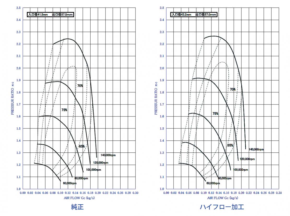
Having a large diameter pipe that is as short/straight as possible will result in the least amount of pressure drop. For a turbocharged application, the pipe needs to be able to flow the maximum CFM required by the turbo as well. Looking at the compressor map of the FD Stock twins, at sea level they will flow ~50 lbs/min at the choke line. Using a conversion factor of 14.471, that's 724 CFM of air needed at choke to feed the turbo while trying to minimize pressure drop.
Second thing that needs to be accounted for is velocity the air is moving through the pipe. Reading about air flow, these two posts 1, 2, point out that once the speed of the air hits a certain point, it starts to become turbulent and losses in efficiency start to expound. However, as post 2 points out, the velocity (Mach fraction) that was used to compute the pipe CFM does not take into account the laminar flow of air in a pipe (velocity is much greater before becoming turbulent) and does not take into account temperature i.e. pressure.
Without running some CFD, I'm not sure what the ideal intake taper should be from intake inlet to turbo inlet. If I have a 2.5" turbo inlet, should the pipe opening start at 3"/3.5"/4" etc. and how tapering will effect pressure drop since the air will be speeding up. Looks like I will be grabbing a beer and reading some white papers this weekend haha. Probably way overthinking/overkill but I find it interesting, let me know what you think.
I think you're going to end up teaching us ;-)
Check out Bernoulli's Theorum and Reynolds number, also - it's been around 25 years and I don't recall enough to be too much help to you, but they'll give you an understanding of the velocity-pressure relationship, and the affect of design on turbulence and overall flow.


