Sale ends todayGet 30% off any course (excluding packages)
Ends in --- --- ---
I've been looking at setting up another ecu recently and I have never really thought ahead with 5V supply on my car, it's just happened in the working mess it is.
Say you have 2 5V supplies from the ECU, A and B, and matching sensor grounds. Anyone have some strategies or ideas on what is a sound way to distribute it to the sensors?
For example, say you could put everything engine related on A and anything vehicle/driver related on B.
A could have TPS, MAP, Oil pressure, Coolant pressure, Fuel pressure
B could have Brake Pressure (front and rear), Steering angle,
Or is better to have some of the critical sensors on separate supplies? I assume there are many ways to do this, each with their on merit.
Given the opportunity, I put everything critical (and only the critical sensors) on one power supply. Usually this is just Cam/Crank and MAP and/or TPS. Those have critical changing values and the engine can't really run with defaults in the case of a sensor / power supply failure. The other sensors you mention, temps, pressures can all have reasonable defaults allowing the engine to run, but perhaps not a peak performance.
I follow a similar strategy to David, I try and put all the engine critical sensors on one power supply, and the less critical items on the other.
A related situation I encountered was wiring in some Izze Racing tyre temp sensors, which require a 5v supply, but communicate over CAN. Their current draw was relatively high, and by the time you power four of them from the sensor supply circuit of the ECU, you're almost up to half and amp of draw, which is pretty high for a sensor supply. Izze came to the party though and supplied an external 12v -> 5v regulator in a nice motorsport applicable package.
Depending on how many 5v supplies you have, it can be nice to separate digital signal sensors from analogue signal sensors, as the digital switching can introduce noise on the sensor supply line.
Ok, thanks for the replies guys. Using the existing loom, so I'll have to check where the crank and cam signals get power, it's not obvious on the information I have.
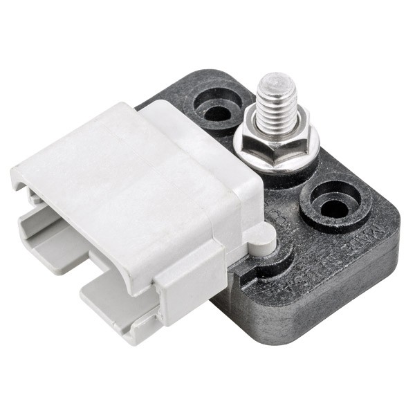
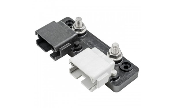
Another random thought on the this topic - splicing the supply voltage to multiple sensors - do you guys find it best to run a bus, like the connectors below, or is it general practice to splice them into the actual loom? From all the actual motorsport stuff I have seen, there never appears to be any bus used, but it does look like a convenient way of doing it.
Hi Shane
Nice terminal block with connector , could you share the brand or a web to look for, very useful ...
Also keen for a link to those bus connectors, very interesting!
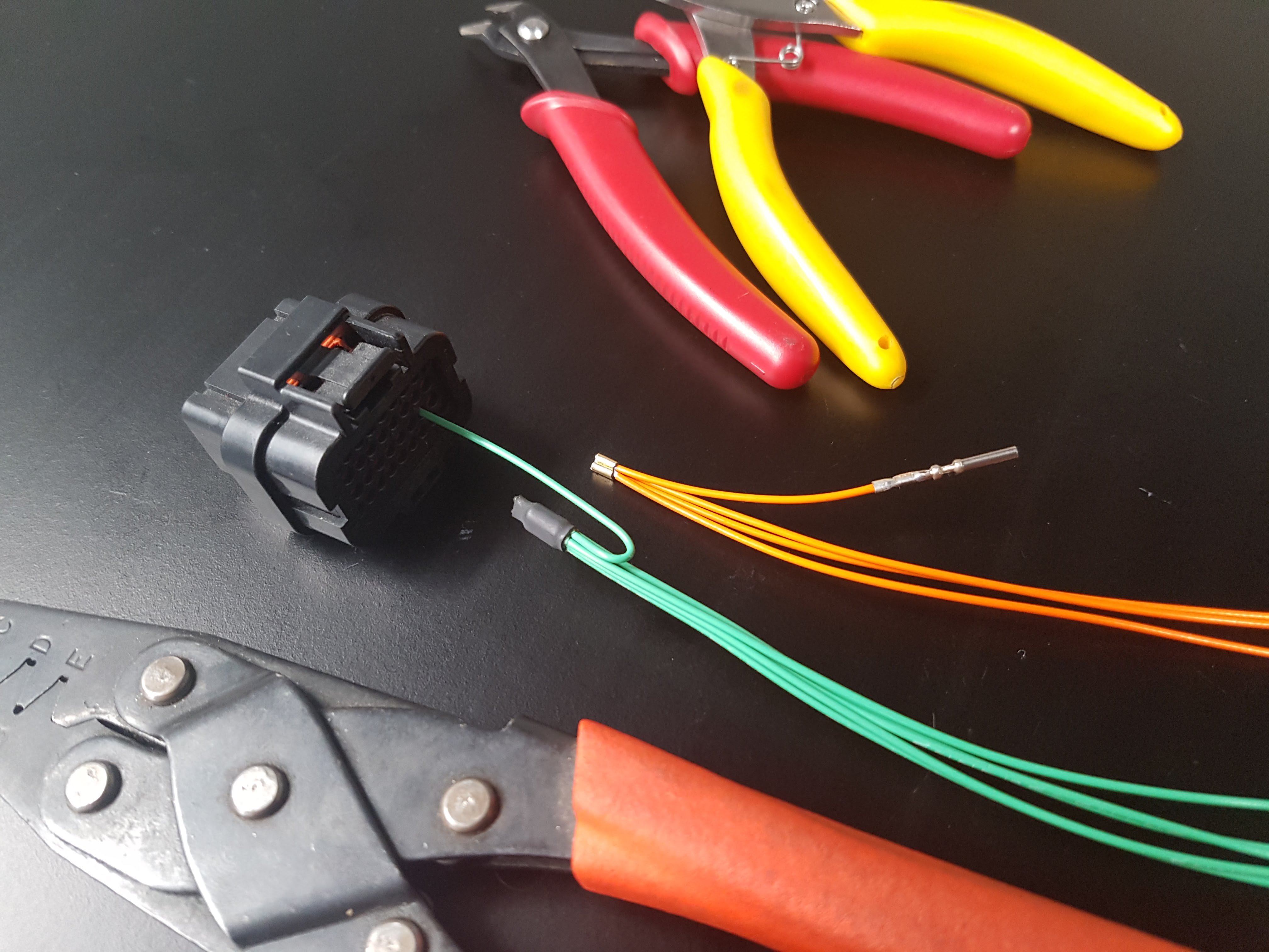
To answer your question though, I usually splice out a single 5V supply wire right behind the ECU connector to the number I need. This picture should give you an idea of what I mean:
Sleuthed out those bus connectors, cool shit!
https://www.ionnic.com/electrical/connectors/deutsch/bussed-connectors.html?show_item=1009
Thanks for the link Zac !
Yeah, sorry for the late reply but we get them from Ionnic. Be nice if Deutsche did them for DTM connectors, but using the DT isn't too bad. Seem like they'll come in handy.
Zac, thanks for the picture, very neat way to do the splice.
I am having an issue with all my 5v sensors that is concerning and I think this might solve it. Let me know what you guys think.
Your problem doesnt seem to be related to the original topic of this thread which was how to distribute multiple 5V supplies when you have an ecu that provides more than one isolated 5V pin.
However, your log shows both positive and negative spikes on all the 5V sensors as well as the RPM trace, with only some of the spikes being aligned so its hard to imagine what would cause that. Possibly you have a bad ground on some high powered device and you consequently have some stray current passing through the sensor ground?
It is however very odd that fuel pressure shows 3X more spikes than the oil pressure which shows 3X more spikes than the MAP sensor. It could potentially be an internal hardware problem? The fewer spikes in MAP could possibly be explained by heavily filtering or synchronous sampling I guess but I would expect oil and fuel press to show the exact same problem if they were connected to a common supply/ground.
TPS shows no spikes at all. So what is different about the TPS?
Is the crank sensor powered by 5V - or is the ground the only common connection between all these?
Hey! Thanks for the reply!
I tried checking my grounds this morning and tighted up some loose power grounds. the problem seemed to go away for about a minute then right after I was filled with joy I was quickly shot down by the ecumasters gods and the problem reoccurred.
the tps has a common spliced sensor ground with all of those erratic sensors, which makes me think it’s not the sensor ground I could be wrong though.
my crank sensor is not powered by 5v and the ground is the only common connection.
do you think a bad voltage regulator in the ecu could cause it?
edit:
ecumasters got back to me and said:” It appears analog #2 and #3could be affected by an intermittent sensor ground connection to the sensor. TPS voltage does not seem affected.
Without the project file, we can't see if this is the internal MAP sensor.
I would also draw your attention to the jagged RPM and the "CAM sync trigger tooth" that should be solid at "24" and not fluctuating. This is normally a sign of the secondary trigger edge needing to change. “
the plot thickens, this discussion might be better suited for its own thread
Well from what you have said the sensor ground is the only common factor, so that would be what I investigate first. It could still be an internal problem. Im not convinced about their explanation of the cause of the cam sync tooth fluctuation being due to the edge setting. Since it occurs at the same time you have spikes on your sensor traces I would say it is more likely there also is a spike on the cam or crank sensor waveforms at the same time - causing it to see an extra "tooth" and losing count.
A quick test would be to back probe the ground on one of the sensors that is showing obvious issues and connect it direct to the engine block with a small jumper lead. Then you know that sensor has a solid continuous ground (and any sensor that is connected to the same ground provided the wire is not broken). If the spikes disappear on that sensor with a backup ground connected then you will know it is a grounding issue.


