Sale ends todayGet 30% off any course (excluding packages)
Ends in --- --- ---
I am continuing to fine-tune my build and trying to learn more about Transport Delay. I use a Performance Electronics 8400 ECU which has a simple entry for transport delay based on the number of revolutions of the crankshaft. Their manual says it is determined by volume of the cylinder and distance between the valve and the sensor. Simple calculation however they end the sentence with the comment "A typical setting is '10'".
On most short header, higher displacement engines, this number calculates between 3 to 6. The manufacturer is having a hard time explaining why the '10' reference since the gentlemen who developed this part of the program is no longer with the company.
I have studied many of the patents surrounding this part of ECU tuning and see a lot of other factors enter into these calculations. Electrical response times, exhaust velocity, cylinder balance, etc.
As I work to understand this further, I am curious what other ECU's may use a similar type setting. I would like to read their documentation on how they say to set this function.
Can anyone offer if their ECU has this feature or is it hard-coded and is there documentation on how to set it.
Thanks,
Paul
Mount the sensor directly after the header where all cylinder tubing meet and you will not have to worry about transport delay.
DynoDom
I disagree. From the exhaust valve to the collector, where the O2 sensor is mounted is approximately 40" There is a transport delay
Is this LAMBDA Transport Delay, the period between a change being made and the response from the sender?
If so, the suggestion here may help?
Gord, yes, this setting is part of the Closed Loop Lambda/AFR Control, figures into the Short Term Fuel event.
I am hoping to find other brand ECU's that have this configured in a similar way that I can study how they recommend it be determined.
A suggested method is to change the fueling dramatically and by using the log data, then determining how many revolutions the engine makes before the change is noted. However, the graphing of my Lambda changes is so erratic, it is impossible to do this with any semblance of accuracy. I am hoping by reading the other brands documentation, I can learn a little more about this.
Most of the stuff that a Google search finds is based on tuning/modifying the factory ECU settings. (Mustangs and LS Motors) where it has been established by the factory and they are then modifying it due to header changes. I find very little reference on how to determine it from scratch, which would apply to a stand alone ECU
Your post above says ". . .the suggestion here may help?" but there isn't a link to anything
So I see, sorry - must be old age kicking in - it was similar to what I think you say you're already trying, logging the change and the delay at the lambda and charting it to figure out the corrections required.
https://help.emtronaustralia.com.au/emtune/Newtopic466.html
https://help.emtronaustralia.com.au/emtune/Newtopic276.html
I may be mis-remembering, but I understand foulled and/or old lambdas can also add a delay?
BTW, did you get the fuel puddling on the throttle blades, at idle, sorted out for the FE monster?
Paul,
Transport delay will vary greatly as exhaust mass flow changes, so a table without that involved, or anything you could use to approximate it and reflect how your setup's transport delay changes with exhaust mass flow, seems inherently flawed.
A table with a single unknown value, seems it would not allow you to represent the range of engine operation.
As usual, I admire your desire to optimize the system, but no matter how much data you gather, if you can only ultimately enter this single mystery value, it's not going to be optimal across the range of engine behavior. Your best bet may be getting it to work decent at idle/light throttle cruise and then hoping at high flow things are happening quickly enough that the impact of incorrect delay comp is small.
On top of that, if you have closed loop trim PID settings you can alter gains or other settings on based on RPM, throttle, etc., you may be able to account for the portion of transport delay not otherwise accounted for, in this way.
Gord,
that does help. Interesting, they generate the change point by changing the Lambda target rather than the fuel load. Guess there's more than one way to do things. Hope I can find additional manufacturers' comments or documentation.
I have been able to make my fuel puddling better. Figured out how to use the Decel Fuel Cut which has really helped. It will never be 100% resolved due to the design of the hardware, but it is much better.
FWIW I use the lambda target change method on other ECUs. It's easily viewed in the log relative to when the lambda change is observed.
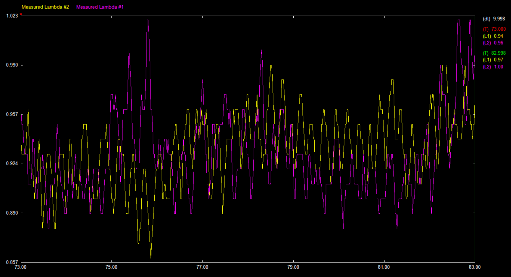
I looked at the links Gord sent and I am envious. The Lambda lines are so nice and smooth. This picture is of my log file charting Lambda over 10 seconds.
It would be much simpler if my data line were a touch smoother. Don't know how to make it so.
Have a think on my comment in that thread - I think it's the best solution and no-where near as 'strange' as it may initially appear.
Paul are your lambda readings that erratic with CL trimming disabled?
Mike
Disabling CL has no impact. The images of the traces in my upload were made while Closed Loop was turned off
Thanks Paul. The amplitude of the oscillations in your lambda traces is quite far beyond what’s typical of stable combustion.
From what I’m seeing, CL would likely not respond in an ideal manner simply because of the erratic lambda readings.
Does lambda stabilize if you target a richer mixture?
Mike
I've used these systems for 8 years. No changes will stabilize the Lambda trace. Systems have used two different external O2 conditioners, one proprietary, one by Daytona Sensors. Both provide a 0-5v signal which the ECU uses. Both use the Bosch conditioner and both have equally eratic traces.
It is complicated by running the systems with Borla ITB's so each cylinders air/fuel supply is not easily balanced.
In spite of the data readings, the car(s) run pretty good. I am probably chasing the last 5% but this one loose end keeps haunting me. I probably should be happy with what I have and how well it does. But this transport delay thing seems to be 'magical crystal dust'. I can't understand why there isn't more data/history/background on it.
I thought I had it solved earlier this year but as I resolve other issues to fine-tune the vehicles, it keeps popping its head up. very frustrating, not that I can't solve it but that I can't find any documentation on it.
Thanks for your help
Paul
Paul,
Without consistent lambda data to work from there will be very large error in in any testing for transport delay, and right now the data is indicating I would hold off on transport delay work until more significant areas of improvement are complete.
While some cylinder to cylinder variance is common, based on your lambda readings either your per cylinder variance is rather extreme, or the engine is misfiring, or both. I feel like you're hunting for the final 0.01% before a 10% or larger sized concern has been resolved so I'm suggesting that focusing elsewhere for now will likely provide you not only with more benefit, but hopefully get you to a point where you'll have better data to continue your transport delay project with.
Because lambda data is not collected at high enough speed and is from a collective location, we don't have data needed to fully characterize what's happening. What you're seeing in the lambda trace that looks a bit like an oscillation due to how the logger presents it, could be far more random. Individual cylinder lambda would give you a better idea whether you have large variances between cylinders or not, allow you to better account for that, and help you work towards more meaningful improvements in engine operation. With ITBs cylinder to cylinder variance at lowish throttle angles is often more extreme. You can set throttle base angles with a meter, but that doesn't ensure even AFR across them.
In the meantime if you haven't already exhausted injection angle testing, I'd see if that can make lambda traces more stable.
Mike, I am not on a dyno but using the seat of my pants to judge performance. The engine is 468ci with the ITB's and a mild camshaft.
1) Car pulls hard in all gears without issue, other than not enough traction
2) Cruising, I am getting 17mpg at 2200rpm
3) Car idles fine at 850rpm
4) no real issues other than trying to fine-tune the transport delay/lambda data trace coarseness.
I honestly believe it is at 90%+ right now and don't know what other parameters could be changed to make it smoother. I just haven't been able to gain the confidence that this last thing is correct, mainly due to lack of understanding. It may be perfect and I don't know it.
Can you comment more about the injection angle testing. Are you referring to the fuel angle? My current setting is 270degrees @ 800rpm and goes up to 470 @ 4000rpm (Injector Close BTDC)
Paul,
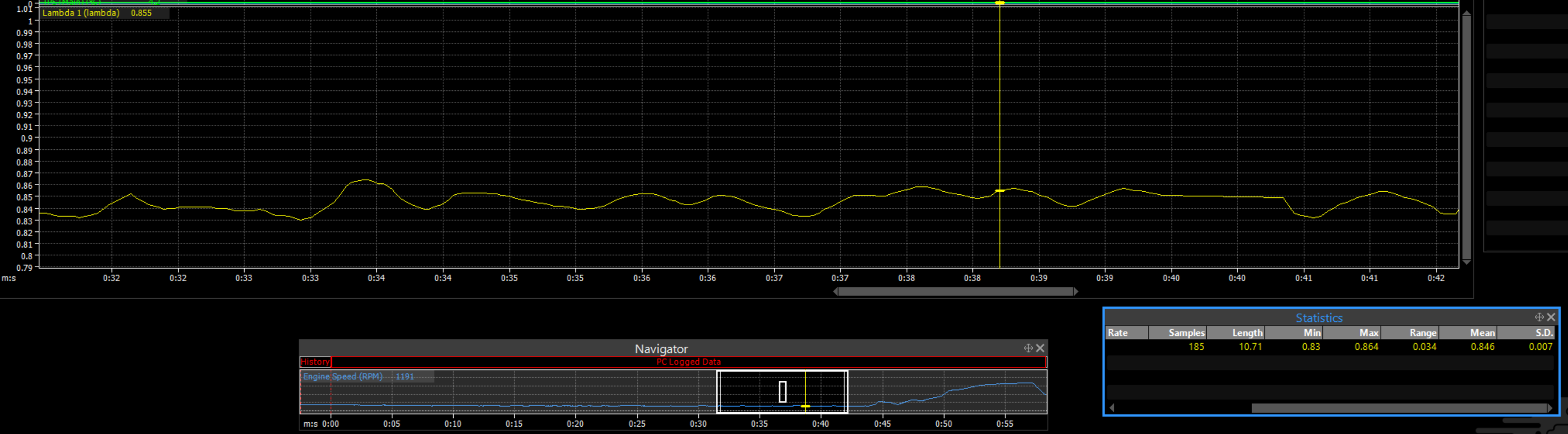
I'm hoping providing a reference trace will help put things in perspective. The data I've provided is logged at 50 Hz so it's more likely to include actual max and min values. I'm happy to continue discussion of transport delay, but I really feel I'd be remiss if I didn't give pointing out the abnormal combustion you have one more try. It indicates an area where there's massive room for improvement, and in the order of operations this should be sorted before transport delay. It will also allow you to gather meaningful data for things like transport delay tuning.
This is your screenshot of 10 seconds, taken at lower frequency so peaks and troughs are more likely lost. Variance over that short duration appears to be about 0.14 lambda, but true variance is likely higher.
I've attached a trace from a wild engine purpose built for drag racing with no streetability in mind. It has heavy porting, oversized valves, very aggressive cams and 2600cc injectors, which have not been per cylinder tuned to smooth it out at this time. I've selected a portion of log including some light misfiring at idle which caused max variance of 0.034 lambda. This is still about 1/4-1/5 the variance you have. Variance on a typical street engine is half this or less, making the trace look much like a line.
The very large and rapid variation in lambda you have in your log taken from collected exhaust gasses from an engine bank, typically comes from a sequence of combustion events which differ from each other very greatly. As I've mentioned some common causes are per cycle variation in individual cylinders (which may be injection timing related), variation in air or fuel or both from cylinder to cylinder, or misfiring from another cause.
On the chance much of the erratic combustion is related to injection timing combined with injector placement and ITBs, I was suggesting testing various start or end of injection timing values at idle to see if you can find a setting which stabilizes combustion and results in a more stable lambda trace.
If that does not help, at least it's a step towards narrowing things down. This assumes you're using sequential fuel injection so you have that level of control. If injectors are batch firing then that is likely a big part of the cause.
I think your exhaust system layout hurts your ability to gather good data. Are there slip joints upstream of the O2 sensor? Is the Engine side of the joint the inside or outside tube (or do you have double-walled joints)? Next, what is the diameter of the pipe downstream of the O2 sensor, and how far away is the exhaust tip? At what RPM is your Lambda trace captured. The lower the RPM, the more the air pulses and leaks will be reflected in the O2 readings.
Mike - appreciate that and I hear what you're saying. The confusing part is talking to the manufacturer of the ECU and looking at data from other engines, it seems the trace always displays this erratic response. Trying to get to their one knowledgeable guy to discuss this.
David - My exhaust system is a slip joint design, the joint upstream of the O2 sensor. The engine side of the joint is the inner pipe on the joint. I have meticulously worked to seal the joint and think it is so, but don't know how to verify that. After the initial installation, I then went in by hand and packed any possible openings to seal the joint. Again, I think it is but open to any ideas on how to verify a leak. Presently, I look for any carbon soot or buildup from a leak against the orange sealant. I have found a couple and packed them but nothing recent.
Below the O2 sensor is a 3" pipe and about 30" to the outlet. I've tried capturing traces at idle (850) and at 2500rpm with similar results. I am aware of the reversion problem when using side-pipes. On a similar project, I tried attaching exhaust hose sealed to the outlet to lengthen the distance from the sensor to daylight. I didn't find any difference, with or without the hose. Could O2 be getting up to the sensor? it is possible but I doubt it.
Hope I'm not wearing you guys out. There are few resources available out there to learn more about this. You can tell me to sit down if you want.
Thanks
Paul
If it's a simple slip joint, and you think there may be a problem, you can buy double slip joints, or sleeves. Usually they're sold as a 2 or 3 piece assembly, but a much cheaper option would be to cut some short sections, maybe 1/4"long, of the next size up exhaust tubing as alignment sleeves/filler, and some longer 1 - 1 1/2" lengths, two sizes up, for the double slip outers.
This might make the intent clearer -

For a quick test, you can wrap seal the joint with aluminium tape!
Paul, we want to help you see this through. You're not wearing us out. We're here to help each other!
Guys,
I think I might be onto something. Switched from the proprietary log viewer to MegaLogViewer HD. I can smooth the Lambda lines considerably. It may be the viewer was presenting raw data without any smoothing. I can duplicate the wild swings or I can smooth it to almost a flat line.
Curious, when using MegaLogViewer, what smoothing do you apply to a lambda line? With your input and experience, applying the smoothing that you suggest, I can then see is the issue the car or the log viewing software.
Paul
ps: is there any good training sites for MegaLogViewer? I've viewed the few webinars that are presented and picked up a few tips there, but no explicit sites on how to. Any suggestions on preferred settings or tips on the histogram feature
Paul,
There's a Facebook group called "MLVHD" that show some great features of the software. You can also check Andy Whittle Youtube page, he has some videos about Megalog viewer. It might be some more advanced features, but maybe you'll find something that suits your need.


