Sale ends todayGet 30% off any course (excluding packages)
Ends in --- --- ---
Discussion and questions related to the course Motorsport Wheel Alignment Fundamentals
Wondering what the main considerations are when setting up the ideal ride height for the car? A bit of background, previously I was running a set of Tein Super Street coilovers in my car - the only adjustment they had was the lower spring perch and I just set that mainly based on looks to be honest - the car was a road car primarily.
Fast forward to now and the car is now a dedicated time attack car. I'm going through the process of fitting different uprights to the front of it. I've already finished the work for the lower ball joints, and I've purchased new coilovers for the car. These are still designed for the original uprights however, so I had to fabricate new lower mounts for the struts (basically cut off the exiting tabs and weld on my own to suit the new uprights). I used a jig set up to come up with a method of ensuring that the height of the lower tube stayed the same relative to the wheel, so my height adjustment should be the same as it would have been with the original uprights. The offset between the hub and the strut mount on the two uprights was different however, as was the angle of the two strut mounting holes on the uprights, so I had to do a little bit of math when it came to deciding on the angle of these holes relative to vertical on these new tabs to ensure I had a good amount of camber adjustability. But I digress.
I understand the logic of adjusting ride height using the spring perch and not the lower mount, which is fine, and I know in the course that Andre recommended to have 2/3rds of the travel for bump and the other 3rd for droop, which I can adjust with the bottom mount. However I'm not sure how to come up with the correct static ride height?
Is this mainly going to be based on the position of my lower control arm to maintain a decent roll centre? I did add some roll centre correction into my design of the lower ball joint (as well as more caster). I don't have full diagrams made of the geometry, but I was basically going to try and target these arms being on a slight decline towards the outside of the car.
Thanks, great course content thus far.
The "correct" ride height is going to depend on 'most everything else, and might best be considered another tuning tool - remember, it will also affect the roll centre, CoG height, roll axis, caster, etc.
From what you say, I assume it's a strut type front suspension, the lower links forming a triangulated locating "wishbone", and the lateral viewed angle will affect the anti-dive characteristics of the vehicle - it sounds like you're adding compression under braking forces.
Not something I can advise on, specifically, but if you can provide more information on the vehicle there are some very smart chaps here who can give initial suggestions to work from.
Thanks for the reply Gord. The car is a Celica GT-Four (ST185). I have a post up also in the Build Threads section.
The front uprights are from a Prius (XW30). I'm using custom lower ball joint adapters with some added caster. I've used a GM style ball joint, so reamed the taper to suit. These are roll centre adjustable by using different thickness spacers on the king pin, but I'm limited to how much lower I can move the ball joint due to brake rotor clearance.

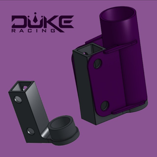
Here are the uprights just taped into position - I've redesigned the plates which will be welded to the strut tubes a few times to get the camber adjustment I want.

Basically I just used a jack to position the middle of the hub at ride height and adjusted the angle of the holes of the plates to get the camber to what I wanted, then drew them up in CAD, designed a jig as well which gets 3d printed and so all you need to do is sit the tube onto the jig, bolt the plates onto the jib and tack them on for welding.
This has been pretty straight forward so far, but I guess just trying to work out how to work out what my ideal ride height should be...
Also I have a lot more wheel to strut clearance with this setup, so I'm planning on fitting bigger rubber with different offset wheels to push them further inward. So I guess some info in what to look for for scrub radius, what works, what is excessive etc would be handy...
Thanks :)
Hi Nick,
Good post! The "right" ride height is going to depend a lot on the style of car, its intended purpose etc. I'll give you my thoughts and let's see where it leads.
Is your car primarily going to be making its grip mechanically or aerodynamically? To put a finer point on it - how much of that aero is going to be coming from the floor. If you're building something with a lot of downforce coming from the floor (I bring this up first as this is the direction a lot of time attack cars take), then that's what you should be building your car around the floor. That means your target ride height, max pitch and roll angles will be defined for you.
If however, the car is more mechanically biased then it's a bit more traditional. Very early in my career, a wise man told me that you build the car around the tyre and I've always found that to be sound advice. It depends a bit on how far you're prepared to go with remounting/making new suspension, but based on where you are at the moment, it sounds like you're going for it.
So what does that mean? For one, it means you need to select your tyre size before you go any further. Once you have that, this defines your fully compressed suspension position. This will be limited either by the tyres touching the inner guards (especially if your inner guards are stock and your tyres are wide) or the chassis getting too close to the ground.
If you have already selected your dampers, then that kind of locks in the rest for you. The 2/3 to 1/3 rule you mentioned essentially defines the damper stroke position you need at static ride height. This now enforces your ride height for you: your damper stroke position + the available suspension travel at each end of the car in compression + how low you are prepared to run the chassis to the ground at full compression/how close the tyres get to the inner guards gives you everything you need.
All this really goes on the assumption you're trying to get the CoG height as low as possible, with the caveat that you'll be correcting the kinematics as you go. Some of this comes down to the practicalities of how much stuff you're willing to move/how much time you'll spend with an angle grinder and welder! Things like space and angles for driveshafts etc will come into it, potentially relocating steering rack etc.
If all that's a bit much for you, you've really just got to come up with what you're limiting factors are - this could be something like driveshaft clearance before it hits the chassis for example, and maybe you're not prepared to modify the chassis for clearance. Whatever the factor is, treat this as your minimum, then let the 1/3 to 2/3 damper stroke rule guide you from there.
Out of interest, what's the advantage to the Pirus uprights? It looks like they are Aluminium, but I've not heard of people using these before.
Tim
Hi Tim,
I'm building the car to Clubsprint rules, so somewhat limited by the rules in what I can do. Basically I competed in the car as mostly standard back in 2019 in local Time Attack, then the block cracked at the end of the year and I decided to strip the car completely and focus on re-building it from scratch, with the mentality of making it easy to work on and reliable, so set out improving the problem areas as I went. So it has a pedal box now, steering column from a Toyota 86, surge tank, I'm redoing the wiring using a PDM etc (yes, I'm also a member of HPA :) ). So not intending for it to be a record breaker, it's for my own enjoyment, but obviously want it to handle as well as it can - as long as getting it there is within my somewhat limited skillset!
One of the main issues I had with the car was the front wheel bearings. The factory uprights have tiny little bearings and they don't cope well with track abuse - not only do they wear quickly, but it made pad knockback quite excessive. Then to change them it's quite involved (press out) and you also need to replace the hub, which is becoming difficult to buy. The Prius upright has a bolt in style bearing, so it's easier to change, plus it's actually larger and stronger so hoping I don't need to change them as often and that the added strenth will reduce the flex and pad knockback. That's the theory.. With Clubsprint rules, I'm allowed to change the upright, but had to stay with the same manufacturer. The Prius met the brief as it was the same PCD so I could use my exisitng 2 piece rotors I had from my brake kit and the splines matched up. I just had to remake the brake caliper adapters. It seems I've also gained a fair bit of clearance from the wheel to the strut too, which will help.
Sorry for the long answer so far, but it gives you a bit of an idea in to the use - most of the grip will be mechanical - I have a front splitter on it and intending on putting a simple bootlid wing on it

One of the rules of clubsprint is not moving pickup points for the suspension. I'm intending on going with a slighty wider tire than I'm running now - max width for the class is 265, would be good to take full advantage of that, even if I have to cut the guards and use over fenders, but I was hoping to avoid that. So might end up being 245s or maybe 255s. The new uprights have given me extra track width so I should be able to move some tire inwards using different offset wider wheels.
But I think I understand the basics of your message above - put my wheels on, determine my suspension travel limitations consideirng the width of tire I want to go to and make sure my suspension travel is clear.
Thank you - you'll more than likely see more questions popping up from me in the near future!
Wise man, indeed, Tim. I've used the expression "drive round the front tyres"for years - by that I mean maximising the grip offered in braking, turn in, and through the corner - back in thday most club stuff was on metal (gravel) and most would drive on the rear tyres - 'chucking' the car in and using a lot of wheelspin induced oversteer while actually carrying less speed through the corner - get the balance right and...
Nick, some nice work there, I especially like your using the 3D printed fixture - there is a lot of potential for the process as a manufacturing tool for the home builder as you illustrated.
I also have a dislike of excessive offset, and like the idea of reducing it as it reduces the arc of the tyre (which can be a problem with wheel tub clearances on lock), and positive scrub which loads up the bearings and steering. However, it does reduce the clearance to the 'wishbone' formed by the lower links and possible the steering tie rods. It may also reduce the width across the front tyres and it's normal to try and use as much as is legal - might be possible to run wider tyres, though, too - so a careful review of the entire front end, and it's possibilities, may be in order.
I would make one little clarification point, a "king pin" refers to a specific part of a beam axle, and led to the term 'king pin inclination' being used for the angle the virtual 'king pin' would have operated through. With a strut it's the angle of the top pivot point and the lower balljoint, which you refer to as the 'king pin'- just call it the bottom mount, ball joint or pivot, as it's easier to follow.
Ah, right. I actually thought the pin that went through the balljoint was the kingpin. So with a strut system, is the kingpin position / inclination actually a virtual measurement based on a number of other measurements?
You're welcome Nick. In the situation you describe, the limiting factor is often getting enough bump travel from a front strut. You often end up in a situation where you can run the car quite low (again assuming you can correct the kinematics properly) but the travel is limited by the height/travel of the strut. One option is to lift the top of the strut tower, the limiting factor is usually not wanting the struts to protrude through the bonnet, but in your case, it sounds like rules may restrict this as well?
In your case, having an adjustable lower mount can help you a lot here to get you in the ride height window, but also the overall susp travel window. Keep us updated, looks like you're doing some really good work, you're the kind of person RaceCraft was designed for. Questions welcome at any time!
Tim
Ah, Nick, I see where some confusion may be coming in.
This should be of help,https://en.wikipedia.org/wiki/Kingpin_(automotive_part) and there are also further illustrations available on-line https://www.google.com/search?sa=X&source=univ&tbm=isch&q=vehicle+kingpin&client=firefox-b-d&ved=2ahUKEwjp1Pnx_NHwAhWj4jgGHUX9B8sQ7Al6BAgHEF8&biw=2144&bih=1150
In short, it's the axis the wheel assemble pivots around as the vehicle is steered, from the front it is referred to as the KPI, and from the side as the 'caster angle'. It's different from the camber angle, but as the stub axle/carrier is a single piece any change in one will have a direct affect on the other.
In vehicles that don't use a beam, the KPI is really a virtual angle and is projected through the top and bottom points where wheel carrier assembly is rotating through, with common wishbone type suspension it is through the outer ball joints, and with strut type suspension it is through the top mount and bottom ball joint where the track control link/wishbone is attached to the strut. With multi-link suspensions it is much more complicated as it may move around as the steering and/or suspension operates.
Don't forget, as you're moving the locating points around for the roll centre adjustments, you will almost certainly need to check and make changes to the steering linkages, possible even movingthe rackand/or the outer, stub axle, tie rod's joint position to counter the roll/bump steer that may be introduced.
Hi again guys. From watching the wheel alignment video I see when Andre moves the wheel into full bump it recesses into the guard. Obviously this is fine when the wheels are pointing straight ahead, but will contact when turning. So how do you know how far is too far?
I've now got my suspension tubes done so I'm able to test fit the upright with a wheel on it and jack it up with no spring installed. I worked out that my suspension travel is 80mm. At full bump at the ride height I'm going with, the wheel clears the fender however if you turn, it contacts lightly. Appreciate I'm probably going to be coming up with a solution for more clearance anyway but just curious if this is a normal situation.
There are some instances where stock wheel and tyre sizes will sometimes rub and when changing tyre width, diameter, offset, suspension travel, etc, it is common to run into interference with the wheel's outer and/or inner acrches, the inner body/chassis, and/or suspension/steering components. Some light contact, if at extremes, may be lived with, but there can be a big problem if there are sharp edges that can cut the tyre and/or be 'grabbed' and bent out of shape.
You're doing about as much as you can, checking the clearances with the springs removed and you will need to add a little for suspension deflection, especially if you're still using bushes, for braking and steering loads.
Oh, and don't forget to check for potential steering and/or suspension binding, as that can lead to breakages, which is never a fun thing to happen.
Hi Nick,
In an ideal situation, you should be able to use all the steering angle with the car at its intended ride height. This will allow you to manoeuvre the car around the pits without damaging anything. As Gord said, some light contact for the tyre on an inner guard you can probably live with, but it has to be very minor. In my experience, most of the time when you have a low car, with large and wide tyres you usually end up restricting the available steering angle to prevent rubbing with some rack stops.
The only time you'll be anywhere close to full lock is in the pits. For conventional circuit racing, when you're on track you use surprisingly little steering angle. This tends to make checking for interference with the suspension at full bump and some steering angle less relevant as this isn't a normal combination. You have to be doing something pretty severe with the car to have the suspension fully compressed with a significant steering angle!
A sensible starting point for figuring out how much steering angle and compression you need to allow for clearance with is to take the tightest corner on the track's you're likely to go to, along with the expected amount of suspension compression you'll have mid-corner on the outside front tyre. This is something you might have from previous data if you're logging suspension position. If not, you can do some rough hand calcs based on the lateral acceleration you expect to estimate it. If neither of those work for you, you'll just have to guess!
As for the amount of steering lock, if you haven't got logged data of steering angle you can refer back to, then maybe you can remember how much steering input you needed at the tightest corner, or even better if you have some onboard video where you can see the steering wheel.
After that, it's just going to take some tweaking and testing on track once you've got it up and running.
Thanks Tim, yes this makes perfect sense. I have plenty of clearance at ride height, and it was just the full bump where if I applied much steering angle it would rub. I figure the outside of the car is going to be fairly compressed while turning but as you say, not a a whole heap of steering angle goes on while on track and it's just in the pits where it might be a bit annoying doing a 3 point turn to get into the bay :)
I intend on fitting wider rubber and changing the wheels to a higher offset, to take up more room on the inside (the new upright setup increased my front track). This will cause me to lose a little bit of lock where the wheel would contact the chassis rail, but still a fair bit available.
I measured my stroke from full droop to full compression (jacked the lower arm until it stopped compressing and started lifting the car off the jack stand) and it's 80mm. So I'll set the car up to have around 54mm of bump travel available from ride height.
I'm getting access to a lathe on Sunday to make the couplings for the steering arms, so I should be able to start work on measuring and adjusting the bump steer soon.

Nice work, Nick. I think sometimes the practicalities are a bit underrated - being able to get in and out of the garage in one go is a good example!
One thing I'd note from your picture (assuming it's not missing anything) is that the forward inner LCA pickup looks quite unsupported, being in single shear. This kind of attachment is common in the OEM world. It's not a problem on the road, but when you add more grip like you have you can end up with significant compliance. Adding some simple bracing if it's practical can be a big gain.
It's not worth dropping what you're doing and rushing look at it now or anything, just something to keep in mind for the future.


