Sale ends todayGet 30% off any course (excluding packages)
Ends in --- --- ---
If it's not really about tuning or wiring. Then it belongs in here.
I have a Snap-On performance dyno that I purchased new about 2008. The controller was never very functional, and just plain had issues. The rolling road is actually a MAHA similar to an LPS3000. It is rated at 500hp 125 mph. I wish I had known about D-Tec control and data acquisition systems when I purchased another brand, but I have this system and need to make it work, it is really struggling to hold at steady state. It also is not capable yet of holding the load steady past 250-300 ft/lb, but I know the fix for that, or at least I hope I do.
So I have been trying to get the steady state holding function working correctly is my issue. I can dial in a set point, and take the rpm to match it, and I can even make it hold reasonably well buy adjusting the P,I,&D numbers, but as the throttle is worked higher it does not want to hold the rpm steady at the same rpm as with less throttle. It will between a few throttle settings but not through the full sweep of the throttle, when it does it takes what I feel is too long to get to the set point. I have come close, and perhaps part of the issue is that I do not have enough holding power to the eddy brake. I was doing most of my testing with my Miata, about 150 rwhp, but have recently been using my 2016 Ram Hemi 1/2 ton truck. The dyno maxes out holding steady rpm at about 250 ft/lb, with more throttle after that the rpm just climbs.
So I had it sort of holding well, but I am soon to upgrade the power to the brake, and it will be nearly start over tuning the PID numbers. It was a pain in the @$$ to do before and I was not even finished, I want the next round to go a LOT smoother. I am interested in gethering knowledge from the very smart group of members and staff at HPA. Is there a good method anyone can explain to me? I have a fairly good understanding of what each value does, but I need a tuning procedure to get me on track without spending more days tuning the dyno instead of cars.
Books, Links, Videos, and personal advice will all be welcomed.
I have withheld the maker of the controller system as I am not (yet) trying to flame them, the support has been poor in my opinion, and my queries are not getting answered very well if at all. I feel the system they sold me may be inadequate.
Ron
It sounds to me like you are using a L&S system as there are not many others that allow you to adjust the PID's. I am well experienced with their gear and software and find it to work very well. My chassis dyno is as good as any I have used in terms of steady state control and speed to settle on target.
If your retarder cant hold more than 250ft/lb then there is something electrically wrong. A retarder that size should do ~3000Ft/lb cold and ~1000Ft/lb hot. It could be your eddy current controller or some dead coils in the retarder. I would start by putting a DC ammeter "tong tester" on one of the DC power supply wires and see how many amps it pulls at full commanded load. I would expect 20amps+. You can take software/PID completely out of the equation by setting Dynomax to "Hold % Position" mode and use you keyboard keys to adjust load from 0-100%.
Edit: I had a further thought - An ammeter might not tell the full story, but at least a good starting point. I would also check no coils have continuity to ground and stuff like the stator air gap etc. If it has ever been apart/rewired I would also pass a compass over the top of each coil to confirm that the north/south's are all correct.
I have come to the conclusion that my issues with PID tuning may in fact come from the lack of output from my power supply. Searching for info I have learned the response will be slow if the voltage is not high enough. I may be a dog chasing its tail.
I have been testing my absorber with a PWM power supply that max output is 70vdc average and 21a. The absorber is a Kloft - P5.1 - 96v. My research tells me I need 90vdc 30a to pull the full load, I have requested the exact specs for my absorber from Kloft but what I have found on their site is if wired for 24v it requires 111 amps for the full load of 1200kW. My absorber is factory wired at 92v and is also available factory wired for 192v. I could rewire to 192vdc and then should require 14a. My current DAC unit outputs 0-5v (max controller output is actual 4.7vdc) to the current power supply. I am looking for a power supply that will allow me to get closer to the rated absorber load of 900 ft/lb, so far I can only hold about 300 ft/lb with the 70v 21a. The current power supply should have been able to put out 90vdc but it does not.
My current DAC unit outputs 0-5v (max controller output is actual 4.7vdc) to the current power supply. I am looking for a power supply that will allow me to get closer to the rated absorber load of 1200 kW (885 ft/lb), so far I can only hold about 300 ft/lb with the 70vdc 21a power output. The current power supply should have been able to put out 90vdc but it does not, it is rated at 90vdc 16adc, I assume I get more amps due to the lower voltage, or perhaps less voltage due to higher amps. The voltage on the lab scope does not change with lower command, just the length of time on each pulse changes.
I have been avoiding a rewire to the absorber but would you recommend going to 192v? I would do this if it is the optimal course.
The DAC company that I am currently using wants me to use two of their power supplies hooked in parallel to double the amps output and are reluctant to have me rewire and use their 192v power supply, perhaps it will also not output high enough watts to run my absorber.
I have attached captures of full output to my absorber. I have available 240vac 120vac my
I have available 240vac 120vac my panel has 3 phase in 60 amps
Ok, so I guessed wrong and you dont have a L&S. I dont know what your controller is but that power supply looks completely inadequate to me?
I have never scoped mine but I dont expect to see PWM coming out of of the eddy current power supply like yours shows, I'm not strong on my motor theory but I would think there is some funky back emf stuff going on with ripple like that going into a massive inductive load such as a eddy retarder.
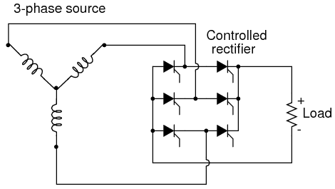
My power supply is all solid state - using a phase angle controller and a Semikron controllable bridge rectifier so I would expect it has a fairly ripple free 0-100V DC output, this is a fairly common set up in most other modern eddy controllers I have seen. Other older controllers that I have seen using a transformer and phase angle control the transformer is like 20Kg so your tiny little thing doesnt seem right.
Hi Ron,
If I understand you correctly, you have one SCR power supply that came with the retarder, and one PWM power supply for testing? The PWM power supply may be in limitation mode, and therefore dropping down to 70VDC, but scope it with a much lower time/div, and you will see what is really going on.
I'll concentrate on the SCR power supply:
To measure what is going on, you need to use the scope like you have done in the picture "full-controller-output-4.7vdc-power-box-out-to-absorber.JPG". Here, you can clearly see the two thyristors (or the triac) working as they should. Notice the steep start of the sine halfs, that is the point where the thyristor starts conducting. You can see the peak voltage of 153V, and this is the voltage as it comes from your 110V mains. Thyristor in action
The current draw is determined by the "load", in this case the retarder. As long as the power supply doesn't overheat, it is big enough for the application. (This is not true if the power supply has current limitation, but from your picture, you can see the full sine wave (almost), so the power supply is not in limitation mode.)
Re-wire your retarder to 192V and using your current power supply will half the retarder capacity. Re-wire to 192V and use a power supply that takes 220V main brings you back to square one.
If you calculate the average voltage supplied to the retarder, you will see that you are just under 100V, very much according to Klofts recommendations. If you dear pushing the retarder outside the factory recommendation, you need a different power supply. A three phase power supply would give you higher average voltage. (A PWM type is also a possibility, but they are pricy.) I don't think this is the way to go as you risk overheating the coils. Even the best insulating lacquer starts breaking down at approx 150°C. Also, a stronger magnetic field will put more heat into the rotors.
I suggest that you focus on the temperature of the retarder rotor. As the temperature increases, the holding capacity reduces drastically. Example: Retarder load chart with temperature degrading. Consider mounting a fan that forces cool air into the center of the retarder. This is especially nice to have if you need to pause your tuning because of hot retarder, as the fan will cool the retarder even when the retarder is stopped.
Also consider the gearing. When you do steady state tuning and the dyno cannot hold it, try using a higher gear. Mind your retarder max 5000 rpm. When you do ramp runs, the inertia will take some of the load away from the retarder, and hence you can brake more power when doing ramp runs.


