096 | Fault Finding Trigger Errors
Summary
Triggering errors are one of the most common problems we see with modified engines, and they can be frustrating and time consuming to diagnose. In this webinar we’ll discuss the common errors you’re likely to see and what to look out for when you’re on the dyno. We’ll also look at how to analyse the trigger inputs using a scope to visualise what’s going on and why you’re seeing errors.
| 00:01 | - I'm Andre from the High Performance Academy, welcome to this webinar where we're going to be discussing what in my opinion is probably one of the more common issues that you're likely to strike when you're on the dyno tuning and that's running into triggering errors. |
| 00:17 | When I'm talking about triggering errors, what I'm talking about is the ECU not receiving the correct information regarding engine speed and engine position. |
| 00:28 | Now this webinar follows on very closely from webinar 95 which talks about choosing the correct trigger inputs for a particular application so if you haven't already viewed webinar 095, I'd strongly suggest that you view that first, it's available in our archive right now. |
| 00:48 | It'll cover a lot of the information here which will make today's webinar, this particular webinar, make a lot more sense. |
| 00:55 | Now I'll point out that the webinar today is not going to be specific to any particular ECU platform, we're going to be looking at the fundamentals behind these trigger inputs and we're going to be seeing how those are affected, what the most common problems we see are, however I will be using some specific ECU examples to demonstrate these problems. |
| 01:21 | I'll also point out of course it's impossible in a one hour long webinar for me to cover off every possible scenario or problem that we might see with triggering problems in ECUs. |
| 01:35 | Certainly I've been in this industry now for 15 years and occasionally I'll still have a car on the dyno that shows me something that I haven't seen before so you need to take this on board and while I'm going to present the basics, the most common issues, there may still be some of your own diagnosis that's going to be needed in order to add to this and expand on it. |
| 01:57 | So let's start with how do we know if we've got a triggering problem when we're running a car on the dyno? How does a triggering issue manifest itself and there can be a number of ways. |
| 02:11 | And often this in itself can be a slightly tricky scenario because some problems with triggering can actually be the result of other issues such as noise in the ignition system affecting the ECU's operation so we do need to be a little bit cautious in our deduction of what the actual problem is. |
| 02:35 | The main issues that we're likely to find really come down from the fact that when there is a triggering problem, the ECU all of a sudden doesn't know what the correct engine speed is and it also doesn't know what the correct engine position is. |
| 02:51 | So at this point, often what it will do when it realises it's lost or out of sync is it will simply stop injecting fuel and it will stop providing spark until it's resynchronised and it knows where it is again and this we feel as an ignition misfire. |
| 03:09 | So as I've said, this can be problematic because there are obviously multiple reasons for ignition misfires. |
| 03:17 | It may be nothing at all to do with our triggering system and it may in fact simply be that the ignition system or the spark plugs are not up to task. |
| 03:26 | There are a few other aspects that will present themselves though if we are looking at a triggering problem. |
| 03:35 | Another common issue we will see is that we're going to have inconsistent power results from one run to the next. |
| 03:43 | And this is because if we've got inconsistent triggering the ignition timing, the fuel delivery will be inconsistent from one run to the next. |
| 03:51 | Particularly if we've got these triggering issues, not always happening at exactly the same point in the RPM, this can result in a real difficulty to maintain consistency from one run to the next. |
| 04:05 | So that's another key to look at, if you're getting that sort of run to run consistency issue then it may be that there's something that you need to look at with your triggering. |
| 04:15 | One of the most common problems I see, particularly on turbocharged cars is where we're running on the dyno and we're suffering from random and also inconsistent knock. |
| 04:28 | So if we're running the car up and we've just completed one run, our ignition timing is safe, we've had no knock and then on the next run, with no changes to our ignition timing perhaps, we all of a sudden have really aggressive and nasty detonation occur at some point in the run and this again is indicative that perhaps something's going on with our triggering system and the ECU's lost track of where abouts it is in the cycle, the timing's become over advanced and we've needed, we've ended up suffering from knock. |
| 05:03 | And this also goes hand in hand with the next problem which comes I guess a little bit with experience on a particular platform, particular engine, is the inability to provide what you would, your experience would show is typical timing for a certain engine. |
| 05:23 | And one of the examples that really sticks in my mind, because it was the catalyst for us creating our own SR20 cam angle sensor discs, was an SR20 DET and an S14 Silvia that I tuned many years ago, had a set of aftermarket cams which always goes to aggravate the problems with the SR20 cam angle sensor. |
| 05:47 | And what I found, this car was equipped also with larger injectors in a GT35 turbocharger and even a modest 15 psi of boost pressure, one bar of boost pressure on pump gas, I was struggling under boost to get anything more than about five or six degrees of ignition timing into the engine. |
| 06:08 | That was coupled with the power curve being nothing like what I'd expect to see. |
| 06:12 | The power curve came up pretty typically until the engine really started coming on boost and then the power became really erratic and dropped away quite dramatically. |
| 06:23 | So these are all indications that something wasn't right. |
| 06:27 | And in the end with only five or six degrees and an engine that I knew should be capable of perhaps 15 or 16 degrees, that again is a trigger for me that something isn't right and I needed to look deeper. |
| 06:42 | OK so we've got these problems, we've indicated that yes there is something wrong with our engine, it's not operating correctly so what's our next step, how do we go about finding what our problem is with our triggering? And really what we need to understand is what the fundamental causes or the most common causes of triggering issues are and I'm going to cover those off now. |
| 07:08 | So the first one would be a fundamental configuration error. |
| 07:13 | So this webinar I guess as well is already assuming that we've got an engine that's physically running so we know at this point that our basic configuration should be OK. |
| 07:25 | But we can also get into a situation where an engine comes to us for a tune and it's already up and running and it could be assumed, incorrectly, more often than not, that the configuration is correct and these configuration problems may not manifest themselves until we actually start running the car under load on the dyno and then we see that we've got a few problems to sort out. |
| 07:49 | A great example here would be the polarity issue with a variable reluctance or VR magnetic sensor and again I've covered this in webinar 95 but this is where the polarity of the reluctor style sensor is really critical, we can wire the reluctor sensor in either polarity, it's a two wire sensor typically and what that's going to result in is a completely swapped phasing of the signal and the edge that the ECU is triggering on is really critical so if we haven't got that polarity correct, that's going to cause a huge number of problems. |
| 08:30 | i'm going to cover off this in a little bit more detail again shortly. |
| 08:34 | The other aspect of course is that the current triggering system that we're using, the ECU simply can't process the data and a great example here is the Nissan 360 degree optical picky where we have 360 tiny little slots as our reference or trigger one input to the ECU which is giving it that information about engine speed or engine RPM. |
| 09:01 | Now that's driven of course off the camshaft so it's operating at half engine speed. |
| 09:05 | The ECU's receiving 180 inputs per engine revolution. |
| 09:11 | Now that in itself is one problem, we're giving the ECU a lot of data to process, particularly when we're talking about 7500, 8000 RPM. |
| 09:21 | The other problem which is actually more important though is because the cam angle sensor is being driven from a camshaft, we've got the valve train harmonics that are affecting that sensor as well and particularly with modified valve trains it's not uncommon to see this harmonic affecting the pickup and what we get essentially is the pickup can vibrate backwards and forwards, or resonate I guess is the correct term and the ECU then receives multiple pulses where it should only be receiving one. |
| 09:56 | So this gives the ECU the incorrect data to process. |
| 10:01 | The other problem is where we've got a trigger system where the trigger system is providing inconsistent information. |
| 10:12 | Now this is also really relevant to that Nissan cam angle sensor and covers what I was just talking about where the sensor will resonate and we end up with the disc moving backwards and forwards past the optical pickup so the ECU is receiving the wrong number of teeth per engine revolution. |
| 10:33 | A really common example here, which I'm going to talk about is where the sync position, this is the synchronisation position which tells the ECU which cylinder is firing at any particular time, where that is shifting relative to the reference teeth. |
| 10:52 | So let's just have a look now, if we jump to my laptop screen. |
| 10:57 | Now this is what's known as a ref sync capture from MoTeC's 100 series ECU. |
| 11:03 | Now this is kind of, you could think of it as an onboard oscilloscope which is really helpful because we don't need to have an oscilloscope and we also don't need to go to the trouble of hooking the oscilloscope into the trigger input so it's all built in onboard and what this does here is it just simply captures the data from, in this case, trig one and trig two, reference and sync in MoTeC speak. |
| 11:30 | And what we can see here is the yellow teeth that we can see, these are the reference input, so these are coming from the crankshaft. |
| 11:40 | It is a 12 tooth input and it is a hall GT101 style sensor. |
| 11:47 | Despite my warnings in webinar 95 about the downfall of the GT101 sensor, when used with a sensible pickup, it's still an effective sensor, we just need to understand its limitations. |
| 11:59 | So I'm not going to go through and count here but what we end up with, if we look at a complete engine cycle which I've just marked out, we have 24 reference teeth between every single one of our synchronisation teeth. |
| 12:14 | Now remembering that's because we've got a 12 tooth wheel on the crankshaft, however the single synchronisation tooth on the camshaft is turning at half engine speed so we end up with two complete revolutions of the crankshaft for every one revolution of the camshaft. |
| 12:34 | Now this ref sync capture is a great way of highlighting all manner of triggering errors and I'm going to be talking about the ref sync capture option and also oscilloscopes a little bit more in detail as well. |
| 12:50 | What we're looking for here, let's just zoom in a little bit and what we've got in this particular ECU, the MoTeC M800 is the ability to choose our triggering edge. |
| 13:03 | Now remembering that the ECU is expecting to see a synchronisation pulse after every 24 reference pulses. |
| 13:14 | Now if it doesn't see that then it knows something isn't right, if it sees the synchronisation pulse after 23 teeth, it's going to get confused and this is where our triggering errors manifest themselves. |
| 13:29 | So what we've got in this case is the ability to trigger off either the rising of the falling edge of both of our pulses, our reference as well as our synchronisation. |
| 13:41 | So for example let's have a look here, we've got a rising edge on our reference pulse here and our next rising edge on our synchronisation pulse happens to be here. |
| 13:55 | Remember what we really want to do here is make sure that our trigger input, our synchronisation input occurs as close to 50% halfway between our two reference inputs as possible. |
| 14:13 | So in this case if we look at our options we can see that choosing the falling edge on our sync input would probably be a pretty smart option. |
| 14:26 | Now let's have a look at our other options here, in particular, if we had chosen to trigger on falling edge, on our reference input, so we would be triggering here, and on our next tooth we'd be triggering here. |
| 14:42 | And if we'd also chosen to trigger on the falling edge of our sync pulse. |
| 14:46 | Now you can see how we can get ourselves into trouble. |
| 14:50 | We can see that the sync input is now happening incredibly close to our reference input and it's not going to take much movement, which can come from cam belt stretch, cam chain stretch or resonance in the cam valve train itself, in order for the sync tooth to move enough that that edge just jumps to the other side of our reference input and that's going to be enough for the ECU to register a triggering error. |
| 15:22 | Now the problem with this is what's happening at idle is not necessarily relevant to what's happening at 8000, 9000 or 10,000 RPM either. |
| 15:32 | And through those aspects I've just mentioned, cam belt or cam chain stretch and resonance, it's still possible to see the sync position move around, what we want to do is make sure that it's located so that it gives us the widest window possible to avoid it swapping edges and bringing in a triggering problem like that. |
| 15:55 | The other aspect that is also a common cause of our trigger errors is noise. |
| 16:02 | And this is particularly relevant on the ignition side of our ECU. |
| 16:08 | In particular, one area that I've struck problems with in a number of applications is where customers have fitted non resistive spark plugs and these tend to create a lot of noise in the ignition system, this can in some cases be transferred into the ECU and can cause all manner of problems, not necessarily just in the triggering. |
| 16:34 | This is, I would have to say, dependent on the ECU, some seem to be much more tolerant of noise like this than others so I can't really give you an across the board situation where you could say that all ignition systems must run a resistive spark plug but certainly in my experience, I would find that more often than not, a resistive spark plug is certainly a good option and a safer option than a non resistive spark plug. |
| 17:04 | OK so now we know we've got a problem, we know what the main causes of our problems are, I should actually also add the usual suspects for those problems would also include wiring faults, hands down the most common issue for any tuning related problem across the board but this can of course come across into our triggering as well. |
| 17:30 | Of course as well as a dud trigger sensor trigger input on its own. |
| 17:35 | So those are our main causes so now we've got, we know we've got a problem, we know what we're looking for, how do we go about our diagnosis? One of the first places to start is by having a look at some of our data and seeing if what we've got is believable. |
| 17:57 | So let me just have a look here at our laptop screen, I'll just get this out of the way for the moment. |
| 18:06 | So this is a simple ramp run on an FD RX-7 and what we want to do is look at a few parameters and see if these are making sense. |
| 18:17 | First of all what we want to do is look at our maximum RPM value. |
| 18:22 | And in this case, I'm not actually displaying a maximum, this is just a log file. |
| 18:28 | Most ECUs will have the ability to view a maximum and a minimum value for any of our parameters while the engine's been running. |
| 18:36 | So if we're running our car up and let's say it runs to 7000 RPM, after a dyno run we were a little bit suspicious about the behaviour, we look at our maximum and minimum values and we find that the RPM's registered 14,000 for example, or 50,000, something completely unrealistic and unbelievable. |
| 18:55 | This is a really good indication that we may have a problem so that's the first place to start, a really quick glimpse at what our maximum RPM value is. |
| 19:07 | The other aspect, and this will vary from one ECU to another on how we can view it, I'm just going to use the Link ECU here as a great example. |
| 19:16 | And if we click R or F12, we can bring up our run to run time values screen which we can see right here. |
| 19:23 | What we want to do is click on our triggers and limits tab and this is really one of the first places that I will go is our trigger status. |
| 19:32 | Now when we're first trying to get our engine running, we'll have our trig one signal and our trig two signal which are currently indicating no, our engine's not running. |
| 19:42 | When we're cranking the engine when the ECU is physically receiving inputs from these two signals, these will both go green and say yes. |
| 19:50 | Now as I've said, this isn't a webinar about getting your engine running for the first time so we're already assuming that's the case however when we've got our engine running the ECU is also constantly looking at this triggering system and it's updating this trig one error counter. |
| 20:07 | So any time the ECU detects either a missing trig one input, so in Link speak, trig one is the reference input, this is giving us engine RPM data. |
| 20:19 | So any time it either detects too many or not enough trig one inputs between every trig two input, it's going to increment this trig one error counter. |
| 20:29 | So in the perfect world we'd like to see exactly what we've got now, a value of zero. |
| 20:34 | It's not uncommon however when we first start the car for the ECU to log one or two trigger errors while it's first getting synchronised. |
| 20:44 | So it's not necessarily a bad thing if we see this error counter sitting at perhaps one, two or three. |
| 20:51 | What we're really looking for though is during a ramp run on the dyno, any time the engine's operating under high load and RPM, we shouldn't see this error counter increment, it should stay absolutely rock solid at whatever it was before we started that ramp run. |
| 21:07 | So that's our first indication there, the other thing that's worth looking at as well is we have a parameter here called engine speed rate of change so this is showing us how quickly our engine RPM is increasing. |
| 21:21 | Now it's not particularly useful viewing it here live in real time while we're running the engine, we can also log that parameter which is going to give us some information. |
| 21:32 | So let's close down our run time values, so we've already considered we're going to look at our trigger error counter and we're going to look at our maximum RPM values. |
| 21:42 | There's also a lot of information we can simply take straight from our logged data and of course in the Link ECU, we can do this live while the engine's running just by pressing F8 and we're going to get a log that we can view live like this. |
| 21:58 | Now what we're looking for here particularly we're going to be focusing on our engine RPM trace initially. |
| 22:06 | And you can see that for the most part I've got this nice, smooth green line that's really incrementing very smoothly and consistently. |
| 22:17 | Now if our triggering system's working and obviously our dyno's controlling our ramp speed correctly, this is exactly what we should expect to see. |
| 22:28 | One of the keys to look for if we've got triggering problems is this isn't going to be what we'll see and we're going to end up with a sharp spiking, maybe not quite as dramatic as I'm trying to draw but I unfortunately don't have anything that I can show you here as an example. |
| 22:45 | So we're going to get some spiking in the RPM. |
| 22:48 | And quite often as well what we'll find is that a certain RPM range is going to cause a more resonance or a harmonic that is going to cause more triggering problems than other RPMs so we may find that at a certain RPM we see this really start getting out of control and then it may settle down again as we continue to climb in our engine speed. |
| 23:13 | Now this is also going to be able to be viewed if we're looking at our engine speed rate of change parameter which I've got logged here. |
| 23:22 | So you can see for this particular log file, our engine speed rate of change again is staying reasonably consistent. |
| 23:31 | So if we're starting to see our engine speed rate of change doing all sorts of crazy stuff like this, then that again isn't particularly realistic and indicates that we've got some bigger problems to look at. |
| 23:45 | Finally at the bottom of this particular graph, I'm also logging our trig one error counter which in this case is pretty uninteresting because we've got a value of zero right the way through the run which is exactly what I'd like to see. |
| 24:00 | So we can see there's a huge amount of data that we can take away from our log file that's going to give us a lot of insight into how well the ECU is receiving those trigger inputs and let us know where we need to focus our attention. |
| 24:18 | Now the other thing we can do of course once we know that we've got a triggering problem is to scope the trigger inputs and we looked just briefly before at the trigger scope function on the, sorry it's called a ref sync capture in the MoTeC M800 ECU. |
| 24:38 | I'll just pull this one up so its visible again on our laptop screen and that's not particularly helpful, what have we got here? Let's try getting a little bit more resolution here. |
| 24:51 | So the trigger scope system on the Link G4 platform. |
| 24:58 | This is something that's been around for a while, we can get to that by going to the ECU controls menu and go down and click on trigger scope and as I've mentioned it's essentially a built in oscilloscope that's just going to show us what our trigger input pattern is looking like. |
| 25:15 | So we have our trig one input shown on the top, we've got our trig two input shown on the bottom. |
| 25:22 | Now this is a capture that I did just before we came live on the VQ35, it's a little bit unique in so much as this is a cam control engine so we have some data here that is giving the ECU information about the camshaft position as well as synchronisation data that tells the ECU which cylinder is firing at any time. |
| 25:44 | As you've just seen me do, we can manipulate the way the data is displayed by adjusting the voltage per division and also the time per division, should be pretty run of the mill stuff for anyone who's ever used an oscilloscope before. |
| 25:59 | The beauty of using a system like this as well is if you really do get stuck, what you can do is you can save the capture and then you can email it through to the techs at Link and they can help you with diagnostics on what's actually going wrong. |
| 26:16 | Now if you haven't got an ECU that provides a trigger scope or oscilloscope functionality, in the old days, probably when I first started in the industry, oscilloscopes were quite an expensive piece of equipment, they were also quite cumbersome. |
| 26:35 | Now we can get these little USB oscilloscopes that work straight onto your laptop and they just are so affordable, there's really no reason not to have one. |
| 26:46 | So this is a PicSscope. |
| 26:48 | I think if I remember correctly, this is probably one of their entry level models, it's pretty basic. |
| 26:54 | And I think you can get these for under about $150 USD so for that sort of cost, the hours it can save in diagnostics are just invaluable. |
| 27:03 | It is essential to make sure you're getting at least a two channel oscilloscope because you really want to be able to view both your reference and synchronisation pulses overlaid with each other. |
| 27:16 | In some cases it may be beneficial to have a four channel scope so you can look at cam position sensors, synchronisation sensors and reference sensors on slightly more advanced engines. |
| 27:29 | But this is really so cheap and affordable, it's just, there's no excuse not to have one these days. |
| 27:36 | Of course there is a bit of a learning curve with any product and for those of you who have never used an oscilloscope, they do take a little bit of time to get your head around but again well worth the effort. |
| 27:48 | So the scope function that's going to let you visualise exactly what's going on with your particular triggering inputs. |
| 27:56 | Beyond that, we need to look at the triggering setup as well. |
| 28:04 | Now one of the common problems that we see, and again this was discussed briefly in our webinar 95, is where we've got a hysteresis curve or an arming threshold curve for a reluctor sensor that hasn't been correctly configured. |
| 28:23 | Now I'll just go over that just briefly, let's just drop back to our laptop screen. |
| 28:28 | I'll go back into our tuning and what I'll do is I'll just set this up, this is a hall or optical input but let's, on our VQ35, let's just set this up for the moment though as a reluctor input, that's going to turn off our option for a pull up resistor and instead we're going to get our arming threshold table. |
| 28:49 | So this is a two dimensional table of, in Link lingo, this is arming threshold versus engine RPM. |
| 28:58 | Now let's see why we need this. |
| 29:01 | What we're going to do is I'll try my artistic skills again so bear with me, I'll try my best here. |
| 29:08 | What we're going to do is just draw a quick diagram of what our reluctor input looks like. |
| 29:15 | And so we have our voltage, no that's not going to work is it. |
| 29:20 | We'll have our voltage over here so we've got our plus and we've got our minus and what we find is that the signal looks something like this. |
| 29:32 | Yeah that's pretty good actually, maybe I would have made an artist after all, missed my true calling. |
| 29:38 | Alright so we've got a signal that looks something like this. |
| 29:40 | Now the problem is that the voltage that we're seeing, so here our peak voltage, this is really dependent on the engine RPM. |
| 29:50 | And what we need to do is set this two dimensional arming threshold table, it's also known in MoTeC lingo as a hysteresis table, we need to set this so that the ECU knows when it should expect a trigger input to occur. |
| 30:07 | So my rough rule of thumb here is we set this arming threshold at about a third of our peak amplitude. |
| 30:15 | So in this case we'd be somewhere down here. |
| 30:17 | And in a nutshell what happens is as the voltage rises past our arming threshold, the ECU goes OK right I know that I'm about to see, I'm about to receive a trigger input so it's armed and it's ready, that's why Link call it the arming threshold. |
| 30:32 | Then what happens is the voltage rises up, it peaks and it drops vertically back through our zero volt threshold. |
| 30:39 | And it's at the point right here where the voltage passes through zero that the ECU actually triggers. |
| 30:48 | Now that's great at this particular RPM. |
| 30:51 | I'll just move over here and draw it again, this is what happens when we increase our RPM though, we see that our peak amplitude starts increasing quite dramatically. |
| 31:02 | And it's not uncommon to see these sorts of reluctor inputs provide a signal that may only be a few volts peak to peak or less at idle and low RPM. |
| 31:14 | However at high RPM, we may be seeing 20 plus volts coming out of one of these sensors. |
| 31:20 | So what we need to do is adjust our hysteresis or arming threshold to suit the engine RPM. |
| 31:26 | So you can see again if we work on our basis of around about a third of our peak amplitude, you can see that we're dramatically higher than whatever RPM we were at when I drew this graph. |
| 31:37 | And getting this right is really critical so a common problem here is where the arming threshold is being set too high, in which case if the voltage, the peak voltage from the sensor never reaches the arming threshold, the ECU's just going to completely ignore that signal and it's going to consider that signal to simply be noise. |
| 31:59 | So the ECU just won't receive an RPM input, it'll stop operating. |
| 32:04 | So that's one of the key, one of the common problems I see and we need to be aware of that. |
| 32:10 | At the flipside of that though, if our arming threshold is set too low, the very reason we have this arming threshold is so that the ECU can ignore the inevitable noise, background noise that we're going to have on this input which also unfortunately, but understandably does tend to increase with engine RPM. |
| 32:30 | So we want our threshold to be high enough to ignore the background noise, so we're only really concentrating on the signal and at the same time we need it low enough so that the ECU is genuinely able to synchronise. |
| 32:45 | So again we can use our scope or our trigger scope functionality in an ECU if we've got it in order to decide what the correct triggering arming threshold is for our particular engine. |
| 33:00 | Once we've got that understood we can go back and we can fill in our table here. |
| 33:06 | What we'll find often is that our ECU will be filled in with a generic or default table which is exactly what I've just brought up here and in most instances this may just work straight off the bat. |
| 33:21 | So this is a table that a lot of tuners won't understand because they've simply never needed to adjust it or play around with it. |
| 33:29 | However you will still find the odd occasion where all of a sudden your reluctor pickup isn't working correctly, isn't working with this default table and you need to actually break out the scope and figure out what's going wrong and correctly adjust it. |
| 33:46 | While I'm talking about that, again this is really more about getting your engine running for the first time, I've found particularly, this seems to be common with a number of Toyota engines where they're quite fond of their reluctor pickups and the voltage output at cranking speed is generally, or quite often very low from these engines and quite often what we will find is we get our ECU set up and configured, go to crank the engine and we're simply not getting any input from the trigger input at all, trigger one. |
| 34:18 | What we can do there to rectify that is drop the arming threshold at zero RPM down very low, perhaps even as low as 0.1 volts so it's able to actually see and register that signal so that's a little trick there, as I say, something I've seen most frequently on Toyotas but if we're using our trig scope, our trigger scope, we're still going to be able to see exactly what's going on there anyway. |
| 34:49 | OK so let's go through our common, fixing our common trigger errors so the first place to start of course is to check our basic configuration of your trigger mode. |
| 35:04 | Now this should go without saying but again often overlooked so have you got the correct trigger mode selected for your particular engine? While in a late model engine such as our VQ35 here in our 350z, it's probably unlikely to run on anything but the correct OEM style trigger mode, there is certainly situations where engines with much simpler trigger systems will operate potentially on an incorrect trigger mode and that might work at idle but it's likely to show its head as being a real problem once we get higher in the RPM. |
| 35:41 | So the key here I guess is really should go without saying, don't ever assume that the configuration is correct and if you've got one of these problems, you need to go back and check and confirm. |
| 35:54 | Once you know you've got your correct trigger mode selected, particularly if you are using a reluctor pickup we want to make sure that we're using the correct polarity. |
| 36:07 | Now some ECUs will actually allow us to connect the reluctor pickup in either polarity and then we can choose the edge that we're going to trigger off. |
| 36:17 | In other situations, we need to wire the pickup in one particular manner. |
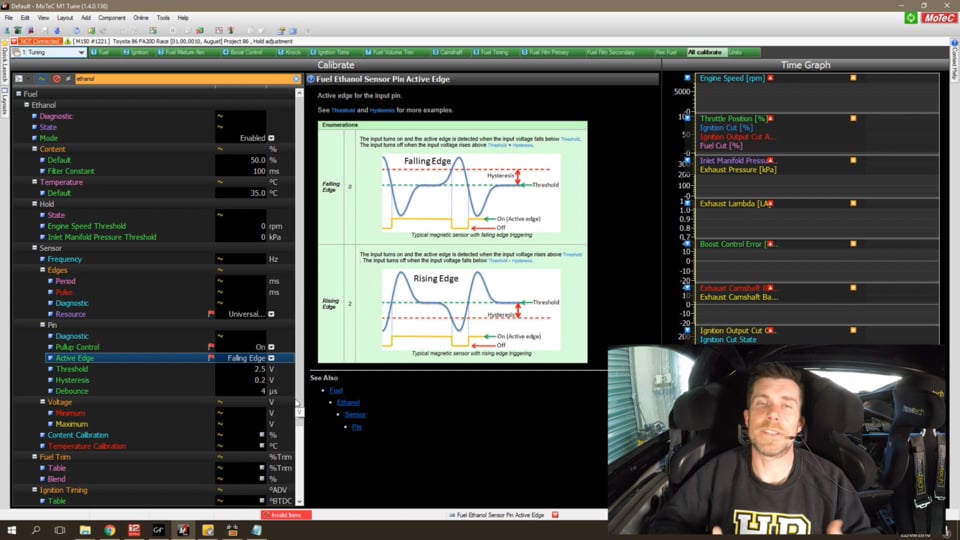
| 36:25 | Now what I'm going to do is jump to my laptop here and I'm actually going to show you a nice help file that MoTeC have on this, it just makes it easier than me drawing it which demonstrates both falling edge trigger and rising edge...control the trigger edge. |
| 36:41 | This is a falling edge reluctor trigger. |
| 36:43 | If we wire that sensor in the opposite manner though we get a mirror image of our voltage and we can see that now this time the voltage begins by dropping through zero to a negative voltage and then we see it rise sharply back through zero. |
| 37:01 | So in this case this would be set up if we had the option as a rising edge trigger. |
| 37:06 | If we don't have the option of setting a rising edge trigger in our ECU, then we need to swap the polarity and when we swap the polarity, lo and behold we'll end up with a signal that looks like this and it's something the ECU can work with. |
| 37:21 | So really critical, a really common area that people overlook. |
| 37:25 | Now we've already talked about the arming threshold or hysteresis for the VR sensors, probably a little bit out of order so again, I'll reiterate, you must make sure that that's correct. |
| 37:39 | Now another aspect that ECUs will offer, again they come under different names, in MoTeC lingo it's called debounce which might on the face of it not seem overly useful and what it is, in other ECUs it's quite commonly referred to as a filter. |
| 37:58 | What it is is a way of the ECU being able to reject high frequency noise on these inputs so it's another way of just stripping away the background noise that's always likely to be present and allowing the ECU a better chance of recognising just the signal so again this little diagram here in the MoTeC help file shows us kind of how this works. |
| 38:22 | So we've got our blue line here which is our trigger input, or our particular input from the sensor. |
| 38:29 | And what we have is a debounce value set here and essentially what this means is that any pulse, in this particular instance the debounce value is 50 microseconds so any pulse that is shorter than 50 microseconds will be ignored. |
| 38:47 | Likewise over here on the right hand side we now have a wider input and you can see this is now wider than the debounce value, it's 70 microseconds so this will be registered by the ECU as an input. |
| 39:03 | So filtering, it works essentially in a similar manner, it's a hardware way of the ECU ignoring high frequency noise and focusing on the signal. |
| 39:14 | What we do need to be careful of though is if we apply too much filtering we can actually start ignoring the signal and this is particularly relevant in trigger inputs that offer a high tooth count or a high input frequency. |
| 39:31 | We're going to need, by their very nature with high frequency inputs like that, to use minimal to no filtering. |
| 39:40 | And this can also be considered I guess a little bit of a bandaid for a trigger system that's perhaps not optimal. |
| 39:49 | If we need to apply a lot of filtering in order for us to get a workable or usable result. |
| 39:56 | The other thing, just talking about our reluctor polarity here, and I'll just cover this off again because it is a really easy thing to test very early on in your tuning process, is simply checking to see if we're getting timing drift as we increase our RPM. |
| 40:15 | And this technique's a great way of checking the reluctor polarity is correct. |
| 40:20 | So what we want to do here is set our ECU into base timing mode and we want to fix the timing at a certain angle that we can easily see with our timing light, let's say 10 degrees. |
| 40:33 | And we want to adjust our base timing until we are exactly on 10 degrees and then we can smoothly increase our engine RPM from wherever we were setting our base timing, let's say idle at maybe 800 RPM, we can increase the engine RPM up to 3000 or 4000 RPM and over that period we really shouldn't see our ignition timing move more than perhaps a degree or so, it should be essentially pretty rock solid across that sort of RPM range. |
| 41:02 | If on the other hand we've got a polarity problem with our reluctor sensor, we're going to see quite a large swing in our ignition timing as we go through that test. |
| 41:12 | And if we're seeing more than about a degree of ignition swing, that's going to indicate to us that we may have a problem with our reluctor polarity, that's going to indicate that that's a place we need to go and test. |
| 41:25 | Right now I'm going to move into some questions and answers very shortly so if you do have any questions, now is a perfect time to ask those in the chat box and Ben will transfer those through to me. |
| 41:38 | So what I want to do is just go over a little bit of a recap of what we've discussed here and remember the first thing to consider is what we're actually looking for to decide that we may have a triggering issue. |
| 41:54 | So the keys here, we're looking for an RPM, a maximum RPM reading, sorry I'll start again. |
| 42:03 | We're looking at an engine that is erratic in its operation. |
| 42:07 | We're looking for an engine that is inconsistent from one run to the next on the dyno. |
| 42:15 | An obvious one would be an ignition misfire that we can't seem to fix with changes to our ignition system. |
| 42:22 | Perhaps an engine that is randomly and inconsistently suffering from heavy detonation. |
| 42:30 | And of course an engine that's not going to take the sort of ignition timing that we know from experience that it should. |
| 42:39 | So the causes for these triggering problems, obviously we have the fundamental configuration error with our triggering system, we've got a system where the ECU simply can't process the amount of data that it's receiving from the triggering system. |
| 42:56 | Or we're getting a problem where the triggering input to, data to the ECU is becoming inconsistent. |
| 43:04 | So the two examples I gave there were the Nissan cam angle sensor and also the situation where our synchronisation pulse is occurring too close to a reference pulse and is swapping from one side to the next randomly, affecting the number of reference teeth that the ECU is seeing per synchronisation event. |
| 43:27 | The other issue of course is the noise on the ignition system. |
| 43:33 | Now remembering where we start with our diagnosis on that, always a great place to start if we simply view the peak RPM that's been recorded during a dyno pull and ensure that that's somewhat believable. |
| 43:47 | If we're seeing massive values like 10,000 or 20,000 RPM, then that would be reason for concern. |
| 43:56 | We can also view the rate of change of RPM if that's a logable parameter. |
| 44:00 | Are we seeing any trigger errors? Is our RPM trace in our log data smooth and consistent as we'd expect to see? We're not expecting to see massive fluctuations in that. |
| 44:13 | Finally we can scope those trigger inputs as well and physically see what they're doing. |
| 44:19 | And then finally, fixing those trigger inputs, checking on your basic configuration, making sure that we've got our polarity of our triggers correct for variable reluctor, making sure that our arming threshold or hysteresis is correct again for variable reluctance sensors and checking for timing drift and finally again scoping those inputs to see what's occurring. |
| 44:45 | Alright hopefully that's covered everything, well as much as I can, as I said at the beginning of the webinar it really is impossible because it is such a broad topic for me to cover every single problem that you may encounter but these certainly are the most common ones that you're likely to come across. |
| 45:02 | Just given my own personal experience. |
| 45:05 | Our first question comes from Tyler who's asked, what problems with sync can a crank only sensor have? OK of course if you are running a crank only sensor where you're not running sequential, so you're running perhaps a input per TDC or maybe a missing tooth trigger wheel on the crankshaft then for the most part that is certainly going to make your life easier because we're not going to have problems with the synchronisation position and that's really probably one of the most common problems when you're running a reference and a synchronisation input. |
| 45:44 | However that doesn't mean that you're immune to problems. |
| 45:47 | First of all, we have probably the most common multi tooth input, so let's say a 36 minus 2 60 minus 2 inputs, do work with reluctor inputs so in that case, you've still got the issues of the ECU being able to process the data, both of those should be pretty easy because they are OE styles of trigger inputs but with the reluctor input you do still need to have your arming threshold set correctly and that's something you will need to watch. |
| 46:20 | So you're still not completely out of the woods if you're not running a synchronisation input. |
| 46:25 | Maims has asked, what sort of oscilloscope bandwidth is required, e.g. what is the highest frequency usually observed when probing these sensors? That is a question that right here I can't answer you because this is a question I had to go through when I was selecting our PicoScope and honestly I can't remember what the answer to that was. |
| 46:53 | What I do know is as the bandwidth of your oscilloscope increases, so does the cost. |
| 46:59 | And I'm pretty confident that the PicoScope that we ended up with was one of the very most basic entry level with the lowest bandwidth but leave that with me and I will come back to you in the forum and give you a little bit more update on that. |
| 47:16 | Tyler's also asked, will the RPM measured by a crank position sensor vary greatly in a single cylinder engine? OK so what you're talking about here is going to depend on the actual crank sensor itself and how many teeth that pickup has. |
| 47:34 | So particularly if you're talking about a single cylinder engine, if we look at the engine speed relative to a complete engine cycle, it's not going to be consistent, we have the engine speed fluctuating depending on where abouts in the engine cycle the engine actually is so it's going to tend, if you think about it, just common sense, it's going to tend to slow down on the compression stroke as the cylinder is compressing the fuel and air charge, obviously it's going to accelerate away on the power stroke where that fuel and air charge is exploding and providing energy to the top of the piston. |
| 48:13 | So if we're looking at a trigger input on the crankshaft that's very low in its resolution, so let's say for example, it's a four tooth pickup so it gives very little information, we're only getting information about engine speed or what's happened to the engine speed four times per engine revolution. |
| 48:33 | So what happens is that the ECU assumes from one sample to the next that the engine RPM is consistent, obviously that may not be the case and what we can see, how this manifests itself is if we're got a timing light on the engine, particularly at very low RPM, we're going to tend to see the ignition timing fluctuate slightly because of the inconsistency in the engine RPM versus what the ECU is sampling or think's going on. |
| 49:03 | If we went to a 12 tooth wheel, we're getting a lot more data now, we're getting three times the data, the ECU can do a better job of measuring the actual changes in engine speed during the engine cycle and hence can keep things a lot more consistent. |
| 49:17 | In a way though, what we do need to understand is as the engine RPM increases simply because the ECU is now seeing more inputs, the timing does tend to become more stable anyway so this is an issue that really shows itself up more at very low engine speeds than it does at higher RPM. |
| 49:43 | TDE Champ has asked, how does the resolution timeframe selection and voltage compare to Pico or Snap On scopes? I'm assuming there what you're talking about is the trigger scope output that I showed you on the Link ECU or the MoTeC ECU and really the way that works is essentially the same as any oscilloscope, we can select our voltage per division as well we our time per division and those selections will be the same as what we'd expect to see with any oscilloscope. |
| 50:20 | Alright guys that's brought us to the end of the webinar, some great questions there. |
| 50:23 | Hopefully this is really going to help you guys out when you are struggling with some of these triggering problems that you're inevitably going to see on the dyno. |
| 50:32 | As usual, if you do have any more questions that crop up after this webinar has aired live, please make sure you ask those in the forum and I'll be too happy to answer them in there. |
| 50:44 | Thanks for joining us and I look forward to seeing everyone next week. |


