097 | Configuring a Strain Gauge Gear Lever
Summary
If you’re using a dog engagement gearbox for motorsport use then often the use of the clutch is optional, however for the best results the ECU needs to know when the driver is trying to change gear. A common option is to use a gear lever fitted with a strain gauge and in this webinar we’ll discuss how the strain gauge works, how to interface it with your ECU, and how to use the signal to achieve smooth clutch-less shifts
For this webinar we’ll be using the Motec M150 ECU.
| 00:00 | - Thanks for joining us for this webinar, I'm Andre from the High Performance Academy and in this webinar we're going to be investigating strain gauges, particularly in the application, or solely really in the application of gear shift. |
| 00:14 | So this is quite a common way of interfacing with your ECU to allow the use of flat shifting or clutchless shifting with dog engagement gearboxes. |
| 00:27 | And this is a feature that's being integrated or used in more and more current models of ECU and as we're seeing more people in competition applications moving to dog engagement gearboxes, it makes sense to get the most out of those gearboxes by using a strain gauge gear lever so that you have that option of clutchless shifting. |
| 00:52 | Now before we move on, I'll also point out that while it might sound strange, using a properly configured strain gauge gear lever, along with a properly configured gear cut strategy in your ECU can actually go a long way towards prolonging gearbox life and ensuring consistency of gearshifts. |
| 01:13 | Particularly if your ECU is performing complete closed loop control, and we're going to be talking more about that shortly. |
| 01:23 | Now in this webinar, we're going to be focusing mainly on the fundamentals here so what is a strain gauge, how can we use a strain gauge and what do we actually need to consider with the configuration of a gear shift strategy? So we're going to be focusing more on the fundamentals rather than a particular application as we often do in these webinars. |
| 01:46 | However I will be going through some examples, particularly with some datalogging to kind of help emphasize what I'm talking about and I will be doing that using MoTeC i2 and a couple of examples that we have done through High Performance Academy which were based on the MoTeC M1 platform so I will be trying to relate these to the wider application of the technology as opposed to just what it will do on a MoTeC ECU. |
| 02:18 | Of course, if you do have any questions, we will be having questions and answers as always at the end of the webinar so I urge you if you do have anything you'd like me to go into detail about, please ask those in the chat, Ben will transfer those through to me and I'll do my best to answer them. |
| 02:36 | OK so let's start with what exactly is a strain gauge? And if we can just jump to my laptop screen, this is probably a fairly familiar sight with a lot of late model competition gearboxes. |
| 02:52 | So the photo right here is actually of a fairly modified Ford RS200 group B car. |
| 02:59 | And it's been fitted, retrofitted with a 6 speed sequential gearbox and the part that we're really interested in here is what looks like a fairly uninteresting gear lever. |
| 03:12 | But the key point here, if we are a little bit sensitive to what's going on and we look down the bottom, we can see that there's a little white lead coming out of the gear lever and this is part of the strain gauge assembly. |
| 03:27 | Now a strain gauge is simply a way of the ECU being able to monitor what the driver is essentially doing on the gear lever, whether the driver is pulling backwards on the gear lever, pushing forwards on the gear lever and how hard they're doing it. |
| 03:43 | So let's have a look at what a strain gauge is, what makes up a strain gauge and zoomed in, this is kind of what a strain gauge looks like. |
| 03:51 | So it's a really small thin sensitive piece of equipment and what we can see here is we have kind of a grid of foil that's bonded to a very very thin backing. |
| 04:05 | And what happens is that this strain gauge is bonded normally glued to the shaft of the gear lever and it's very sensitive to tension or compression forces, in this case we can actually see, in this particular direction. |
| 04:26 | So it's bonded onto the shaft or glued onto the shaft in a way so that as we move the gear lever, the resistance or the strain gauge is deformed and this results in the resistance of the strain gauge fluctuating as we push or pull on the gear lever. |
| 04:48 | Now they are very very sensitive but on their own, they're also not much use. |
| 04:54 | So the sort of resistance changes that we see out of a strain gauge are incredibly small. |
| 05:01 | And in order for us to interface a strain gauge with our ECU, the strain gauge is normally going to be connected to what's known as a strain gauge amplifier that takes these incredibly small changes in resistance that we're going to see and then converts them to something that we can use in our ECU which will typically be 0 to 5 volt output. |
| 05:25 | So once, we've seen now what the strain gauge looks like in a diagram form. |
| 05:30 | Let's have a look, this is what they actually look like in real life. |
| 05:34 | So you can see here, the strain gauge is glued to a shaft and then if we take that one step further. |
| 05:44 | No we won't take that one step further, I didn't manage to get that picture, doesn't really matter. |
| 05:50 | If we take that one step further then what we see on a gear lever that we've sent away to a manufacturer to have a strain gauge fitted to is it'll generally be covered with a heat shrink boot as well so we'll end up just with a lead coming out of that that'll either, that'll go to our strain gauge amplifier and then furthermore it's going to end up going into our ECU. |
| 06:18 | So we know what the strain gauge is now, we know how they're applied to our gear lever, why do we want one and what use are they? So I've kind of touched on this, the strain gauge, because it can monitor what forces are being applied to the gear lever, and it's incredibly sensitive, we can use the output from the strain gauge to tell the ECU when the driver is pulling back on the gear lever, essentially requesting a gear shift to take place. |
| 06:54 | And because the output of the strain gauges is dependent on how hard we're pushing or pulling on the gear lever, we can use this to decide exactly when we want to trigger the shift event to occur. |
| 07:12 | So in order to understand this in a little bit more detail, we probably also need to have a quick discussion on how a dog engagement gearbox works. |
| 07:23 | And I'll apologise for any of you who are already very well schooled up on dog engagement gearboxes. |
| 07:31 | I'm just going to cover this off again because they are quite dramatically different to the synchro mesh and a lot of what we can achieve with a dog engagement gearbox is really dependent on how they work internally so I'll just cover this off for those of you out there who aren't aware of how a dog engagement gearbox works. |
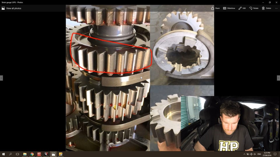
| 07:51 | We've got a diagram, or sorry I've got a picture here on my laptop screen that we'll look at. |
| 07:56 | So this is a gear set from a dog engagement competition gearbox and here we can see we've got our gears. |
| 08:05 | These are straight cut gears which isn't really that relevant to dog engagement application at all. |
| 08:13 | It's not really the gears we're worried about, it's how the gears are selected. |
| 08:17 | So here we can see between these two gears we have a selector fork and this is what is being controlled by the driver when we're making a gear shift. |
| 08:28 | So what essentially happens is that, let's say we're in 3rd gear here. |
| 08:35 | And this selector fork that we can see, in this case is located upwards, so it's engaged in third gear and then we want to change into 4th gear. |
| 08:47 | So what would happen is that this selector fork then would move down, it would then deselect the top gear, third gear and it would engage and select the lower gear, 4th gear. |
| 09:01 | And the key point is how the gears are selected and this is through what's referred to as drive dogs. |
| 09:09 | And we've got a close up of what these look like on the right hand side. |
| 09:13 | So first of all at the bottom of the photo, this is what each of the individual gears looks like. |
| 09:20 | So we obviously have our gear teeth which we can see on the photo on the left but you can see we also have these little bumps on the top surface of the gear. |
| 09:31 | In this case, this particular gear has 4 of these little bumps and these are known as dogs. |
| 09:38 | Now the selector, which we can see up here on our top photo, this is what we can see here on the left hand side of our photo as well so the selector is the part that the driver is physically moving through the gearbox mechanism. |
| 09:53 | So when the gear selector moves, it moves this dog ring which we can see. |
| 09:58 | And the dog ring has 4 matching drive dogs. |
| 10:03 | And it has these on the top surface as well as on the bottom surface. |
| 10:08 | So what it's done, let's say that we're in 3rd gear and we can see we've got our gear up here, so the selector ring is in this case, located up. |
| 10:20 | So it's engaged with the drive dogs on the top gear which we can see. |
| 10:27 | Then what we want to do is change gear, so we're going to pull this selector down and now it's going to disengage with these dogs at the top, it's going to move down and these bottom dogs, this time are going to engage with the dogs on the next gear, in this case we're going from let's say 3rd to 4th gear. |
| 10:48 | So it can be an incredibly fast shift because we have quite a large window where the dogs can mesh correctly, so this allows the dogs to mesh very quickly and accurately even at high engine speeds. |
| 11:04 | And this is one of the keys with the dog engagement gearbox is unlike a synchromesh box which can get very difficult to shift at high RPM, much over about 9000 RPM you're going to start having problems with synchromesh gearboxes, dog engagement gearboxes work incredibly well just about regardless of the engine speed. |
| 11:25 | Now the other key aspect here is that all of these dogs, which is a little bit hard to see in this photo, actually have a slight back cut on them. |
| 11:37 | So the surface, I'll just try and draw it, try and draw it here, the surface here, nope, try this one. |
| 11:49 | The surface here actually has a slight back cut on it. |
| 11:54 | So if we're looking at the side of the dog, it looks a little bit like this. |
| 12:01 | And that back cut means that once the drive dog is engaged, the selector is engaged with the gear and we've applied engine torque, that actually pulls the dogs together, that back cut engages the dogs and it makes it virtually impossible for the gear to pop out. |
| 12:22 | OK so this is a key point because when we want to change gear with a dog engagement gearbox, we need something, regardless of whether we're looking at an upshift or a downshift, we need something to allow the dogs to release and this requires a torque reversal. So traditionally we would use the clutch potentially and generally when we use the clutch, we're also going to back off the throttle. |
| 12:46 | As soon as we back off the throttle, obviously we reduce the engine torque and this allows the drive dogs to disengage, allows us to very quickly and easily pull into the next gear. |
| 12:56 | So that's how we traditionally change gear. |
| 12:58 | Of course with dog engagement gearbox that's quite a slow process and this is why we look at alternatives. |
| 13:06 | So the other option that a lot of drivers used to use before modern electronics made our job easier, was they found that really once you get used to driving a dog engagement gearbox, it's not actually necessary to use the clutch, particularly on the upshift. |
| 13:21 | So what a lot of drivers would do is kind of just momentarily lift off the throttle just enough to disengage engine torque and that would allow the dogs to move through into the next gear. |
| 13:34 | So it's only one step further to then introduce some electronic means in order to allow us to change gear without touching the clutch. |
| 13:43 | And of course without needing to back off the throttle at all. |
| 13:49 | OK so now we know what a strain gauge is and we've seen how the dog engagement gearbox works in principle, we need to look at our options for getting a strain gauge system into our car in the first place and there's really two ways of doing this. |
| 14:07 | The first option is that we can purchase a pre developed strain gauge gear knob and actually if you just give me one second, I'm going to try and find, here we go, this is the photo that I wanted to show initially. |
| 14:25 | Alright so if we look at my laptop screen, this is a product that is sold by Hollinger which goes on the top of your gear lever and they actually sell two different products. |
| 14:40 | One is an analog strain gauge gear lever which can be used to output a voltage for upshifts and downshifts. |
| 14:49 | They also sell a digital version and personally I'm not actually sure if the digital version is a strain gauge at all or whether it's more based around a microswitch style of gear lever. |
| 15:03 | But the digital gear lever is only useful for shifting in one direction, so this is useful for example on a sequential gearbox where we're really only interested in using a gear cut for the upshift and we're going to manually be doing our downshift. |
| 15:23 | So while I've used the example of Hollinger here with these two gear knobs on my laptop screen, of course these are available from a variety of manufacturers as well so if you're going down this path, it's really easy, all you need to do is replace your existing gear knob with a strain gauge gear knob and wire it up to your ECU and you're ready to get started. |
| 15:45 | The other way which certainly was popular some time ago, probably nearer the start of my career, I'm not too sure how popular it is these days, is the option of sending your gear lever away and having a strain gauge fitted to it. |
| 16:02 | So this is the picture I was trying to find a little bit earlier in the webinar. |
| 16:06 | So we've got here a gear lever, I believe this is actually out of an early V8 Supercar when they were still running H pattern Hollinger gearboxes and so we can see the base of the gear lever here and the key point, hopefully you can see this on your laptop screens, on your computer screens, is the strain gauge has been added to the centre of the gear shaft and we can see it's protected with heat shrink and then we obviously have the wiring harness coming out of that. |
| 16:39 | So that would then connect up to a strain gauge amplifier and then finally into our ECU so those are really the two main ways of adding a strain gauge into your car. |
| 16:54 | The other option I have seen as well which I should mention, particularly if you've got a cable shift mechanism where you've got a cable that runs from the cabin through to your gearbox and it's a push/pull style actuator for up or down shifts. |
| 17:12 | There are also strain gauges that are an inline design that will go and connect into that cable and basically what they do is go between the cable and the actuator on the gearbox and again they can just tell by the strain being applied whether you're upshifting or downshifting. |
| 17:32 | So the output of the strain gauges is something we also need to talk about. |
| 17:36 | So typically the output from a strain gauge amplifier will be around about 2.5 volts when we are applying no force, so there's no strain being applied to the gear lever. |
| 17:50 | And as we pull back for example, that voltage would perhaps go from 2.5 up towards 5 volts depending on how hard we're pulling on the gear lever. |
| 18:01 | And if we push forward on the gear lever, it would drop from 2.5 volts down to 0 volts so the key point there is that it is able to distinguish what we're actually doing on the gear lever. |
| 18:14 | And the important point there is particularly, or at least in a sequential application, this allows the ECU to distinguish between an upshift and a downshift. |
| 18:28 | Important here to understand if you are using a strain gauge on an H pattern gearbox then unfortunately we don't have the benefit of being able to use downshift throttle blipping. |
| 18:43 | The strain gauge can't tell if we're upshifting or downshifting. |
| 18:48 | So that is one limitation with an H pattern. |
| 18:51 | But if we are on a sequential gearbox we can distinguish between the upshift and the downshift. |
| 18:56 | This is going to allow us to use a gear cut on the upshift and potentially if you're interested in doing so, you have a drive by wire throttle body, we can auto blip the throttle to rev match on the downshift and this allows us to drive the car completely clutchless. |
| 19:14 | OK so we've talked about the strain gauge output, strain gauges, when we're talking about the values of them, they're a 0 to 5 volt raw signal, quite often what you'll find is the calibration that we're using inside the ECU, people will talk, the ECU manufacturers will calibrate them in terms of newtons which is certainly nothing new but for those of you who are struggling to remember back to school physics, probably a long time since you've heard the term newton. |
| 19:48 | Newton simply is force and we can convert between newtons and typically what we might consider is a mass, using the old equation force equals mass times acceleration and what we're using for acceleration is 9.8 metres per second so just simply if we have 1 kg of mass being applied, that will result in a force of 9.8 newtons. |
| 20:20 | So just to understand the terminology that's quite often used around strain gauges because it is a force that we are talking about. |
| 20:32 | You don't strictly need to know this and we're going to talk now about the calibration, how we actually calibrate the strain gauge input into the ECU. |
| 20:44 | There's a few options here, one of the options that's quite popular or quite common is to use fish scales and apply force to the gear lever using fish scales and calibrate the input into the ECU using the fish scales. |
| 21:01 | Now what this is going to do is give you a correctly calibrated or accurately calibrated input so you know exactly how much force is being applied to that gear lever. |
| 21:12 | In my opinion, probably not strictly that necessary, it doesn't really necessarily matter the accuracy of the force being registered by the strain gauge. |
| 21:25 | What we're really making sure is that when the shift point is triggered, that we're applying the correct amount of force to the gear lever. |
| 21:34 | My own personal preference for doing that is really more of a case of a trial and error, so actually testing and seeing what feels right to the driver, when we're applying too much force we'll definitely know about it, sorry if we need to apply too much force to make the shift occur, that's going to end up tiring for the driver. |
| 21:57 | Likewise if we've got the force set up too light, we can end up instigating a gear change ignition cut when we don't really want it. |
| 22:07 | So a lot of this needs to be done by trial and error. |
| 22:11 | Let's just jump into our setup here on the MoTeC M1 and we'll have a quick look at this, so just to give you some background for this, this particular car is a Subaru BRZ endurance car, it's fitted with a supercharged engine and it was running a Hollinger 6 speed sequential gearbox. |
| 22:31 | So this was using the Hollinger analog gear lever knob that we've just looked at the photo for. |
| 22:38 | So the setup for this, we're looking here at the all calibrate page and I'm just looking at every parameter that's relevant to the gear lever sensor. |
| 22:47 | So we start down here where we define the analog input that this gear lever is connected to. |
| 22:55 | In this case, analog voltage input 11. |
| 22:58 | And then what we've got here, this is a key point, we've got our gear lever sensor offset. |
| 23:06 | Now essentially what this is looking at is what is the voltage that we're seeing out of this sensor when no force is being applied to the lever and this is kind of the neutral point if you like, of that lever. |
| 23:20 | So in this case you can see that that value is sitting at 2.53 volts. |
| 23:24 | And remember, I said these are typically a 0-5 volt sensor and we would expect generally, or at least with the Hollinger product, that they will sit around 2.5 volts in their natural state. |
| 23:37 | So next we have a scale factor so what this does is it converts the output of the sensor in terms of a voltage and it converts it into newtons. |
| 23:51 | So in this case what I'm saying here is we've got a scaling factor of 10 newtons per volt. |
| 23:58 | So if we end up with an output from the sensor of 1 volt, that's going to equate to, or actually in this case, negative 10 newtons. |
| 24:07 | The negative is there simply because the way this gear lever was installed, we ended up with a negative, a lower voltage as we pulled back and a positive voltage as we pushed forward. |
| 24:22 | Doesn't really strictly matter but I just wanted to have it calibrated so an upshift ended up with a positive force and a downshift ended up with a negative force so that's why we've got that there. |
| 24:35 | OK so moving on from that, this is our initial set up that gives us a calibration so now when we actually physically pull back and push forward on the gear lever, the ECU is capable of reading a voltage and converting that into a force. |
| 24:51 | As I've said, and I'll just reiterate again, it's not strictly that critical what the actual newton reading is or whether that's accurate. |
| 25:00 | As I've mentioned, if you want to be 100% accurate, you could calibrate this with fish scales but really it doesn't matter if when we're pulling as hard as we can on the lever, we end up with an output of let's say 20 newtons or whether we end up with an output of 250 newtons. |
| 25:19 | Really all that's going to end up doing is affecting what our threshold, what threshold we're going to end up using for our shift point. |
| 25:29 | OK so let's move on now, we'll got to our next page and again I'm just on an all calibrate page here so I can quickly show you the relevant aspects. |
| 25:37 | So here I'm just looking at parameters labelled gear lever. |
| 25:40 | And the ones that are critical are right down the very bottom here and we have our gear lever threshold up and our gear lever threshold down. |
| 25:50 | And simply this is the threshold above which the ECU goes hey OK the driver is pulling the gear lever and requesting a shift and that can then trigger the gear shift strategy inside the ECU. |
| 26:05 | So in this case we've got an up threshold of 35 newtons and we've got a down threshold of -20 newtons. |
| 26:13 | You can also see we have a hysteresis in there of 2 newtons. |
| 26:18 | For those of you who aren't familiar with the term hysteresis, what it simply means is once we go past a threshold, so in this case once we reach 35 newtons, the shift will be triggered. |
| 26:31 | The threshold must then change by 2 newtons before it could reinstigate a shift and what this does is it just prevents the shift request cycling constantly if we're holding it right at that particular threshold. |
| 26:48 | So hysteresis is quite common with anything that we're switching inside the ECU. |
| 26:54 | OK so that's my particular thresholds for this car, it was developed on the racetrack in conjunction with feedback from both logging as well as the driver. |
| 27:04 | And a lot of this does come back down to some testing and some driver feedback and there's a few things we need to understand. |
| 27:12 | So first of all, as you can see here, it's quite typical that we're going to end up with a higher threshold for the upshift than what we'll end up with for the downshift. |
| 27:24 | Now the reason for this is if we are driving at full power and the engine's developing full torque, full power, remember the back cut on those dogs, it essentially makes it impossible for the driver to pull the car out of gear. |
| 27:42 | It doesn't matter how hard you pull on that lever, if you're accelerating at full power, the back cut on the dogs means that we just can't pull the gearbox out of gear. |
| 27:52 | So what this means is we can be very positive on the shift when we're requesting an upshift and this is why we generally see a relatively high threshold for our upshift. |
| 28:04 | On the downshift, in comparison when we're on overrun, there will be some engine braking resulting in torque holding the dogs in engagement. |
| 28:18 | But as you could understand, that is much much less than what we see when we're under full power acceleration. |
| 28:26 | So what I'm getting at here is on the downshift it's actually quite a lot easier for us to physically push the gearbox out of gear without any interaction from the ECU. |
| 28:39 | So if we use the same shift points, thresholds for our upshift and downshift, what we may find if we're using quite a high upshift threshold and we transfer that to our downshift, what we may find is that we actually simply push the gearbox out of gear and into the next lowest gear before we cross that threshold and the ECU actually knows that we're trying to downshift and that's going to be kind of ugly because what it's going to do is just force the gearbox into the next lowest gear, probably a pretty quick compression lock up of the rear wheels and it's really going to upset the car and generally just feel really awkward and ugly. |
| 29:19 | So we want to make sure that our threshold for our downshift is set low enough that it's crossed before we actually push the gearbox out of gear. |
| 29:32 | Now one thing that we also need to understand is the mechanics of a gearshift so what's actually happening inside that gearbox? And this is going to depend on whether we're requesting here an upshift or a downshift. |
| 29:50 | So as I've already mentioned, essentially regardless whether we're looking at an upshift or a downshift, we need some way of producing a torque reversal. |
| 30:00 | So this torque reversal will allow those dogs to disengage and this is essential for us to select the next highest gear or on a downshift, move down a gear. |
| 30:11 | So the torque reversal that we need will depend on what type of shift we're requesting. |
| 30:18 | So on an upshift what we're going to need for a torque reversal is we're going to have to reduce the engine torque. |
| 30:25 | And the typical ways we can do this would be with either an ignition cut or a fuel cut. |
| 30:32 | For those of you who have gone through any of our courses, you'll know that there are pros and cons with both fuel cuts and ignition cuts. |
| 30:41 | My own personal preference with gear change ignition cut is to use an ignition cut but it does need to be used with a little bit of caution and you also do need to understand those implications, particularly on engines that have sensitive valve trains that can really cause some problems. |
| 31:04 | So what we're doing there is when we request the shift, the ECU is just momentarily cutting fuel or spark, that's going to end up resulting in a massive reduction in our engine torque because momentarily the engine is producing no torque and as that torque is reduced, it simply allows the gears to, the dogs to disengage and because at the same time we're still holding pressure on the gear lever, this is all happening in milliseconds. |
| 31:32 | So we pull back on the lever, the threshold is crossed, the ECU cuts the ignition and that allows the dogs to disengage so the continued pressure on the gear lever simply pulls the gear through and we end up selecting the next gear. |
| 31:48 | On the downshift, things are a little bit different because now we kind of have that engine braking effect, resulting in a torque, a negative torque that's holding the dogs in engagement as well. |
| 32:03 | As I mentioned, the engine braking aspect, much less significant than if we're at maximum power so it's much easier to push the gearbox out of gear on a downshift. |
| 32:16 | So in order to get that torque reversal on the downshift, we need to blip the throttle. |
| 32:22 | And this can be done manually or it can also be done using a drive by wire throttle. |
| 32:27 | And I know that a lot of purists think that the advent of things like paddle shift are probably killing off the true beauty I guess of a driver who can properly change gear, we're also all about technology and obviously if we can use this technology to our advantage, all the better. |
| 32:53 | It is always quite amazing though to watch a professional driver, if you've ever seen a professional driver using a sequential gearbox and you've got a camera set up, if they've got a camera set up showing what they're doing on their pedals and watching a driver shift clutchless both up and down while left foot braking and manually blipping the throttle on the downshifts and achieving absolutely perfect synchronisation with all of those shifts, it really is quite an amazing thing to watch. |
| 33:26 | But for us mere mortals, we're probably much better off relying on the electronics to do the job for us and get a much more consistent and repeatable result so we can concentrate our efforts on managing the car and keeping it on the racetrack. |
| 33:40 | For me I know that's often enough work for me to achieve. |
| 33:45 | OK so one thing with the downshift that we do need to understand, if we're using a clutchless downshift, and I want to show you some data from this as well, we need to understand that we have a finite amount of time available for the throttle to blip and bring the RPM up to what the RPM, the engine speed will be in the next lowest gear. |
| 34:12 | So just simply understand what's happening, even if we talk about a normal road car gearbox, if we're in fourth gear, doing 6000, no let's say 4000 RPM and we want to change down into third gear, we know that when we go from fourth gear into third gear, due to the gear ratios, the engine RPM when we enter third gear is going to end up higher so that's what we're trying to do in order to achieve smooth gear shifting, we're trying to match what the RPM will be when we get into the lower gear. |
| 34:45 | Now the problem is if we're not using the clutch, we have a very small window in which the engine can rev up and achieve that RPM that it will be at in the lower gear and that window is simply the time between the higher gear being deselected, so the dogs coming out of the higher gear and then the dogs then selecting the lower gear so it's a very fine window and it's a very short timeframe and if we don't get this right, it's not going to allow the throttle enough time to blip and bring the RPM up, or sorry the engine enough time to respond, it's not really about the throttle blipping. |
| 35:31 | I'm talking here more about the engine's actual ability to change engine speed very very quickly. |
| 35:38 | And if you've got a factory engine with let's say a factory heavy flywheel and a big heavy harmonic dampener on the front of the engine, then what you can do is simply test, bring the RPM up to 3000 RPM in neutral and then if you just mash your foot straight to the floor on the throttle, you'll notice that lag that it takes the engine a little bit of time to actually build up some momentum and start building up engine RPM and that's what we're fighting against here. |
| 36:07 | So a lot of this is really dependent on your engine, if you've got a very high spec engine using lightweight componentry that can physically rev a lot quicker because it has less inertia, it's going to be able to match revs much faster than that production engine with the heavy flywheel, a lot more inertia, it takes a long time for it to actually build up those revs. |
| 36:32 | So a trick here when we're using a strain gauge gear lever and we're throttle blipping on the downshift, and this was something we went through with the Possum Bourne Motorsport, sorry the BRZ endurance car that I'm talking about here, was the drivers were commenting that on a downshift, if they didn't get it quite right, occasionally it would tend to compression lock the rear wheels. |
| 36:55 | And the solution for this was what the drivers were doing on the upshift, obviously you want to be brutally fast on that shift, the quicker you can pull the lever, the faster the shift will complete and the smoother the whole process will be. |
| 37:09 | So they were doing exactly the same on the downshift and of course if you're very very fast and brutal with your movement on the gear lever, it leaves less time for the engine to rev up. |
| 37:22 | So what they needed to do was retrain themselves and while the upshift could be as quick and fast as they could pull on the lever, the downshift tends to be a slightly more sedate, slightly slower movement of the gear lever and they're moving the gear lever slowly through which is allowing that slightly longer window where the dogs can disengage, the engine RPM can come up, match revs and then when the next gear is selected, the whole process is a lot smoother. |
| 37:52 | Ok so let's have a quick look now at some data from exactly that. |
| 37:57 | Now I saw exactly that, I don't have data from that car that shows everything we're interested in so what I'm looking at here is some data from a Hollinger paddle shift. |
| 38:08 | Despite it being paddle, the actual effect is very very similar. |
| 38:13 | Because all we're looking at is a threshold where the ECU is detecting yes, the driver's requested an upshift or yes the driver has requested a downshift. |
| 38:24 | So let's look at what we've got here. |
| 38:26 | We've got our engine speed in our top group, we've got, in this case our throttle pedal, so this is the driver's throttle pedal, but we're also showing the throttle position, just so I can simply show you what's happening with the throttle blip. |
| 38:40 | And then we've got our ignition cut, so for this particular example we were using an ignition cut for the shift. |
| 38:50 | Then we've got our upshift and our downshift request so in this case the orange spikes are our upshift requests, so this would be pulling back on the gear lever and our purple here is the driver downshifting. |
| 39:06 | I'm also showing here a group which looks at all of our wheel speeds and this is relevant because I'm going to show you one of the things to look at when we're tuning the downshift. |
| 39:15 | This is what I was talking about with our compression locking and we've also got our gear sensor voltage. |
| 39:21 | In this particular instance, this is a closed loop gearshift system so it's actually physically looking at the gear position and it knows when the next gear is properly selected, we'll talk a little bit more about closed loop versus open loop gear shift very shortly. |
| 39:40 | Then finally at the bottom, we've got our actual gear position. |
| 39:43 | Now I'm just going to zoom back out and grab another bit of data, hopefully something that's going to be a little bit more suitable here. |
| 39:53 | Yeah this one will probably do. |
| 39:56 | OK so what we can see here is if we look at our throttle, the drivers come out of a corner and move through to full throttle and at this particular point here he's got to, in this case 6000 RPM and you can see he's pulled back on the lever and requested an upshift so what happens is the process goes through. |
| 40:18 | First of all the ECU begins cutting the ignition and we can see that because the ignition cut starts to increment. |
| 40:26 | At the same time if we look at the gear sensor voltage, we can see that the gear sensor voltage starts to reduce and at this particular point here, gear sensor voltage has reached the voltage of the next gear and that means the ECU detects the next gear is active so it stops increasing our cut and reintroduces engine power. |
| 40:50 | We're not in our next gear which we can see by our RPM starting to increase again. |
| 40:55 | And then we go through the whole process here again when the driver has gone from third gear, sorry fourth gear, third gear up to fourth gear. |
| 41:04 | So the upshift again there, nothing particularly remarkable about that. |
| 41:10 | Because it's closed loop, the cut length is as short or as long as it needs to be for the gearbox to select the next gear. |
| 41:19 | Let's have a look here though at our downshift, so if we move across, I'll just bring this data across to the left a little bit. |
| 41:28 | So here the driver's got down to 3500 RPM, you can see it's braking completely off the throttle here and then the driver has requested a downshift, we'll actually go to this one here where we can see the downshift request. |
| 41:43 | And what's happened is the throttle, the green trace here is our throttle body position. |
| 41:52 | So you can see that our green trace jumps up, we've ended up getting up to 50% throttle on that downshift to help match the RPM. |
| 42:01 | At the same time we can see our gearbox position moving, going through and selecting the next gear. |
| 42:08 | The problem, as I was mentioning with this engine being relatively slow to respond, if we look at our wheel speeds, we can see this little blip here with our rear wheel speeds where both of our rear wheel speeds where both of our rear wheels have momentarily compression locked. |
| 42:25 | So this means that our downshift throttle blip has not actually achieved synchronisation we haven't matched the RPM for the next lowest gear and this requires us to rethink the strategy, there's a few options that we can go through here. |
| 42:41 | One would be to increase the size of the throttle blip, so simply open the throttle further. |
| 42:49 | You can see in this case, we only manage to actually get up to 50% throttle before the shift had really got underway. |
| 42:57 | The other aspect would be to slow down the shift, as I've mentioned, on the gear lever, physically not to push the gear through as quickly and then of course probably the most expensive option would be to look at reducing the inertia in our engine and allow it to physically respond faster to that shift request and move through in a narrower window when the gearbox is between the dogs. |
| 43:24 | OK so let's talk now about our differences between closed loop and open loop control systems. |
| 43:36 | And I will be moving into some questions and answers shortly so this is a great time if you do have anything that you'd like me to explain, please ask that in the chat box and I will do my best to answer that. |
| 43:48 | I can see we've got a couple of questions there already. |
| 43:51 | The more the merrier. |
| 43:54 | So let's just talk about this closed loop vs open loop. |
| 43:57 | And really the difference here is if we are using a closed loop system, the ECU is physically monitoring the gear position. |
| 44:08 | And what it's going to do therefore is be able to apply the cut, be that fuel or ignition, for exactly the right amount of time it's going to be able to apply that cut until that next gear is completely engaged. |
| 44:25 | Now the flipside of that is if we're using an open loop system where we perhaps don't have a gear position sensor, then our option there is to apply a timed cut, that's the most usual technique. |
| 44:39 | And what this can result in is a cut length that is too long, generally relatively safe, it's simply going to slow down the shift. |
| 44:51 | But the more dangerous aspect of that is if we have a cut length that is too short, what we can end up doing is having the ECU reengage engine torque when we're part way through a shift. |
| 45:04 | That can be very very damaging to the gearbox, drive dogs, because they won't be fully engaged when engine power is re engaged so if you've got the option then a closed loop control system is definitely preferrable. |
| 45:20 | There's a little bit more involved setting up a closed loop system and it does also rely heavily on a high quality gear position sensor for it to be able to do the job properly. |
| 45:32 | If you are going to be using a timed system then the sensible option is to use a slightly longer cut length that's going to ensure, give you the opportunity to ensure that the gear is properly engaged before engine torque is re enabled. |
| 45:54 | OK so hopefully that's given you some insight there into what the strain gauge is. |
| 46:01 | Remember what we're going is applying a strain gauge that's going to change in resistance based on the forces being applied to the gear knob or the gear lever. |
| 46:13 | And your options there include pre packaged strain gauge gear levers as we've looked at from the likes of Hollinger or you can have a strain gauge applied directly to your gear lever setup. |
| 46:28 | Now the output of these strain gauges does require a strain gauge amplifier for us to be able to make use of these inside the ECU and again if you're purchasing one of these units, it's probably going to come or be offered with a strain gauge amplifier anyway and then we're looking at that 0-5 volt output typically, or at least in the Hollinger example that we've used there, sits at around that 2.5 volt when it is not having any force applied to it. |
| 47:02 | So the point there as well is with a sequential box, we can use the strain gauge to separate between our upshifts and our downshifts. |
| 47:12 | If we are using an H pattern box then it's impossible to distinguish between upshifts and downshifts, we just simply can't tell what sort of shift is being used so really in that case we can only use the strain gauge to request a gear cut for an upshift and we're going to be manually throttle blipping on the downshift. |
| 47:36 | Alright let's have a look and see what questions we've got here and our first question comes from, if I can get down to it. |
| 47:47 | Technology, it's not working for me today. |
| 47:51 | Alright junk in the trunk says I'm curious what is preferred, a push pull load cell on the cable or rod, or a strain gauge on the shift lever? Look I personally have only had experience with the strain gauges fitted to the gear lever. |
| 48:09 | But really as long as you're getting a reliable output from the strain gauge, and you understand the implications of the way it's installed, I don't see any downside to having it installed on a push/pull gear push rod either, that's going to work just as well. |
| 48:30 | Before I came on live and was researching for this webinar, I'll point out that Tech Sense, who are a really big supplier of motorsport quality sensors, they produce a range of strain gauges that are perfect for that push rod application so either way is going to work, provided you're getting a reliable output from that strain gauge. |
| 48:55 | TDE Champ's asked, if you set this system up on an h pattern gear box will it mess with the ability to heel and toe down shift? No, that is a good question though and what it comes down to is there will be parameters that you can configure in the ECU as to when the ECU will process an upshift request. |
| 49:21 | So for example, that might mean that we need to be over 30% throttle or 50% throttle or whatever for the ECU to process the upshift cut so what that means is then when we're downshifting and we're heel and toe throttle blipping, we're outside of those thresholds, those parameters so that will still allow you to heel and toe downshift. |
| 49:48 | It is a good question though because I have actually had this situation myself with, really early, I think it was a MoTeC M48 I had on an old KE70 Corolla we built. |
| 49:59 | It was a synchromesh H pattern gearbox and because we were drag racing it, we were using a clutch switch for flat shifting, just for upshifting. |
| 50:10 | Nowhere near as advanced as what we're talking about here but the process did up resulting in, when we were on a racetrack, because when you're downshifting, the clutch switch was active, that actually prevented me properly blipping the throttle and matching revs on the downshift so it actually was a little bit problematic. |
| 50:31 | Bellotech has asked, whats a good start point time base to start with? Look I would probably start around about 120 ms and move down from there. |
| 50:47 | To give you an example of the sort of times that may be useful or common in a modern sequential dog engagement gearbox, probably a lot shorter than a lot of people would think. |
| 51:04 | The Evo 9 drag car that we built and I tuned, we were using a gear cut of 60 ms from first to second. |
| 51:15 | We were actually using a H pattern to sequential adaptor in that gearbox so the second to third shift was an across gate shift which is a little bit slower to the shift cut for that particular shift was 80 ms and then third to fourth was back down to 60 ms. |
| 51:32 | You're always going to be safest to use a slightly longer cut rather than a slightly shorter cut because as we've talked about, if engine torque's reintroduced when the shift is not complete, then you can end up with some very expensive damage to your gearbox. |
| 51:50 | The best way of really being able to see exactly what's going on there does require a gearbox position sensor so that we can physically watch what's happening and know exactly when the next gear is correctly engaged and active. |
| 52:09 | And the other thing about this, because everything's happening so fast, you do need the ability to log that sensor very very quickly. |
| 52:16 | In the case of the data that we just looked at, the gearbox position sensor voltage is being logged at 500 Hz so we can see very accurately when that gear shift has actually completed. |
| 52:31 | Bellotech has asked, do all strain gauges use a amplifier? Look to the best of my knowledge, yes. |
| 52:39 | This webinar really isn't about the design and development of the strain gauge, I just wanted to cover that at the beginning of the webinar so that you have a better idea of the product that I'm talking about and physically how it works. |
| 52:52 | While we're not going to actually be making a strain gauge ourselves, I find it's always better if we have some understanding of how the product works, if we understand that in our mind, we can usually do a better job of making use of that particular product. |
| 53:07 | So what we're talking about with the strain gauge though is a resistance and that resistance changes a very small amount as strain or stress is applied to the gear lever. |
| 53:23 | So the result of this is we do run this through, in my experience, an amplifier so that we actually can produce a voltage that is in a useable range. |
| 53:35 | The stig's asked, are there any benifits to using a strain gauge on a H pattern gearbox ? Yeah absolutely, I mean while you can't perform downshift throttle blipping on an H pattern gearbox as I've covered, still very common to use on an H pattern gearbox for gear change ignition cut on the upshifts and the photo that I posted up, put up earlier of the V8 supercar gearlever with the strain gauge applied to it, before those cars, and it is a few years ago now but before those cars went to sequential gearboxes, they were all H pattern and they were still running the strain gauge for gear change ignition cut on the upshift. |
| 54:21 | Bellotech has asked, can the strain gauge sensor be installed at the shop? Meaning if you just buy the strain sensor online can you install it yourself? I've never personally done it but I can imagine it probably is possible. |
| 54:35 | Again while I was researching this, the sensor is glued to that shaft, one of the glues I found that was used or recommended was a cyanoacrylate adhesive which is fairly commonly available, pretty popular, common in modelling circles. |
| 54:52 | So it could be quite possible that you could do this yourself and I do know that one of my customers before I sold my last business kind of wasn't too keen on spending the $800 or $900 USD that Hollinger were commanding for their analog voltage strain gauge gear lever and he developed and built his own unit. |
| 55:17 | I wasn't too involved with that process other than the finished product and tuning it. |
| 55:21 | All I can tell you is that whatever he did, did work and he was pretty happy with himself saving a bunch of money so I guess it can be done. |
| 55:30 | I simply haven't researched products available for doing that yourself. |
| 55:36 | Alright that's brought us to the end of our webinar. |
| 55:39 | Hopefully that's given you some insight into probably what is one of the slightly more advanced topics that we've covered here and what you can achieve using one of these strain gauge gear levers on a capable ECU. |
| 55:53 | If there is some demand, we'll see if we can do a slightly more involved webinar on this sort of topic a little bit further on. |
| 56:01 | Obviously we're unfortunately a little limited on what we can demonstrate based on, in real life, based on what we have available in the workshop or surrounding us at the time. |
| 56:12 | Right now we don't have any cars through the shop where we can physically demonstrate on the dyno, the whole process happening. |
| 56:19 | Certainly if we get access to one of those cars in the near future, we will let you all know. |
| 56:24 | As usual, if you do have any more questions that crop up after this webinar, please ask them on the forum and I'll be happy to answer them there. |
| 56:32 | Thanks for joining us and I look forward to catching you all next week. |
Timestamps
0:00 - Introduction
0:52 - Can help prolong gearbox life
2:36 - What is a strain gauge
6:18 - Why would we want one?
7:12 - How a dog engagement gearbox works
13:49 - Options for adding strain gauge
17:32 - Strain gauge amplifier
19:14 - Newtons conversion
20:32 - Calibrating shift point
29:32 - Mechanics of a gear shift
43:24 - Closed vs open loop control systems
47:36 - Questions


