102 | CAN Communication Decoded
Summary
CAN communication is now common in both OE and aftermarket ECUs, greatly simplifying communication between various electronic modules, as well as the required wiring. In this webinar we’ll look at how CAN communications works and look at decoding some basic CAN messages sent from the factory Nissan 350Z ECU.
Keyword: CAN Bus
| 00:00 | - It's Andre from the High Performance Academy and welcome to this webinar on CAN communication. |
| 00:06 | Now I'll point out that this webinar does follow on from our first webinar Introduction to CAN so if you haven't watched that particular webinar yet, please do so. |
| 00:19 | it's going to go into a lot more detail about some of the basics that in this particular webinar I'm going to gloss over relatively quickly. |
| 00:27 | As usual, we're going to have questions and answers at the end of the webinar so if you've got anything you'd like me to explain or anything that you'd like me to go into more detail on, please ask those in the chat box and I'll address those at the end of the webinar. |
| 00:44 | Now it's really important for me to state right here at the outset that I do not class myself as a CAN expert. |
| 00:52 | It's a really complex field and there is a lot to know. |
| 00:56 | I'm certainly still finding my way. |
| 01:00 | I've been fortunate I guess in that I got thrown in the deep end both with my last business as well as what we've needed to do here at High Performance Academy and that's certainly fast tracked my own learning. |
| 01:12 | And like most tuners I guess, it is a relatively new technology for us that we've got to get our heads around so I just want to make that very clear, I am still constantly learning but hopefully what I'm going to be able to present here will still be very beneficial to a lot of you, I talk to a lot of tuners all around the world and I know that there is a constant struggle with CAN so hopefully this webinar's going to go a long way to clear out some of that confusion and I guess really presenting that when we have a better understanding of what CAN is, really it's not as difficult or as scary to get your head around as possibly on the outset it might seem to be. |
| 01:58 | So let's move on, first of all, what is CAN? Stands for controller area network, it's a relatively common technique that's been employed in OE manufactured cars for a number of years now, probably stretching back to the early 2000s where it really sort of, we started seeing it become quite popular. |
| 02:17 | We're also seeing now more and more aftermarket ECUs, dash loggers and products incorporating CAN communication templates or communication capability I should say as well and that's really why it's started to become more important for us as tuners to have more than a fleeting understanding of CAN, particularly if you're setting up dash loggers or products like aftermarket ECUs and you're installing them in an existing factory late model car. |
| 02:50 | You're probably going to need to get some understanding of how to decode and display some of the parameters that you're going to need. |
| 02:59 | So the CAN bus in itself is a simple twisted two wire bus and essentially what that bus does is it simplifies the wiring of sending data between various electronic components in the car. |
| 03:15 | So we have a single two wire bus, although to be fair on more sophisticated cars we're now seeing multiple CAN buses to cope with the number of messages that are being sent. |
| 03:27 | And essentially this bus will communicate between all of the electronic components in a vehicle so this may include the engine control unit, the dash cluster, maybe the ABS computer, if you've got an automatic transmission definitely it will also communicate to the automatic transmission control module as well. |
| 03:48 | And the advantage here for the OEs is that it greatly simplifies the wiring and it greatly simplifies the ability to send all of the data that they need and each of the modules can pick out the data that they need or add to the information on the CAN bus as required. |
| 04:09 | So that's an important aspect with the CAN bus, all of the information essentially is on the CAN bus at any particular time and we need to look at that information, see what's available and decide what information is relevant to us and what we actually need to take off the CAN bus. |
| 04:27 | We're going to have a look at a practical example at the end of this webinar as well so hopefully that's going to really tie in what I'm talking about here and cement that in your mind so you can really see it being put to use using some CAN decoding software on our Mainline dyno so make sure you stick around for that. |
| 04:48 | OK so let's just go over some of the basics and as I've mentioned this is covered in a lot more detail on our Introduction to CAN webinar so I strongly urge you, if you haven't watched that already, to go through that after this webinar. |
| 05:04 | So each of the messages that we're interested in is communicated or sent on a particular ID so that ID is the key piece of information we first of all need to know where in the messages on the CAN bus to look so for example if we're looking for data on throttle position, we first of all need to know where abouts to look in the messages. |
| 05:29 | So what message ID are we looking for. |
| 05:32 | Now to confuse matters, and I think this is probably one of the areas where CAN does get a little bit messy, is that there are a variety of ways of expressing or discussing different terminology with the CAN bus and one of those is the way we express the CAN ID. |
| 05:53 | This can be either done via a hexadecimal number or via a decimal number so that's one point that you really need to keep in the back of your mind, it can really trip you up if you're not aware that a unit, a product is communicating on a CAN ID that's expressed in a decimal and you're trying to use the hexadecimal equivalent, it's really, the IDs are just completely unrelated so you're going to be looking in the wrong position, you're not going to have any data. |
| 06:23 | The other confusion there is there's two ways of expressing your CAN ID. |
| 06:29 | It can be either extended or normal identifiers or addressing I should say so most of the units that we deal with, particularly the MoTeC product, the addressing that we're going to be looking at here on our 350z is all done with conventional normal addressing. |
| 06:50 | AEM Infinity on the other hand, they use extended addresses so again you still need to understand that. |
| 06:55 | The other thing to keep in mind is when you're looking at information on a particular product, how it communicates, this is the sort of information you need in order to go through and decode that data and view it in a dash logger for example. |
| 07:11 | Typically if we're looking at a product that communicates with a hexadecimal identifier, you'll know that because it will have 0X before the identifier so that means that it is being shown as a hexidecimal value. |
| 07:29 | Now another thing that is just worth mentioning here as well is if you want to convert between hexadecimal and decimal, I'm certainly not smart enough to be able to do that in the back of my mind, you can bring up your calculator on your laptop and let's just do that now, I'll just quickly bring that up so if Ben can show my laptop screen. |
| 07:55 | So if we bring up the standard calculator on a Window's laptop and you can see here it says standard. |
| 08:01 | So if we then click on the left hand side and we go down to programmer, this is going to give us the ability to change between different identifiers, so between hexadecimal and decimal so for example if we click on hexadecimal and we enter the value for 60, that's going to give us an equivalent in decimal terms of an identifier 1120. |
| 08:26 | So it's important you've got that calculator function on your laptop, you may as well make use of it and you're going to find that you're going to be doing this sort of conversion quite frequently so really quick and easy way to make those changes. |
| 08:40 | Alright I'll just jump back to my notes now. |
| 08:45 | OK so each of the messages is comprised of 8 bytes of data and each byte contains 8 bits. |
| 08:58 | Now this is starting to get to be a little bit tedious, I went through some computer programming when I was first at university and all of this went over my head. |
| 09:06 | I don't want to get too involved with it because it's not super critical to understand this aspect of it, I'm just going over the basics here. |
| 09:15 | The important part is the way these bits and bytes work is a single byte of data can express a number between 0 and 255. |
| 09:28 | Now it can be limiting depending on the number that we want to send via the CAN bus. |
| 09:36 | So for example if we want to send something like throttle position then we could well get away with sending that across a single byte of data because obviously a throttle position of 0 to 100% can be expressed in 1 byte as we've got the ability to go between 0 and 255. |
| 09:56 | If we were trying to send something like wheel speed or perhaps engine RPM on the other hand, then obviously that's going to be really limiting, we're not going to do a very good job of sending that data over a single byte that can only go between 0 and 255. |
| 10:14 | So the way we deal with this is to spread the data across two bytes. |
| 10:19 | Now when we combine two bytes together, this gives us the ability now to go between 0 and 65,535, so it really expands our abilities there. |
| 10:32 | So we're going to find particularly with a lot of the aftermarket ECUs that we deal with, a lot of the data is conventionally sent across two bytes. |
| 10:42 | Now we know that we've just talked about throttle position there and how we could express that across one byte. |
| 10:50 | It's also important to understand the way the data is sent. |
| 10:55 | So for example if we had a throttle position of 25.25, the 0.25, those decimals are important to understand because when we're dealing with data that is being sent over the CAN bus, it's all being represented by an integer which is a whole number so we can't physically send decimal places across the CAN bus. |
| 11:20 | So this becomes problematic and this will also affect the way the data is displayed because if we want to express decimal points, this will affect our resolution and hence will affect whether we can send the data over one byte or two bytes. |
| 11:38 | I'll give you a quick example of this which would be if we were going to send a lambda value and we wanted to express that to 3 decimal places which would be relatively common. |
| 11:50 | So in order to do this, we might have a value of 0.902 lambda for example so we know we can't send decimal places so what the sending device would do is multiply that value by 1000 so 0.902 would then hence become 902 so we've now converted that into an integer which can now be transmitted across the CAN bus. |
| 12:17 | Then in the receiving device we would simply divide that back to get the correct decimal places and display it in the correct order. |
| 12:25 | Now this is a really common area for people to come unstuck and I still do this from time to time myself as well, when we're trying to set up communications for example between an ECU and a dash and the ECU is sending data with perhaps 1 decimal place but the dash is expecting that data to come through to perhaps 2 decimal places. |
| 12:49 | So we need to correct that by multiplying or dividing in order to get the offset correct and get our decimal place in the correct spot. |
| 12:59 | Relatively simple but it is an area, if you don't understand why that's necessary, can certainly be really confusing. |
| 13:07 | One thing I will just touch on here as well, again this is addressed in our other webinar and I'm not going to be dealing with it further today is compound messaging. |
| 13:17 | And in compound messaging, multiple data sets can be transmitted on a single CAN ID and one of the bytes generally will become an identifier so that the data can be decoded based on that identifier so that's a slightly more advanced aspect of CAN messaging. |
| 13:41 | Alright so now we've gone through our basics, we'll get into the part that most people are probably more interested in, how do we get the data, how do we view the data and then of course, how can we go about decoding the data? Now the demonstration I'm going to do is probably a little unique in so much as our Mainline chassis dyno has a built in CAN bus decoder on it so makes it really nice and easy because it's part of the dyno software. |
| 14:10 | Although admittedly it is a relatively basic CAN decoding software package, there's much more advanced packages on the market. |
| 14:23 | One of the products which we actually are going to be purchasing shortly and we're going to be bringing you more information on CAN in the future, is a product called CAN Capture. |
| 14:34 | And that's a fairly well regarded piece of software for capturing CAN data, analysing it and then also simulating it as well. |
| 14:44 | Off the top of my head, I think the CAN capture software is around about the $1000 or $1200 USD mark. |
| 14:53 | There are free versions available, I've used a package called CAN Hacker, another one called Bus Master and essentially all of these packages will give you varying levels of complexity and particularly when you're starting out probably even the most basic will still be enough to let you get your head around CAN and start experimenting and learning and just physically decoding CAN buses and seeing what happens. |
| 15:24 | Once you start getting a little bit more advanced, you'll probably outgrow some of the free software packages. |
| 15:29 | Now along with the actual software we need a way of getting the data into our laptop and this is just one of the products on the market, this is what we use with our Mainline dyno, so it's simply a CAN to USB adaptor and all we need to do is plug this end into the dyno computer or laptop for that matter and then we can wire the CAN high and CAN low wires to a D9 serial connector and we've got the data coming into the dyno or our laptop or whatever so once we can view it then we can actually start decoding the data. |
| 16:09 | Decoding the data I guess is probably one of the areas that seems a little bit daunting and how do we actually go about doing it? Particularly on a sophisticated late model car there is a huge amount of data being sent on the CAN bus and there's two aspects that we need to consider, first of all we need to find where abouts the information we're interested in is and once we know where that information is, we need to actually decode it and turn it into something useful so something we can read so for example, engine coolant temperature, we'd want to be able to read that as we would normally expect in degrees centigrade or degrees fahrenheit. |
| 16:52 | Whereas it's going to currently be coming through as a raw hexadecimal number. |
| 16:58 | So the process of being able to decode the CAN bus is we're going to need some device that's actually going to tell us what the true data represented by these raw hexadecimal values is. |
| 17:15 | And if we're doing this on an OE car that we're trying to decode, the easiest way or the way I've done it is to use a scan tool and this is going to allow you to view the live data so great example there would be let's look at how we could go about decoding an intake air temperature on the CAN bus. |
| 17:39 | So first of all we need to find where abouts in the CAN bus the intake air temperature message is coming through. |
| 17:48 | Now the general way of dealing with this is, actually sounds pretty crude, what we're going to do is look at the CAN bus data and then we're going to unplug the intake air temperature sensor and we're going to see what changes, what messages change on the CAN bus and by doing this we're generally quite quickly able to zero in on what exactly, where exactly that data is being sent, what address and what byte on that address the intake air temperature sensor data is coming through. |
| 18:20 | Now a great way with a sensor like this which is a variable resistance is if we have a resistor bridge or something where we can vary the resistance really easily, we can then slot that in in place of the intake air temperature sensor and then what we want to do is simply vary the resistance and we want to have a look both in our scan tool at the real or represented intake air temperature and then we need to compare that to the raw hexadecimal values that we're seeing coming through on the CAN bus. |
| 18:59 | Now once we've done this, it's relatively straightforward, my own technique is to simply plot that data into an Excel spreadsheet and we can then create a formula for that and turn our raw value into the data that we actually want to see. |
| 19:20 | So that's the general process, when we're actually trying to find where on the CAN bus something is, the first step is always to just start unplugging things and physically watch the CAN bus and see what changes. |
| 19:35 | Alright so let's have a look at how we can do this now and what we've done, I've connected the CAN bus input on our dyno up to the OBD2 connector on the 350Z. |
| 19:48 | Now just so that I can really simply demonstrate things here, we have got a Link G4+ ECU running the car. |
| 19:56 | That's going to be essential because this webinar would be pretty horrible to watch if I was jumping in and out of the car to change the resistance to the engine coolant temperature sensor or something like that every few seconds so I'm going to be able to adjust those and we'll see exactly what happens. |
| 20:13 | But let's start by simply going across to our dyno and we'll see what we've got here. |
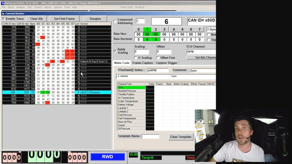
| 20:20 | What we've got at the moment is the CAN decoder up and visible and at the moment I've just got the car switched off so we don't really have anything happening here. |
| 20:32 | Let's just have a look at what we actually have available. |
| 20:35 | So you can see on the left hand side, I'll apologise here you'll just have to be looking at my cursor, I can't use my usual highlight device on our dyno. |
| 20:46 | We have our CAN ID represented in both hexadecimal as well as decimal values. |
| 20:52 | So this takes any possible confusion out of this, we know exactly what the CAN address is in both aspects. |
| 21:00 | Then we have the data represented by our 8 bytes. |
| 21:04 | So byte 0 through to byte 7, you'll see on the right hand side, the Mainline dyno will already identify some devices so it's set down here, this particular address is usually where we would see a Haltech input/output expansion module and likewise this address here is often used by a Life ECU or a Racepak however that's not really too relevant right now. |
| 21:30 | So let's just turn the car on, I'm not going to start it, and we'll just see what we get. |
| 21:35 | Now straight away, this is one of the advantages here with the way the CAN decoder works in the Mainline. |
| 21:43 | It straight away highlights in red any messages or any data that is changing and this makes it really easy when we do something like unplug the intake air temperature sensor or we unplug the engine coolant temperature sensor, it makes it very quick and easy to focus on exactly where that change was visible. |
| 22:05 | So to give you a quick example of that, what I'm going to do now is I'll just move the throttle from closed through to wide open and back and watch while I do this, you'll be able to see a whole bunch of data while I'm doing that changes, we can see a whole lot of those little boxes go red, representing the fact that something has changed. |
| 22:27 | Now of course I only moved the throttle there and we saw quite a lot of data changing and again, this can be reason for concern when you're just getting started, why did so much data change? And it's not uncommon to see the same piece of data being represented on more than one ID, it may be represented in a slightly different format and be used for different devices so that's important to understand. |
| 22:54 | Let's have a look now at how we can decode some of this data and we will start seeing as I just pushed my foot on the throttle, with the throttle position sensor. |
| 23:05 | So looking back at our raw data, I'm just going to move the throttle again, we can see that we've got some data changing, particularly around this area here which is CAN ID address 23D and 23E. |
| 23:20 | And what we're going to do, because I've obviously already done this pre webinar is we're going to move reasonably quickly and highlight exactly what's going on here. |
| 23:30 | So in this particular instance, I've highlighted that the actual data that we're interested in is coming through on that CAN ID 23D hexadecimal and the actual piece of data that I'm interested in is being sent, just going to change this here, we only really want to look at one byte of data at the moment, it's being sent via 1 byte and it's being sent on this byte 1 in our data pack. |
| 24:01 | So now if I move my throttle we can see that data moving and the way the Mainline dyno works, the CAN decoder works is we see the information being presented here at the top, we see we've got CAN ID X23D and this is our raw value in decimal being represented here and if we look here this is the ID, the byte we've got highlighted, we've got our raw hexadecimal value and then our raw decimal value, I'll just move my throttle again and we can see that changing. |
| 24:38 | OK so the important point here is we're going between, at the moment my throttle's closed, we've got a value of 0, if I go all the way to full throttle, we're getting to 255 or FF so that's the maximum value remember that can be sent via a single byte on the CAN bus. |
| 25:00 | So now we need to figure out a way of representing that particular data in a way that makes sense, obviously we don't want to represent our throttle position as 0-255, we'd much prefer to represent that as 0-100. |
| 25:17 | Now this is actually a relatively straightforward parameter to decode, let's just have a look at how we can go about it. |
| 25:28 | So you've got a better way of understanding it. |
| 25:31 | Let's just get this up. |
| 25:33 | OK so if we can go to my laptop screen at the moment and what I've done is I've just gone through and this is my usual technique, this would be how I would do engine coolant temperature for example and I've plotted on the left hand side, the raw decimal values as well as the actual throttle position. |
| 25:53 | So all I'm doing here, I would be either moving my throttle and looking at the scan tool. |
| 25:58 | Obviously with our Link G4+, we can go through and physically look at the throttle position that is being transmitted through the CAN bus and I've just simply gone through and done this at 0, 20, 40, 60, 80 and 100%. |
| 26:15 | Now again this is a linear relationship so I didn't really need to do that, I could have just done simply 0 and 100. |
| 26:22 | And then I've plotted that here on the right hand side in a chart and I've added a trend line and I've then added a formula for that trend line so this just gives us a formula so on a more complex parameter that we've be looking at, we'd end up often with a slope and offset so we can use that data for the equation that we're going to use to convert between the raw value and our actual throttle position. |
| 26:55 | So just give me one second and I'll get myself set up here. |
| 26:58 | So if we end up with a value here of 255 at 100% throttle, what we need to do is divide the finished, the raw decimal value by 2.5. |
| 27:19 | So let's do that now, what we've got here is some scaling data and we can basically change the representation from our raw data into what we actually want to view. |
| 27:35 | So again if I go at the moment between 0 and 100% throttle, we can see this box up here is showing the same as our raw decimal so this is the raw value coming through because at the moment we're not applying any scaling. |
| 27:49 | So if I now add a scaler of 2.55 and we divide by that, we can see that now as I move my throttle between 0 and 100, we see that we've now got something sensible, we're now moving between 0 and 100%. |
| 28:08 | So all we're doing is applying a multiplier, in this case this is a really simple situation because we've got no offset, all we're doing is using a multiplier or a divisor in order to change the data into what actually need to do so it's just simply moving between that raw value, 255 and the actual value we want to see on our screen. |
| 28:33 | Now I'll also just mention that the way the scaling is applied here on the Mainline dyno might not quite be the same as every device so for example here, I can enter a divisor, I can divide by 2.55. |
| 28:52 | Now for example on a MoTeC dash, we wouldn't be able to enter a value of 2.55, the MoTeC dash works in a slightly different way, it uses a multiplier and a divisor and an offset so let's just jump back to my laptop screen and we can see, if we look at our transmitted channels and we look at engine RPM for example, we can see the multiplier, the divisor and the adder, so these 3 aspects here are used in the MoTeC dash to make that same conversion from our raw value to the actual value or data that we really want to see. |
| 29:37 | So the process there we're going through is simply to look at the raw data and plot that against the actual values from either our ECU or our scan tool, the real values that we want to represent and then simply work out a conversion factor to get us from one to the other. |
| 29:56 | OK so let's move on and we're going to have a look at a couple of other aspects. |
| 30:01 | So the next one we're going to look at is our engine RPM. |
| 30:05 | So let's get our engine running and we'll see what data we've got once our engine is up and running, so we'll jump back to our dyno now, start the engine. |
| 30:15 | OK so straight away we can see we've now got quite a lot more data going on, we've got a few more boxes changing and we need to again go through the same process of figuring out exactly where abouts in the messages our engine RPM exists. |
| 30:33 | Now in this particular example, again I've already gone through this process and done a little bit of the hard work for us and the engine RPM is also being transmitted on this hexadecimal 23D ID. |
| 30:49 | So we need to find out where that particular information is and what I'm going to do is I'll just look at the moment, we've got the engine obviously idling and we're looking at what's changing across the bytes on this data. |
| 31:03 | We can see that at the moment our byte 3 is moving around, occasionally we're seeing some changes in byte 2 as well as byte 5. |
| 31:12 | What I'm going to do is I'll just bring the throttle up a little bit and we'll see what changes. |
| 31:18 | We can see quite a significant change in this data on byte 3 here. |
| 31:23 | And as I bring the RPM up further we'll also see that we saw a change in byte 4 as well. |
| 31:35 | Now I'm already expecting that a piece of data such as engine RPM is going to be transmitted over 2 bytes, we're not going to get good enough resolution if we want to send that over a single byte so I'm already expecting that it will be sent over 2 bytes and what I'm going to do here is just select that, so we're looking at a 2 byte message and I'll just get rid of the scaling that we had just looked at for our throttle position because we're going to start again. |
| 32:06 | OK so now we're looking at the data being sent between bytes 3 and 4. |
| 32:11 | One other aspect that I'll just touch on here is that there are 2 ways that we can represent data if we're looking at the data across 2 bytes like this, we can represent the data with the most significant bit first or the most significant bit last so, this is also known as big endian and little endian and essentially what it does is it defines which byte our most significant piece of the data is. |
| 32:44 | So let's say for example we wanted to send the decimal value 1, 2, 3 across. |
| 32:50 | Now if we sent that data and it was being sent in most significant byte first or big endian then we would read that data the same way, 1, 2, 3. |
| 33:02 | The opposite would be true if we were sending it in what's known as little endian or least significant byte first and it would be represented as 3, 2, 1. |
| 33:13 | I know it's confusing but it's important to understand because in this case the information for engine RPM is being sent through with the least significant data first. |
| 33:27 | So this can be changed here in our Mainline software by clicking the little Motorola icon here. |
| 33:36 | So this is again one of the areas where terminology differs depending on what software you're working on so some manufacturers will represent it as big endian or little endian, others will represent it as LSB for least significant byte or MSB and in this case we're using the terminology Motorola. |
| 33:59 | OK so now we've got our, oh I'll just unclick that again, so now we've got our data, we know this is where our engine RPM is, we need to convert this into something useful. |
| 34:11 | So at the moment I'm sitting at idle and again what I'm doing here is I'm using my ECU data or my scan tool to see what the actual engine RPM is. |
| 34:24 | We have a way of simulating this and bringing up a fixed accurate engine RPM value and that would be another valuable way of getting this data across so we know exactly what's going on. |
| 34:36 | So if I just bring the engine RPM up, we can see that as I raise my throttle, the raw value on our CAN decoder does increase but at idle right now I'm sitting at about 830 RPM. |
| 34:51 | We can see that the value here is sitting at about 260, 270. |
| 34:58 | Just to show you the difference between the most significant byte first and least significant byte first, if I click the Motorola tick box there, and this is representing that data with the most significant byte first, we can see that it's just basically garbage, it's just jumping around all over the place and we can't really make much sense of it. |
| 35:21 | So that's a really good indication of when we're first searching for the data that something, we've probably got that around the wrong way or we're alternatively looking in the wrong place for the data. |
| 35:34 | OK so what we want to do is now convert this into something realistic. |
| 35:40 | Now in this case again I've done this before, the process is exactly the same but we find that a multiplier of about 3.1, I think it's 3.15 actually, gives us the correct value. |
| 35:53 | So now we can see we're sitting at an RPM of 820, 830, I'll just bring the RPM up. |
| 35:59 | And we can see that the RPM follows. |
| 36:03 | So again the process here is simply the same, we're looking at our raw values versus our actual data from either our ECU or scan tool and we're determining a conversion factor or a scaling that's going to get us from that raw hexadecimal value through to the actual data that we want to be able to see. |
| 36:28 | OK we're going to look at two more things, we're going to look now at engine coolant temperature and there's quite a neat little way that I can go through this and show you very quickly and easily how I've done that in the G4+ so let's do that now. |
| 36:44 | So what I'm going to do is just go, if we can jump into my laptop software, I'll just go online with our G4+. |
| 36:51 | Now rather than using a resistor bridge and adjusting the resistance across the engine coolant temperature sensor and looking at how that changes, in the G4+, all I'm going to do is put the engine coolant temperature sensor into fault and then I can simply vary our error value here really quickly and easily to adjust the actual temperature that is being sent via CAN. |
| 37:18 | So let's do that now, all I'm going to do is set our high fail at 0.1. |
| 37:24 | Straight away we can see that our engine coolant temperature sits on our default value. |
| 37:28 | OK so now the process is the same so hopefully, what we'll do actually, we'll just jump back to viewing the dyno screen. |
| 37:37 | And what I'm going to do is I'm going to just change our engine coolant temperature data from 100 to 0 and I'm going to press enter now and look at what changes. |
| 37:50 | Now again there was a little bit of data changed there. |
| 37:54 | It is a bit of a case of deducing exactly which piece of data we're interested in and in this case again I've done this already, I know that the piece of data that I'm interested in is coming through again on that same CAN address, 23D hexadecimal and it's being represented by byte 7. |
| 38:17 | OK so we know what's going on now, we've got that data coming through on byte 7. |
| 38:23 | What I'm going to do is we'll just clear our scaling so we're not applying that so we'll set that to 1. |
| 38:30 | Alternatively I can just click the apply scaling button, that turns that off. |
| 38:33 | So right now we've got a value of 0°C being sent through via CAN. |
| 38:46 | We can see that that equates to a raw value of 50. |
| 38:51 | So we've got some work to do there, doesn't quite line up. |
| 38:55 | Let's now change this to 100°. |
| 39:00 | We can see that with a value of 100°, our raw value jumps up to 150. |
| 39:06 | And if we go to a value of -50°. |
| 39:11 | We can see that our raw value now goes to 50. |
| 39:17 | Now I wanted to demonstrate this particular parameter because this is quite common when we're sending temperatures via CAN. |
| 39:26 | Rather than trying to represent assigned values, so sending through perhaps -10 or -5° which we could quite easily get with both water temperature and intake air temperature and I'm talking °C here just to be clear. |
| 39:43 | Rather than doing this, what we end up doing is offsetting the data that we send through and then in the end when we're decoding it, we remove that offset. |
| 39:54 | So in this case we can see that essentially the entire data is all offset by 50°. |
| 40:00 | So it's relatively straightforward. |
| 40:03 | All we're going to do here is select our offset and we're going to enter -50 and straight away we can see that now our engine coolant temperature lines up. |
| 40:13 | We've got 100° and our ECU is also showing a value of 100°. |
| 40:20 | I'm going to enter a value of 0 on the laptop, straight away we see that changes to 0. |
| 40:25 | But the important thing here is now if I enter a value of -20°, we can now represent that because the entire data had originally been offset when it was transmitted by a positive value of 50° so that would essentially let us display down to -50°. |
| 40:45 | OK one more piece of data that we're going to look at and that is how we can decode wheel speeds. |
| 40:55 | And for this particular example I'm going to use the graphing method that I showed you using Excel again. |
| 41:02 | OK so what we're going to do is I'll just put the car into first gear and we're going to go through that same process of straight away looking on the dyno. |
| 41:10 | So we'll look at the dyno screen while I do this, we want to straight away look and see where the data changes so I'll just change this also back to 2 bytes. |
| 41:21 | OK, that's great. |
| 41:27 | I don't really know what's happened there, just decided to crash on me. |
| 41:32 | Perfect. |
| 41:37 | Technology, no matter how hard we try, it's still not rock solid, just give me a second and we'll just get this back up and running now, won't take a second. |
| 41:47 | We have had some issues with the CAN to USB adaptors and they do seem occasionally to be a little bit hit and miss so that's probably what happened there. |
| 42:01 | I'll just click on set up data devices and we will go back into, OK what have I got here? Bear with me for a second. |
| 42:14 | What I have to do here is just set the CAN bus baud rate or speed that it's transmitting or receiving on to match what we're actually doing, otherwise if the speed is incorrect we're going to have a whole bunch of problems where the whole CAN bus won't be able to communicate. |
| 42:32 | OK we're back up and running now so I apologise for that. |
| 42:37 | We'll just put the car in first gear. |
| 42:40 | So I'm going to let... |
| 42:51 | Just bear with me I'll just reset everything. |
| 42:55 | I think that's ended up just crashing everything, there we go. |
| 43:00 | Right, that was exactly what I was talking about where the baud rate initially or the communication speed with the CAN bus was incorrectly set and that gave us a whole bunch of nothing with our data so we're back up and running, this is where we were. |
| 43:16 | Apologies for that. |
| 43:19 | Right we're in first gear now and I'm just going to let my foot off the clutch and we're going to look at where, what sort of data we see change. |
| 43:28 | Now obviously I'm only going to see two wheel speeds change here because we're only going to be turning the rear wheels. |
| 43:35 | Just put my foot back on the clutch and what we're looking at here is we want to highlight this area. |
| 43:41 | So I'm on the clutch at the moment, the car isn't moving, just going to come slowly off the clutch and look what happens as the wheels start to turn. |
| 43:51 | We see data across bytes 0, 1, 2 and 3. |
| 43:57 | So I'm expecting this to represent my left and right rear wheel speeds and again I'm already expecting this data to be sent via 2 bytes. |
| 44:10 | So what we want to do is look at how that data relates to our actual wheel speed. |
| 44:17 | So again if I just put the car in first gear now, I'll just come off the clutch, we'll just go into 2nd and I'm bringing the speed up to, we're sitting at about 20 km/h right now and we can see our raw value here is So before we came on for this particular webinar, I've already gone through and plotted this and we'll just go to my laptop screen right now. |
| 44:45 | And we can see on the left hand side we've got our raw decimal values as well as our actual speed and in this case, again I was simply matching this against the speed being read by the Link G4+ ECU, of course we could use a scan tool if you want, you could also trust the speedometer on the car as well. |
| 45:07 | So what I've done is I've got that data and then I have plotted that data on a graph here. |
| 45:14 | Now obviously for a quick test there, there's a little bit of inaccuracy potentially in that data and what I've done is I've added a trend line through there, it's quite difficult to do this accurately, simply because we're looking at trying to hold the road speed very accurate to within perhaps 0.1 km/h and then look at what's going on with our raw values from the CAN bus at exactly that same point. |
| 45:43 | So of course it's likely that we're going to get some inaccuracies creep in there. |
| 45:47 | So what I've done is I've added a trend line there and we've looked at a linear trend line and again because there were some inaccurate points in my data, on the right hand side here, I've also selected to set the intercept to 0 so what that basically means is my trend line is being forced to run through the 0 point. |
| 46:09 | We know we have no offset here because our raw value is 0 when our road speed is 0 also. |
| 46:16 | And then I've said can we display the equation for the slope of this graph which in this case, this slope is 0.0051 so what we can do now is apply that same multiplier or scaler to our raw data. |
| 46:33 | And again I'm just going to 0051, I'm going to set the scaler to the same as what I've got on my trend line there. |
| 46:45 | Right now we'll put the car back in first gear, I'm just going to let my foot off the clutch, sorry I should have said we're back on our dyno screen now, this has been a little bit messy because we're swapping between the dyno screen and my laptop screen. |
| 47:00 | And you can see now we've got some data that's pretty representative, I'm sitting now in second gear at about 19 or 20 km/h and you can see that's exactly what we've got coming through on the dyno screen. |
| 47:14 | So hopefully that's given you a little bit of insight into what admittedly has been some reasonably basic CAN bus decoding. |
| 47:24 | Now we're going to move into some questions and answers really shortly so this is a perfect time if you do have some questions to ask those now in the chat box and I'll be able to address those very shortly. |
| 47:36 | Hopefully I'll be able to answer them for you. |
| 47:39 | So really the point here I guess is the CAN bus isn't something that you should be scared of, it requires a certain about of understanding of the basics, the fundamentals behind it but when you understand those fundamentals, it's actually not that scary and the principles, the procedure that we go through for finding data on the CAN bus and decoding it is actually relatively straightforward. |
| 48:06 | All we're really doing is making a change to whatever parameter we're interested in and we're looking at how that, what changes on the CAN bus so that's going to let us, first of all zero in on what address that data is being sent on. |
| 48:22 | Once we understand where abouts the data is on the CAN bus then we can go through the process of coming up with a scaling that's going to convert between that raw value and something that's actually useful for us. |
| 48:38 | There's also two aspects to this, we can use this technique here to decode a factory CAN bus and read it into, for the likes of a MoTeC dash logger for example. |
| 48:53 | We can also use this technique to decode factory CAN messages and then replicate these messages using an aftermarket ECU or a dash and really the reason I went through this process on our 350z is that one of the ECUs that we use regularly is the Haltech Elite 2500 ECU. |
| 49:17 | Now they don't have a CAN template to replicate the factory CAN messaging for the 350Z system so when we run this ECU, we end up wtih a dash that doesn't work, we end up with the engine fans running all of the time because the engine fans are traditionally controlled via CAN messages. |
| 49:42 | Not particularly a big problem for us but it's also not ideal so what I did was went through and reverse engineered or decoded those particular parameters that I was interested in and once I decoded those particular parameters, then I actually used the MoTeC C125 dash to then transmit those messages back out. |
| 50:05 | So this ended up giving us a rev counter on the dash, the factory dash that works. |
| 50:10 | Obviously a little bit irrelevant when we've got a MoTeC C125 sitting in front of it anyway. |
| 50:17 | We've also got the coolant temperature working on the dash which again, replicated on the MoTeC C125 but we do now have a fan control that's working correctly as the factory intended with both a high and low speed fan control. |
| 50:32 | Alright, looks like we've got no questions on that which I must admit I'm a little surprised at. |
| 50:39 | I'm sure that you guys would have had some questions but maybe I've just done such a good job of explaining it that all of your questions have been answered. |
| 50:48 | I hope that's the case and I hope that it has gone some way to clearing up the CAN bus communications and how to decode them. |
| 50:57 | As usual, if you do have any further questions, please ask them in the forum and I'll be happy to answer them there. |
| 51:04 | Thanks for joining us and I look forward to seeing you all next week. |


