135 | Introduction to VNT Turbo Boost Control - Variable Nozzle Turbochargers
Summary
Variable Nozzle Turbochargers (VNT) are a common option in the diesel tuning world, and while they offer some impressive advantages compared to conventional turbochargers, they also have some unique considerations when it comes to control strategies. in this webinar we’ll cover the control strategies and tuning of the VNT boost control system on a Toyota Hilux Diesel engine using a MoTeC M150 ECU.
| 00:00 | Hi guys, Andre from High Performance Academy. |
| 00:02 | Welcome to this webinar where we're going to be looking in a little bit more detail at how a VNT, or variable nozzle turbocharger works. |
| 00:11 | Now while they are more common in the common rail with diesel tuning world, they're certainly not exclusive to diesel engines, and it is a technology that you may come across that requires a little bit of an adaption of the way we'd normally control boost pressure in a turbocharged vehicle. |
| 00:31 | There are also some knock-on effects for how the VNT turbocharger actually affects airflow through the engine, or in other words, the volumetric efficiency of the engine, and these are some of the topics that we're going to be looking at in this webinar. |
| 00:48 | As usual we will have a section for questions and answers at the end of the webinar, so if there's anything that I discuss that you would like me to delve into in more detail, please ask those in the chat and I'll be happy to deal with those at the end of the webinar. |
| 01:02 | For this particular webinar we are going to be presenting this on a Toyota D-4D 1KD turbo diesel engine, and this is going to be running on the MoTeC M1 diesel beta platform, so really the specifics of that platform aren't really too important. |
| 01:23 | We're going to go through the aspects that relate to the turbo control, and really that's all we need to know about here. |
| 01:30 | It's not going to actually really affect us too much that this is on a diesel engine. |
| 01:37 | So let's start with what is a VNT turbo? As I mentioned, it stands for variable nozzle turbocharger, they are also referred to as a variable-geometry turbochargers. |
| 01:51 | There's a few different variants of name, but in essence what they are is a turbocharger with a range of little vanes built into the exhaust housing that allows the effective A:R of the housing to be altered on the fly, while the engine's operating. |
| 02:12 | We've got a picture here that I've just managed to find from Volvo, so we'll jump across to my laptop screen, I'll just give you a bit of a look at how that works. |
| 02:22 | So the part that is specific to the VNT turbocharger is the way the exhaust housing is constructed. |
| 02:31 | So the actual turbocharger itself is still, for most part, a conventional turbocharger, but what we can see here is these little vanes that rotate in the exhaust housing, and by opening or closing these vanes we can affect the, essentially affect the A:R of the exhaust housing supply, the turbocharger with differing amounts of exhaust gas energy, and what this allows us to do is with a VNT turbocharger, we essentially, by moving these vanes, can make the turbocharger act like a small turbocharger with a very tight exhaust housing that's going to provide good low-RPM performance, a low boost threshold, but at high-RPM we can then open those vanes, which is going to mean that the exhaust backpressure isn't going to become super-restrictive. |
| 03:23 | So we've got the two openings, or two positions for these vanes are shown in this drawing. |
| 03:30 | At the top here, you can see this is the narrow vane opening so this is what's used for low-RPM to provide quick, fast response to our turbocharger, but of course, if we were to hold the turbine housing in this position at very high-RPM, well we're going to end up with a situation where the exhaust backpressure becomes excessive and that's going to limit performance. |
| 03:56 | So at high-RPM, once the turbocharger is spooled, we move the vanes and open them, this becomes less restrictive, this acts a little bit more like a larger A:R exhaust housing and hence we end up controlling our boost pressure and we also don't end up with excessive backpressure. |
| 04:18 | So the VNT turbocharger, typically we don't actually need a wastegate with this type of turbocharger, so the way we actually control boost pressure is by simply opening or closing the vanes in the exhaust housing of the turbocharger. |
| 04:33 | So I've shown on that particular picture there from Volvo, the vanes in two positions, but of course we don't just have two positions. |
| 04:42 | The vanes can be varied infinitely between fully open and fully closed, and this gives a lot of control over the airflow to the turbocharger, the exhaust flow to the turbocharger, and hence the response of the turbocharger. |
| 04:58 | So with the VNT control, the VNT system can either be pneumatically, or electronically controlled. |
| 05:06 | In the case of our Toyota turbocharger it uses a servo motor for electronic control of the VNT system, and that also incorporates a position sensor, so there's some feedback there. |
| 05:23 | Now what we'll do here is just have a quick look in the MoTeC software, and see how that all works. |
| 05:32 | So if we can jump across to my laptop screen, what we've got here is a setup for, whoops, a setup for our boost servo. |
| 05:41 | So essentially there is a position sensor, we'll just scroll down so we can see that. |
| 05:46 | We've got a position sensor setup, at the moment this is coming into Analog Voltage Input 8, so this is a simple zero to five volt sensor that tells the ECU what the position of the VNT vanes are between completely open and completely closed. |
| 06:05 | Now if we move back up, once we've got that system in place, the M1 ECU uses a linearization, so what it does is it converts the VNT vane position into a duty cycle between zero to 100% that's used for the actual boost control system. |
| 06:25 | So once it's gone through this linearization, essentially everything kind of works pretty similar to a conventional wastegate solenoid, where the ECU is just supplying a duty cycle to the solenoid between zero and 100%, so this is how it's controlled in the M1. |
| 06:43 | It converts the duty cycle into a VNT, or boost servo position via this linearization. |
| 06:52 | So just to have a look at this here, we can see that on the axis we have two points, we've got zero and 100%, so these are our boost control duty cycles, and those are being converted into a percentage of the VNT travel. |
| 07:10 | So with a duty cycle of 100%, you can see we've got a value there of 45%, so this tends to have the VNT system quite closed. |
| 07:23 | 45% is not as closed, not as closed as it can go, and this is one area where we do need to be a little bit careful, we can actually close up the VNT system so far that it essentially chokes the exhaust flow out of the engine, and in some instances we can actually end up having the engine stall, because essentially we've completely blocked the exhaust system. |
| 07:46 | So in order to get these values, what we actually did was started by logging the factory position from Toyota, so we saw what the minimum position and the maximum position that Toyota were using to actuate the VNT system, and replicated those values. |
| 08:05 | What I'm going to do is I'll just start the car, and I just wanna show you the effect of the, so at the moment you can see we've got a little yellow cursor, yellow pointer showing that currently our duty cycle being fed out of the boost control subsystem in the M1 is 100%, so in the moment we haven't reached the boost target that we've got at this point, so the ECU, just like you'd do with a conventional wastegate system, is holding the wastegate completely closed in order to build boost. |
| 08:37 | Obviously I'm only sitting at idle here at the moment, so we can see that that translates to a position of 45%, that's what we've got in our linearization table, and if we look down at our sensor position, we can see that for the most part, while it is moving around a little bit, we are sitting at about 45%. |
| 08:58 | Now the important point to note here, this is just a quick demonstration of how much effect this has on the exhaust backpressure in the engine. |
| 09:06 | We have a logged parameter here which is exhaust pressure, and you can see at the moment we're sitting at around about 11 or 12 kPa, just sitting here at idle. |
| 09:17 | What I'm going to do is just drop this down from 45% to 29. |
| 09:23 | So what we've done there is we've just closed the VNT nozzle tighter. |
| 09:30 | Now the effect of that's instantly noticeable, you can see that our exhaust backpressure has jumped up, we're now sitting, for the most part, somewhere around about 100 kPa, and the point where I closed that VNT nozzle is right here, so we can see that really sharp step in our VNT, in our exhaust backpressure that's corresponded to that VNT position change. |
| 09:53 | So this is one aspect that is important to keep an eye on here, and this is why we've started by working backwards from Toyota's default values, or minimum and maximum values. |
| 10:06 | The reason I say this is while closing our wastegate, our VNT nozzle down tighter like this, it is going to help our boost response. |
| 10:16 | What it does is it actually tends to create so much exhaust backpressure that it strangles the engine, and what this is going to do is mean that, particularly in cruise, a cruise situation, we're actually strangling the engine and that's going to be counter-productive for our engine performance, and definitely in terms of our engine economy, so we'll just take this back up to our base value. |
| 10:42 | You can see as soon as I do that, I take it to 45%, our exhaust backpressure drops back, and what won't be audible to you is the whole engine note changes. |
| 10:52 | As soon as I go to 45 kPa, ah sorry, from 45 to 29% there on our VNT position, what we notice is that the engine sounds strangled, it drops its engine note slightly, and we also end up providing more energy to the turbocharger. |
| 11:11 | If we had a turbo speed sensor we would be able to see that aspect as well, but I can actually hear the turbocharger starts to produce a very slight whistle as well, so this is how the M1 system controls the VNT system. |
| 11:29 | Okay, so once we have that system setup, once we've got the VNT position sensor setup, in this case because it is electronically controlled and we've got the servo motor, this is using ah, a bridge output the same way as the M1 drives a drive-by-wire throttle motor, once we've got all of that setup then the tuning sort of becomes very similar to what we would use for a conventional pneumatic external wastegate, or internal wastegate, and we'll have a look at a demonstration of the tuning process pretty shortly. |
| 12:08 | Now there is a really key point here though to keep in mind, when we are tuning with a VNT turbocharger, when we change the VNT position, as we've seen there we've got a really large effect on our exhaust backpressure, and what this tends to do is in turn, have a knock-on effect to the engine's volumetric efficiency, so one of the aspects here, and this is one of the reasons why the M1 package that we're using uses mass airflow instead of a conventional volumetric efficiency system that's so common now in aftermarket ECUs, if we are using a VE, or speed density system for our tuning, anytime we make changes to the VNT position, that's going to have a corresponding knock-on effect to the engine's volumetric efficiency, so you get into a position where you're sort of chasing your tail every time you make a change to the VNT turbocharger position. |
| 13:08 | This in turn effects the volumetric efficiency of the engine, which means that you may need to then go and make changes to your volumetric efficiency table in order to get your air/fuel ratio back on track. |
| 13:21 | With a mass airflow system on the other hand, because the ECU is being directly told the mass of air entering the engine, this understandably will vary with the exhaust backpressure, our VNT position, so essentially everything still tracks really nicely and our fueling will be easier to control. |
| 13:43 | So that's just one aspect to consider there. |
| 13:46 | I wouldn't say that it is impossible to tune a VNT turbocharger using a speed density system, but it is something that you do need to understand if you are making large changes to the VNT turbo position, it will have an effect on the engine's volumetric efficiency. |
| 14:05 | Okay, so what we'll do now is we'll go through a quick demonstration of the tuning process here using our Toyota 1KD engine on the Mainline dyno, and we'll see how everything actually works. |
| 14:18 | We'll just get the engine up and running again and we'll just jump into our boost control settings and we'll have a look through and see how everything works here. |
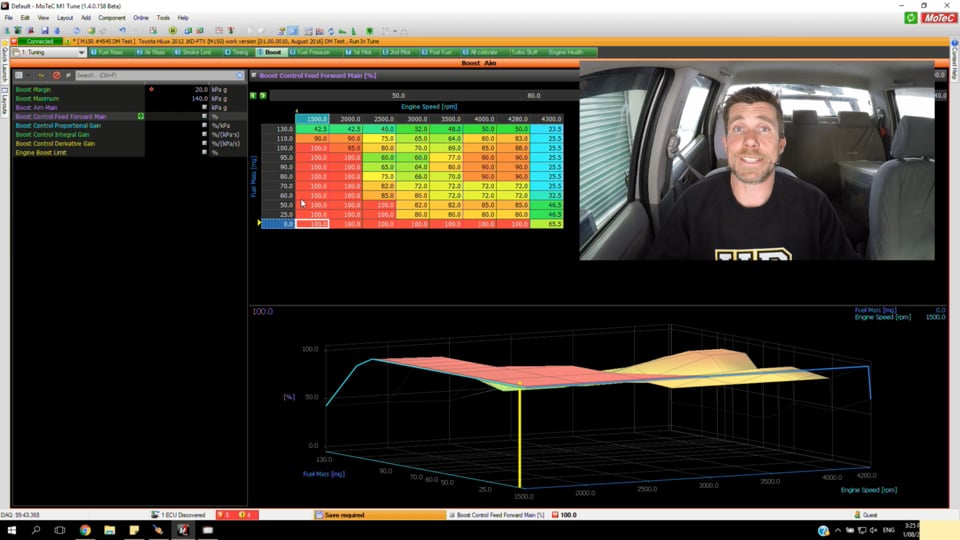
| 14:32 | Okay, so the boost control, as I've said, really looks, for the most part, quite similar to a conventional wastegate, pneumatic-style wastegate system, and we've got here to start with, our boost aim table. |
| 14:45 | So these are our boost targets, this is our desired boost target. |
| 14:51 | You can see here an aspect that is unique to the diesel engine, is that the load axis for this table is fuel mass, so we don't need to be too worried about that, you can see that I've actually got a really simple table setup here, and I am targeting a boost pressure of 120 kPa. |
| 15:10 | This is gauge pressure as well, the MoTeC boost control system in the M1 uses gauge pressure as its target, so gauge pressure is simply the difference between the inlet manifold pressure and the barometric air pressure. |
| 15:25 | Right now we are quite low in our barometric air pressure, we sit at around about 95 to 97 kPa here in Queenstown, so this just is something we need to keep in mind, for those who are more used to viewing absolute pressure numbers for your boost pressure. |
| 15:43 | So 120 kPa, somewhere around about, sort of 18 odd PSI is our boost target. |
| 15:50 | The feed forward table is where the ECU is going to take its base values from for the VNT position, so again, this looks, on the face of it, very similar to a conventional boost control duty cycle map. |
| 16:09 | We've got a four-dimensional setup here, so we can see we've got an axis of our boost aim, so we can set our VNT nozzle position relative to fuel mass, engine RPM, and also boost target. |
| 16:24 | For us at the moment, because as I've just looked at our boost target is 120 kPa everywhere, we can focus solely on the 120 kPa map and we can ignore, for the time being, our other boost aim values and just concentrate on this as a single three-dimensional table. |
| 16:45 | Again here we have our fuel mass as a load point, I'll just briefly touch on this, just so it isn't confusing. |
| 16:52 | With a diesel engine, the more fuel we add, essentially the more exhaust gas flow is supplied to the turbocharger, so unlike a petrol engine, with a diesel engine, as we vary the amount of fuel that we're supplying to the engine, this can also affect our ultimate boost pressure. |
| 17:13 | So unlike a petrol engine we've got this other dimension, other parameter here that's also affecting our tuning. |
| 17:19 | So this really isn't too much different though to a petrol engine, where we would use perhaps a load axis of throttle position, or something similar, so this just adds one more dimension that we need to consider in a diesel engine. |
| 17:35 | Okay, so remember here that what the ECU is doing is taking the value from this particular table, our duty cycle table that's going to vary between zero and 100%, and then it's converting that through the linearization table that we just looked at over here, and it's converting that into a position for our boost servo, our VNT control servo motor, and the servo motor is achieving that by using a PID control algorithm. |
| 18:05 | It's looking at the target, and then it is looking at the measured position, and it's making adjustments to the servo in order to try and achieve our target. |
| 18:17 | So once this is all setup and it's controlling nicely, we can really kind of forget about that and we're going to focus all our efforts here in our boost control map and our feed forward map. |
| 18:29 | So what we'll do now is we'll just get our car up and running on the dyno. |
| 18:34 | Let's just jump across to the dyno, we'll watch the dyno during this ramp run. |
| 18:39 | Remember we've got a target of 120 kPa, I've put a reference line here on the dyno at 18 PSI, just so we can see how close we are getting to that. |
| 18:50 | We'll just get up and running in fourth gear, we'll do the run on the dyno, we'll have a look at the data on the dyno, and then we'll also be recording this in our time graph here on the M1 ECU, and we'll have a look at how that works once we've looked at the actual live data, live run on the dyno. |
| 19:12 | All right, I'll just let everything settle for a few seconds, let our boost just come up to a control point, just build a little bit of exhaust temperature so that we get some reasonably consistent results. |
| 19:26 | Let's get our run underway now. |
| 19:49 | Okay, so we can see there we've ended up with 123.6 kilowatts, 165.8 horsepower at the rear wheels. |
| 20:00 | Really the power aspect wasn't too critical to this demonstration, we're really looking at our boost control more than anything, and we can see there we've got a lovely flat boost line, pretty close to our target. |
| 20:13 | Let's just actually look at the boost, pretty close to our target there at 18 PSI. |
| 20:18 | Now let's just jump back across to our laptop screen and we'll have a look at exactly what happened during that run. |
| 20:26 | What I'll do is I'll just fullscreen our time graph here. |
| 20:29 | So the first place to look here is our boost aim versus our boost pressure, so the boost aim, simply the value coming from our boost aim table, you remember that was 120 kPa. |
| 20:41 | The green line is our measured boost pressure and gauge values, so we can see that we've come up and we've made full boost a little bit below 2,000 RPM, and for the most part here we are within, probably one and a half or two kPa of our target. |
| 21:03 | What we can see also though is what the boost control system is actually doing here. |
| 21:08 | I'll just get rid of that channel that we're not really that interested in. |
| 21:14 | We can see what our boost control system is doing, and this is how we go about fine-tuning the feed forward table, or our boost control table. |
| 21:23 | So in this particular group here we've got a few aspects that are important here. |
| 21:30 | We've got, first of all in purple, we've got our boost control feed forward. |
| 21:36 | So this is the value that's coming from our feed forward table, that was the table we looked at, so this is where we're putting our base duty cycle values in. |
| 21:44 | So this is, essentially you can think of as our open loop table, these are the base duty cycles that are going to go through that linearization table and become a position for the VNT turbocharger nozzle, and what we want to do is have a look at how close, well what the actual final value that's being sent to our boost control system was, and that's our yellow line which we can see here. |
| 22:10 | So the yellow line is the actual final value that's being sent to the boost servo control system. |
| 22:16 | So this takes into account the PID control algorithm, or control setup of the boost control system, so anytime the boost isn't quite matching our desired target the M1 ECU will go through and make corrections to the final duty cycle being delivered in order to try and drive the boost towards that target. |
| 22:36 | So what we can see here is, in this particular point, 2,200 RPM, we have a feed forward value from our table of 81.9%. |
| 22:48 | Our boost is very slightly too low, we're at 118.8 kPa, our boost target is 120, so we can see what's happening down here with our three elements of our PID control. |
| 23:02 | We can log these and see what each of those is doing to the final value for our boost control system. |
| 23:08 | So at the moment we have 0.9% of proportional gain, or proportional values being added in. |
| 23:15 | We have 0.1 as an integral element, so that gives a total of 1% which we can see if we look up within the realms of the values we're looking at, essentially it's exactly what we've got, we've gone from 81.9% to a final value of 83%. |
| 23:32 | Now a way to use this data as well is we can setup our boost control and then if we find that the actual boost we're reading is on target, which essentially we've got there, we want to look and see what the final boost control value was, what the closed loop system has been doing in order to achieve the boost, and then if there's a difference between our feed forward value and our final boost control value, we can then go through and make adjustments to our feed forward table. |
| 24:06 | So to give you an example of that, what we can see here, at the later part of the dyno run, we can see that our boost's a little bit lower than our target, so 117.6 kPa versus 120. |
| 24:23 | Now what's happening here is the proportional and integral gains are driving the boost control system to try and fix that error. |
| 24:31 | You can see that at this point we're adding 2.3% from the proportional element, 1.7% from the integral element, and actually we're moving .1 of a percent thanks to the derivative element, so what that adds up to is over this area we can see that the yellow line is actually a little bit higher than our feed forward table values. |
| 24:52 | So we can see we've got a value of 77.4% from our table, our feed forward table, and the final value being delivered to the boost control system is, or the boost servo, is 81.3%. |
| 25:07 | So what we'll do here is make changes to that particular point in the table, I'll show you how we can do that. |
| 25:15 | If we, it's easiest if we make sure that we're making changes to one of the areas where we actually have a break point in our table, so in this case what I'm gonna do is I know that I have a break point in our feed forward table at three and a half thousand RPM, so we'll go down to the point in our table where we have three and a half thousand RPM, sorry in our time graph, three and a half thousand RPM, and we can see at this point the value in our table was 64.1%, the final value being delivered was 66.2%. |
| 25:48 | We also can see that we're still 1.1 kPa low, so we actually could go and add a little bit more to our table value than the 2% that is currently being added by the PID algorithm. |
| 26:03 | I'll just close down this time graph and we'll bring up our feed forward table a little bit larger. |
| 26:11 | What we can do here, if we are active at a particular point in the time graph, we can press space bar and it's going to take us to the exact point in the table that was being accessed during that run, so the exact point that was being accessed at that point in the time graph. |
| 26:28 | So we can see we're sitting at three and a half thousand RPM which you already knew, also the fuel mass at that point is 110 milligrams. |
| 26:36 | We can see we have a value there of 64% which we already know from our time graph. |
| 26:42 | Remember we had a 66% being sent out to the boost control system, we're still a little bit low, so what we can do there is just preempt that by taking it up to 67%, so this becomes an iterative process. |
| 26:56 | We can now go back to our time graph, I'll just open it up fullscreen again, and the next point that we had in our table was at 4,000 RPM, so I'm just going to move through to 4,000 RPM here, and we can see at this point we're now adding around about 4% to our feed forward value. |
| 27:18 | We're up to 86.8%, but again we can see that we're around about two and a half kPA lower than our target, so what we can do is again go back to our feed forward table, we can go to that particular point in our feed forward table and this time you can see we're actually starting, well you may not be able to see, it's a little bit hard to make out, but we're actually interpolating slightly between two rows in that table, we're interpolating between 100 and 110 milligrams of fuel. |
| 27:51 | What I'm going to do there is just highlight both of those cells, and if I just go back, I've actually completely forgot on what we were adding there. |
| 28:01 | We went up 4%, so what I'm going to do there is just add 5 to that particular site. |
| 28:09 | So this is the process we can go through in order to create the feed forward table based on the feedback that we're seeing in our time graph. |
| 28:19 | Of course to get to this point we do need to already have a PID control algorithm that's at least in the ballpark. |
| 28:27 | If our PID control algorithm is way off, we're going to get large swings and oscillations in our boost control duty cycle, and really we're not going to be able to get any useful data from this. |
| 28:38 | Just as we go through in our boost control tuning course, if you want more information on PID tuning, it's all contained in that course. |
| 28:47 | The best place to start is to actually disable the closed loop control system. |
| 28:52 | We can do that by zeroing out our P, our I and our derivative, D, gains that essentially makes the ECU act like an open loop control system, it's going to ignore any error, and then we can get our boost close to our target by just then tuning our feed forward table, and then we can re-enable our closed loop control. |
| 29:17 | What we'll do is, I'll just do one more run now with those changes made, and we'll see how that affects our boost control. |
| 29:25 | Now we'll move into some questions and answers really shortly, so if you do have anything that you would like me to discuss, please ask that in the chat now and I'll deal with that in a second. |
| 29:38 | So what I'll do here is I'll overlay our next run with the run that we've already got, and then we'll, again, analyze this in our time graph and see what the effect of those two changes we've just made have been. |
| 29:54 | Also once we're finished this run, I just want to also go over the exhaust pressure, exhaust backpressure and we'll see what that's actually done during a run as well. |
| 30:05 | All right, I'll just go through to full throttle and just allow the engine to settle for a few seconds, and once we've got a stable boost pressure, built some exhaust temperature, we'll get our run underway. |
| 30:23 | All right, let's see what we get this time. |
| 30:47 | Okay, so essentially exactly the same power there which is no big surprise, we're only really chasing differences of a couple of kPa. |
| 30:56 | We actually ended up with a slightly slower boost response there, probably just due to exhaust temperature differences between those two runs. |
| 31:07 | One of the things when we are tuning any turbocharged vehicle, whether it's a conventional wastegate system, or whether we've got a VNT turbocharger, the boost response and boost threshold of the turbocharger is very dependent on exhaust temperature, so if we do a run when everything's stone cold what we're going to find is that the boost threshold, the point where we actually reach full boost, tends to be quite a lot later in the rev range than if we do a couple of runs back-to-back. |
| 31:36 | We've got everything up to operating temperature, you will find that our turbocharger comes on boost much quicker. |
| 31:42 | Okay, so let's just jump across to our laptop screen, we'll just fullscreen this data and we can see that this time we've probably actually gone a little bit too far, but you know we've got, you've got to also appreciate, here we are really splitting hairs. |
| 31:59 | We've got boost control that, throughout this entire run, is within around about 1 kPa of our target, so it's pretty damn good. |
| 32:08 | This time we can see, if we look at our boost control percentage versus our feed forward table, they're all within around about 1%, so this is again, sort of indicative that our feed forward table, our base duty cycle table is pretty well setup and optimal, and regardless, again, whether we are using a conventional wastegate or whether we are using a VNT turbocharger, the closer that feed forward table is, the less work our closed loop control system is going to need to do, and the less our closed loop control system needs to do to correct error, the better our overall boost control is going to be. |
| 32:48 | Now we'll just come down as well and have a look here, I'll just change our scaling here so we can see what our exhaust pressure is doing. |
| 32:58 | We'll take that up to 300 kPa. |
| 33:02 | Now you need to appreciate here that we are dealing with an undamped exhaust manifold pressure sensor, so this is why we've got a lot of noise in the data here from our exhaust pressure. |
| 33:17 | I can't filter that within the time graph here on the M1 ECU live, we could filter that post the data being collected in MoTeC's i2 software, but I can't do that in real time, however you can sort of mentally also smooth this and essentially what we see is the exhaust pressure is still climbing quite sharply as we get to high-RPM, which is to be expected, still we have a relatively small turbocharger for the engine, and of course diesel engines are really not designed to rev particularly high. |
| 33:58 | They are designed for low-RPM torque, so even with the VNT turbocharger, the design and sizing of that VNT turbocharger is still skewed towards providing good low-RPM performance. |
| 34:11 | The important thing to note here though is in comparison to a fixed-geometry turbocharger, we have got the ability here to make full boost at a little under 2,000 RPM, or our 120 kPa of boost at a little under 2,000 RPM, yet we can still make good power all the way through to 4,000, 4,200 RPM, which with a fixed-geometry turbocharger we would need to be compromising either our boost threshold, the RPM where we can reach full boost, or alternatively we would be really strangling the high-RPM performance much more than we are right now. |
| 34:53 | Okay, we'll jump into some questions, again, if you do have any more questions, please ask them now, and I will be happy to answer them. |
| 35:04 | First question from Tyler, who's asked, "Will these types "of turbos along with the setup and process work well "with spark-ignition engines as well?" Yes they do, probably a little bit rarer, the, I know for just one example, that Porsche are using VNT turbochargers on some of their engines, so it isn't an exclusive technology solely to common route with diesel engines. |
| 35:32 | Definitely we see them very, very common in the diesel world, less so in the petrol world, but certainly it's not a technology that is exclusive to diesel tuning. |
| 35:45 | All right, no questions, as usual if you do have any further questions that crop up after the webinar has aired, please ask those in the forum and I'll be happy to answer them in there. |
| 35:58 | Thanks for joining us everyone, and I look forward to seeing you all next week. |
| 36:04 | Cheers guys. |


