148 | Trigger Systems Explained
Summary
Accurate trigger information is essential to the correct operation of any engine using electronic fuel injection. In this webinar we’ll discuss how a trigger system works, what information is required by the ECU, and discuss some of the common issues you’re likely to see on the dyno.
| 00:00 | - It's Andre from High Performance Academy, welcome along to this webinar where we're going to be discussing the trigger inputs to our ECU. |
| 00:06 | So the trigger inputs are, in my opinion, probably the most critical inputs that the ECU relies on. |
| 00:13 | When I'm talking about trigger inputs, I'm talking about the information the ECU relies on for engine speed or engine RPM. |
| 00:20 | And quite often we're also going to be looking at an input to give the ECU synchronisation information. |
| 00:26 | What I mean by this is an input that tells the ECU essentially where abouts it is in the engine cycle at any particular time. |
| 00:34 | From this information the ECU knows both what the engine speed is as well as what cylinder is firing or is about to fire at any point in time. |
| 00:43 | So the reason that these are so critical is that all of the ECU's calculations around ignition timing and fuel delivery are based on these aspects, it's essential that the ECU has accurate information around engine speed and engine position. |
| 00:58 | If it's able to do its job correctly, deliver ignition timing or spark at the correct point in the engine cycle. |
| 01:06 | And also deliver the correct amount of fuel. |
| 01:08 | So this does sound simple but so often, particularly in the aftermarket when we're dealing with modified engines, so often we see problems with these inputs. |
| 01:20 | And sometimes these can be relatively straightforward to diagnose and other times they can be quite misleading. |
| 01:26 | A lot of the problems that we often see can be confused for other reasons for the issues such as ignition related misfires. |
| 01:35 | So we're gonna go through today, we're gonna talk about what those inputs are, we're gonna have a look at some of the most common ones and we're going to go through some of the issues that we may face with these inputs and how to diagnose and find out what's going on. |
| 01:50 | So first of all let's start by talking about where we can get this information from. |
| 01:55 | Where can we get the engine speed and engine position information from? So one of the obvious solutions there is we can take information from the crankshaft. |
| 02:05 | Ultimately particularly when we're talking about ignition timing, we want to relate the spark event to the actual position of the crank or rotation of the crankshaft. |
| 02:15 | So clearly it would make sense to get that information from the crankshaft. |
| 02:19 | We'll find out in a minute though that there is some information that we can't get directly from the crankshaft which limits us. |
| 02:26 | Another common option is where the information for our trigger inputs comes from the camshaft. |
| 02:32 | So we can get all of the information we need there from the camshaft on both engine speed and engine position. |
| 02:38 | It's a nice neat solution because it means we can put everything in one place. |
| 02:43 | But if we're going to derive those signals from the camshaft, there are some issues surrounding that. |
| 02:49 | In particular if we've got a belt driven camshaft, we can get some belt slap or lash I guess you could call it. |
| 02:59 | Some harmonics going on in that valve train that can affect the accuracy of the position information we're receiving from a cam mounted sensor. |
| 03:09 | This can result in problems with the timing moving around slightly, not being 100% accurate to the crankshaft position as that cam sensor sort of moves backwards and forwards with the camshaft or moves in line with the harmonics of the camshaft the, valve train movement et cetera. |
| 03:27 | This can in some instances in our experience also result in trigger areas. |
| 03:31 | We're gonna talk a little bit more about this, I'll also briefly mention one of the common sensors that we've seen problems with which is the Nissan 360 degree optical sensor. |
| 03:42 | Certainly these problems are not related solely to that sensor though. |
| 03:46 | OK so we've talked about that we can get information from the crankshaft but if we're taking information from the crankshaft that's not going to be enough to give us position information. |
| 03:57 | The reason for this is it's important to remember that when we're talking about a four stroke engine, we have two full revolutions of the crankshaft in one engine cycle. |
| 04:07 | In other words one engine cycle lasts for 720 degrees. |
| 04:11 | So obviously if we're talking about two full revolutions of the crankshaft, if we're taking all of our information from the crankshaft, there's no way for the ECU to be able to get accurate position information, in other words it can't tell where abouts in the engine cycle it is. |
| 04:28 | We can have a way of telling when, for example, cylinder one piston is at top dead centre or TDC, but we don't know if it's on top dead centre on the compression stroke or it's maybe on top dead centre on the exhaust stroke. |
| 04:42 | These two positions look identical if we're taking all of our information solely from the crankshaft. |
| 04:50 | So in order to get engine speed, that's fine we can take that from the crankshaft. |
| 04:54 | if we want engine position information, also known as synchronisation information, we need to get an input into the ECU that's going to happen once every engine cycle, or in other words, once every two full revolutions of the crankshaft. |
| 05:09 | Now conveniently the camshafts on a piston engine rotate at half the engine speed. |
| 05:16 | So what this means is that the camshaft will complete one full revolution for every two revolutions of the crankshaft. |
| 05:25 | So if we locate a sensor on the camshaft, this will be driven at half engine speed, we get what we need for that synchronisation information, we're gonna get one input every 720 degrees. |
| 05:37 | So jumping back to what we first talked about, this is quite often why we see some engine manufacturers provide both our engine speed and synchronised information directly from the camshaft. |
| 05:51 | We're getting all of the information all in one nicely packaged sensor. |
| 05:56 | However as we've just discussed there can be some problems with that as well. |
| 06:00 | OK so now we're going to talk about the common types of input that we can use to derive these signals into the ECU. |
| 06:10 | Broadly they are broken up into three different types of signal. |
| 06:14 | We have an optical sensor, we have a hall sensor, and we have a reluctor sensor which is also often referred to as a VR or variable reluctant sensor, or a magnetic sensor is another way that that may be referred to. |
| 06:28 | All essentially the same thing. |
| 06:31 | OK so if we're using an optical or a hall sensor, then we're going to end up with a relatively simple signal that the ECU can decode quite easily. |
| 06:43 | Let's just do this particular test now, I thought we'd still be online here, but unfortunately we're not, let's just jump across to my laptop screen for a moment. |
| 06:52 | And I'm just gonna demonstrate this particular test here on the Link G4 Plus ECU. |
| 06:59 | However really this is gonna be no different if we were just using an oscilloscope hooked up. |
| 07:06 | So this is what we've got here is our trigger scope reading from the Link G4 Plus ECU, so essentially this is a built in oscilloscope into the ECU. |
| 07:15 | And at the top here we have our reference or trig one in Link lingo which gives us our engine speed input, so this is a sensor mounted on the crankshaft. |
| 07:28 | And below this we've got a synchronisation input. |
| 07:31 | So this is coming from a camshaft. |
| 07:33 | So the point here though is the shape of the wave form that we're seeing here, this square wave, this is typical of what we'd expect to see for an optical sensor or also for a hall sensor. |
| 07:45 | So relatively simple wave form, and relatively straightforward for the ECU to understand. |
| 07:54 | Now the other type of sensor that we're likely to see, the reluctor or VR sensor, gives a slightly different wave form, and we'll just have a quick look at this in Motec's help file here this just is a nice way of seeing what these wave forms look like. |
| 08:07 | So these are an AC wave form. |
| 08:10 | We've got something that looks a little bit like this. |
| 08:13 | So we see the wave form, as the tooth goes past we'll see the wave form initially begin to rise, and as the tooth goes past, the wave form drops back through the zero reference plain and then it will come back towards zero. |
| 08:27 | So that's what our variable reluctance sensor input will look like. |
| 08:34 | Now when it comes to the actual disks or trigger inputs that these sensors are reading, this is the other key aspect here, we've obviously talked about the sensors but we need a tooth input or trigger input that these particular sensors can actually read. |
| 08:51 | And when it comes to these inputs, these trigger disks, there literally are as many different inputs or trigger disks as there are engines out there. |
| 09:00 | Maybe not quite as many but there certainly are a very wide selection of trigger inputs which can make things a little bit tricky particularly if you're dealing with an engine that isn't well known or popular in the aftermarket, it can make it tricky to get the ECU to decode and understand the trigger information. |
| 09:22 | It seems that every engine manufacturer has their own ideas on what makes up the perfect or optimal trigger input system, and often they go off on some pretty strange tangents to provide the information they think they need to do the best job possible. |
| 09:39 | If we're running an engine that runs variable valve timing so continuously variable cam control, where we can advance or retard the camshaft position while the engine is operating, this is also a pretty unique case. |
| 09:53 | This is a special case where we will also require a special trigger input that gives the ECU not only position information and not only engine speed information, but within that input it also needs to be able to define what the position of the camshaft is. |
| 10:11 | So if we can just jump across to my laptop for a moment. |
| 10:13 | This is the cam position input on the Toyota 1ZZ-FE engine so this is actually at the end of the intake cam. |
| 10:24 | So this actually uses a variable reluctant sensor which we can see here on the bottom of the picture. |
| 10:31 | And what it uses is a three tooth input from the camshaft. |
| 10:35 | So here we can see the lobes, one, two, and three, from that camshaft. |
| 10:42 | There isn't one on the reverse of that cam which at the moment is hidden in that photo. |
| 10:47 | So the combination of this along with the input from the crankshaft for engine speed, this gives the ECU all of the information it needs to decode engine speed, engine position, and the engine cycle as well as where abouts the camshaft is in terms of its range of movement from full advance to full retard. |
| 11:07 | So particularly if we are dealing with an engine that runs variable valve timing, often if we wanna retain the variable valve timing mechanism, we are going to be stuck or limited to using the factory trigger system. |
| 11:23 | It's not impossible but probably in my own experience, a pretty unique scenario to have someone go and reverse engineer and build their own trigger system for a variable valve timing engine. |
| 11:34 | OK so we've talked about the sensors and the inputs and I've already mentioned that there are simply a huge range of trigger inputs, there isn't sort of a one size fits all answer to what is the correct or best trigger input. |
| 11:49 | So I am gonna talk briefly about a few of the trigger input systems or trigger styles that you're likely to come across. |
| 11:58 | And again this will not do justice to them all I'm sorry. |
| 12:01 | I simply can't inside this webinar. |
| 12:04 | So the first I'm gonna talk about is the multi tooth missing system. |
| 12:11 | So as it's name implies this is a trigger disk with a number of evenly spaced teeth, and then a number of teeth will be simply cut off or removed. |
| 12:23 | So for example this may include the quite common 36 minus two trigger disk. |
| 12:29 | Pretty popular on a range of different engines. |
| 12:31 | And what that means is that we have a trigger disk that has 36 evenly spaced teeth, and then two of those evenly spaced teeth have been removed. |
| 12:41 | So the fact that there is now a gap allows the ECU to detect that gap. |
| 12:46 | It's very good at picking up all of that information and looking at all of those teeth. |
| 12:50 | So as it goes across that gap there's those missing teeth, it knows that it's detected that. |
| 12:55 | So the missing tooth system provides the ECU some information about the cylinder position. |
| 13:03 | So quite often we'll see these 36 minus two or 60 minus two trigger disks located on the crankshaft, and they will tell the ECU both the engine speed as well as some information, some broad information about engine position. |
| 13:19 | But again remembering that because there are two revolutions of the crankshaft in an engine cycle, while the ECU may know that cylinder one for example is on top dead centre, it's not going to know which cycle, which engine stroke the cylinder is on. |
| 13:36 | So if we're going to be using a multi tooth missing trigger input on its own, then this is going to mean that we are limited, we're not going to be able to run proper, or full sequential injection and we're not going to be able to run direct fire ignition so that's an important consideration there. |
| 13:57 | While it's certainly not essential, we've seen engines run for many many years quite happily with either distributors or wasted sparks ignition systems and batch fire injection, obviously if we want to achieve all of the advantages that EFI can potentially offer us and get the ultimate in control, we really do want to be able to run sequential injection. |
| 14:20 | And obviously particularly in a high RPM, high power engine there can be some advantages also in direct fire coil on plug style of ignition where each cylinder has its own ignition coil. |
| 14:33 | So the multi tooth missing can't provide sequential injection, it can't provide direct fire coil on plug ignition however it can provide waste spark so that'll work quite nicely. |
| 14:47 | It is also a fairly quick and easy solution because we only need one input there to operate the multi tooth missing disk in this format on its own. |
| 14:57 | Of course often as we'll talk about shortly, we use the multi tooth missing input for engine speed combined with a synchronisation input as well. |
| 15:08 | OK the next input I wanna talk about is a multi tooth disk where we've also added a synchronisation input. |
| 15:16 | So this is a system I actually used on a number of our Mitsubishi 4G63 drag cars. |
| 15:23 | It's a fairly popular system. |
| 15:25 | And this system includes an evenly spaced trigger disk which is located on the crankshaft so this gives us the advantage of being able to see exactly what the crankshaft is doing. |
| 15:37 | We're not going to have any of those problems related to the drive of the camshaft in terms of ignition inaccuracies. |
| 15:45 | But of course an evenly spaced disk mounted just on the crankshaft will tell the ECU what the engine RPM is but gives absolutely no information regarding engine position. |
| 15:58 | So we need something else there. |
| 16:00 | So what we do here is we take a synchronisation input from the camshaft. |
| 16:05 | So this can be done in a number of forms but in its simplest it really requires a single pulse or single input that's derived from the camshaft. |
| 16:18 | Now if we're going to use that system, we do need to be very careful though of the location of the synchronisation pulse, with regard to the reference teeth or engine speed teeth. |
| 16:32 | So let's just jump back again to our Link G4 Plus. |
| 16:37 | To confuse matters a little bit right now, we are actually looking at a multi tooth missing pattern on the crankshaft. |
| 16:44 | So right up here this is our engine speed or reference or trig one in Link lingo. |
| 16:52 | And what it's got here is missing teeth. |
| 16:54 | So these gaps here are the missing teeth. |
| 16:57 | I want you to just forget about that for the moment, ignore that. |
| 17:01 | And what we're talking about here if we're using a synchronisation input, the location of the synchronisation input with regard to the reference or engine speed input is vital. |
| 17:13 | So for example here if we were triggering on the rising edge, the ECU would in other words be seeing an input from our crankshaft engine speed here. |
| 17:27 | And it would be seeing another one here. |
| 17:30 | And if we were also triggering on our rising edge for our synchronisation or cam input, the ECU would be seeing, let's try drawing that a little bit nicer, we'd be seeing an input here. |
| 17:44 | OK so the alignment of these three inputs is really important. |
| 17:48 | In order for the ECU to be able to properly decode the synchronisation input without getting confused, we really want to have that synchronisation input occur ideally exactly halfway between two of our engine speed inputs. |
| 18:04 | Which if we look at the situation we've got here, that I've just roughly drawn. |
| 18:08 | Bearing in mind at the moment I've cheated a little bit because this is a missing tooth input. |
| 18:12 | But you can see that the rising edge there on our synchronisation input does occur pretty close to halfway between two of our reference teeth. |
| 18:21 | So this is ideally what we're trying to achieve. |
| 18:24 | And this is an area where the multi tooth plus sync input can cause some issues. |
| 18:31 | So what we can find is that we can get the synchronisation position really good at idle and at low RPM but what we'll also find is that at high RPM particularly if we're using a cam belt, we'll actually end up with the cam belt stretching slightly. |
| 18:48 | We've also go those issues with the oscillations or harmonics I should say in the valve train that can affect the instantaneous position of that synchronisation input with regard to two of our reference inputs. |
| 19:05 | So this is something we do need to watch if we've got any relative movement between the cam sensor input and our crank sensor. |
| 19:12 | We need to make sure that particularly at high RPM, that that isn't moving dangerously close to a point where those teeth can cross over. |
| 19:21 | So this is one of the things we need to watch with our multi tooth plus sync. |
| 19:25 | It gets more difficult as we add more and more teeth to our multi tooth disk. |
| 19:32 | So for example on our 4G63 drag engines we were running a 12 tooth disk on the crankshaft. |
| 19:39 | That gave us good resolution for our ignition timing. |
| 19:44 | And good control of our ignition timing, we had good resolution, we also had quite a good distance that the synchronisation input could move before we had any danger at all of it crossing over edges and causing a trigger error in the ECU. |
| 20:00 | The downside of this is as we reduce the number of teeth on the crank trigger disk, what we end up with is a longer period of time where the ECU doesn't know what's going on. |
| 20:13 | So between adjacent teeth being received from the ECU, the ECU can't decide on what's actually going on. |
| 20:22 | So particularly when we're seeing rapid changes in the engine speed between two teeth, this can result in momentary errors in our ignition timing. |
| 20:33 | These tend to play out and be more apparent at idle where obviously there is a longer period of time between the engine speed teeth being received by the ECU. |
| 20:43 | So in my own experience with our application we're obviously more interested in high RPM performance. |
| 20:49 | If my ignition timing was moving around a couple of degrees at idle really that's not something that's going to bother me. |
| 20:55 | What I want to make sure is that at 8000 to 10000, 11000 RPM, the rev range that we were using, we had good stable ignition timing, which we did, and we also had good windowing there that the synchronisation could move around slightly and we weren't going to get into any problems with the teeth getting close to an adjacent edge. |
| 21:20 | OK so the next mode that we'll talk about is multi tooth missing plus a synchronisation input. |
| 21:26 | So this really combines the simplicity of the multi tooth missing crank trigger with a synchronisation input that gives the ECU just a little bit more information. |
| 21:36 | It's going to give the ECU proper synchronisation information so the ECU now knows the engine speed, it knows exactly where in the engine cycle it is as well. |
| 21:48 | This system is also a little bit more forgiving than the multi tooth with sync that we've just discussed. |
| 21:56 | Generally as long as our synchronisation input or tooth doesn't occur anywhere near the gap or the missing teeth on our crank trigger, the ECU's going to be happy. |
| 22:08 | Of course the specific requirements on where that synchronisation input are going to occur still do vary a little bit from one ECU manufacturer to another so of course you're always best to check with your ECU manufacturer, find out exactly what they require. |
| 22:24 | Often this sort of information is also gonna be explained to you in the help file. |
| 22:28 | We'll also talk about the multi tooth missing with a cam level sensor. |
| 22:33 | So this is pretty similar, there's a slight difference here in that the cam level sensor is essentially a sensor that is in one state, either high or low for 360 degrees of crankshaft rotation and then drops to the opposite state for the next 360 degrees. |
| 22:51 | So this again will give all of the information that the ECU needs and can be quite a simple way of avoiding any problems or chances of errors with that synchronisation input. |
| 23:07 | Of course when we're talking about factory engines though we do have the scenario which we've already discussed where there are just a multitude of different trigger systems that may be a slight variation on some of those inputs that we've already talked about so we may have a multi tooth missing crank trigger where there may be three sets of two missing teeth or something similar. |
| 23:32 | We've also looked at the variable valve timing input on the 1ZZ-FE engine where we have four evenly spaced teeth with one missing. |
| 23:40 | So all of these variations which, generally what we're going to do there is deal with, in the aftermarket ECU using an OE trigger mode. |
| 23:48 | So this means that the ECU manufacturer's already done the hard work for us. |
| 23:54 | They've decoded the stock trigger information that the engine manufacturer has provided. |
| 24:00 | And this makes it really simple for us because all we need to do is select the correct trigger mode for our engine from often a drop down menu and make the correct adjustments there for our particular engine type. |
| 24:13 | And the job is done. |
| 24:15 | So let's have a quick look at how that looks here in the Link G4 Plus, we'll jump across to my laptop screen. |
| 24:21 | So in the Link G4 Plus if we go through to our triggers here and we'll start by looking at our trigger setup. |
| 24:27 | And you can see unsurprisingly at the moment, we've got our trigger mode set to Nissan VQ35. |
| 24:33 | So this is an OE trigger mode. |
| 24:35 | If we double click on this we can see our list of available trigger modes. |
| 24:40 | So we've got some of the modes that we've already talked about here. |
| 24:44 | We've got multi tooth, we've got multi tooth missing, so these are universal modes. |
| 24:49 | Also got tooth per TDC which I haven't actually discussed there. |
| 24:53 | And then we drop into these OE modes. |
| 24:55 | So for example Toyota 1UZFE, Subaru version one to six, Chev LS1, LS2, it goes on and on and on. |
| 25:02 | And as you can see from this pretty extensive list that I'm still cycling through, this again just sort of backs up what I'm saying, there are simply a huge variable amount of these OE trigger modes. |
| 25:15 | So provided that the engine that you're dealing with has been decoded by the ECU manufacturer, that's as simple as it should be. |
| 25:22 | The only time you're likely to come unstuck here is if you're dealing with an engine that is very very new. |
| 25:31 | So it hasn't really been seen in the aftermarket as yet. |
| 25:35 | Or you're dealing with an engine that's simply really unpopular in the aftermarket, there's not really anyone modifying that particular engine, this is a situation where you may come into a situation where the trigger mode for that particular engine isn't supported by your ECU manufacturer. |
| 25:53 | This still may not be the end of the world. |
| 25:56 | Most of the ECU manufacturers that we deal with like to continually add more trigger modes to make their ECUs more appealing to a wider market. |
| 26:06 | And often getting support for your particular engine is as simple as providing a trigger scope capture for your engine. |
| 26:14 | So all you need to do is wire up the trigger inputs, produce a trigger scope capture, provide that information to the ECU manufacturer and they will often write a particular trigger mode for your engine. |
| 26:26 | There is often a little bit of toing and froing with that, we went through this with Motec on the M1 series a couple of years back when we did a Toyota 86 that'd been swapped with a Toyota 1UZFE VVTi engine which Motec didn't have a trigger mode for. |
| 26:41 | But at relatively low stress to go to that effort there really. |
| 26:48 | Once you've gone through that process though really it is as simple as choosing that particular trigger mode. |
| 26:56 | You may also have some more information that is required beyond that. |
| 27:00 | So this Nissan VQ35 trigger mode here, this sets the ECU up so it knows what the trigger inputs from the crank and from the cams are going to be. |
| 27:11 | So it already knows what pattern it's going to receive but there is still a little bit more work that is required. |
| 27:17 | So in Link lingo we're talking about trig one being the reference or engine speed input and trig two being the cam position or synchronisation input. |
| 27:26 | So we can then look at each of these inputs independently. |
| 27:30 | So for example trigger one, we still need to choose the actual type of sensor. |
| 27:35 | So in this case it's an optical or hall sensor, essentially that digital input that we've already talked about, we can double click there. |
| 27:42 | Alternatively we can choose a reluctor. |
| 27:44 | We can then also select some filtering. |
| 27:48 | If you are dealing with a digital signal, either hall or optical, you're typically going to need a pull up resistor enabled for that input so the ECU can actually distinguish between the high and low levels of that particular signal and then finally we also have the trigger edge. |
| 28:07 | So if you're dealing with a OE trigger mode, this information should all be provided by your ECU manufacturer which really makes it as simple as making sure all of your setup there for the trigger mode, trig one, trig two, or whatever your particular ECU manufacturer calls those signals, is set up correctly, and you should be pretty well good to go. |
| 28:29 | So we're just going to talk briefly about the requirements for the different sensors. |
| 28:35 | So we'll deal with the hall and optical sensor first. |
| 28:38 | Hall or optical sensor, they are two very different sensors but they basically, from a configuration perspective, and what the ECU is seeing, are quite similar. |
| 28:49 | So these sort of sensors are a three wire sensor and they actually require a power supply from the ECU. |
| 28:56 | The power supply is going to depend on the sensor that you're using. |
| 29:01 | Quite often this will be an eight volt dedicated output from the ECU. |
| 29:06 | Occasionally that may be a 12 volt sensor, it will depend on the sensor that you are using. |
| 29:12 | So they are relatively easy to decode. |
| 29:16 | Clearly I am not a hardware manufacturer, I'm also, I don't code ECUs, some of this information has just come from the dealings that I have with the various ECU manufacturers over the years. |
| 29:28 | But the square wave input is relatively easy to process. |
| 29:33 | As we've just discussed they will require a pull up resistor on the ECU inputs so that the ECU can distinguish between the high and low levels. |
| 29:42 | With any of these signals, regardless of whether they are optical, hall, or reluctor, we do also need to consider filtering of that signal. |
| 29:51 | The idea behind filtering is that it will basically eliminate any background noise that is present. |
| 29:59 | So allowing the ECU to focus purely on the actual signals that we're interested in. |
| 30:05 | So generally what we want to do is start with as little filtering as possible and then only introduce filtering if it's necessary, again every ECU has it's own way of dealing with this. |
| 30:16 | If we jump across to my laptop screen again for a moment, we'll see here still on our trig one input, we have trigger one filtering. |
| 30:23 | And you can see at the moment the way Link are dealing with this is very straightforward, it's just a simple selection level one through to level four depending on how much filtering you want to apply. |
| 30:36 | OK we'll move on and we'll talk about the requirements for a variable reluctance or magnetic sensor. |
| 30:43 | So these are a two wire sensor and they are non powered so these actually produce an AC wave form into the ECU as a ferrous metal trigger disk or object moves past the sensor. |
| 30:57 | So the important point here is, well there's two important points to this. |
| 31:01 | The signal that the ECU is going to receive into it will be dependent on the speed that the engine is operating. |
| 31:10 | In other words what we end up with is a signal that varies in its amplitude from idle or cranking speed through to seven or eight thousand RPM. |
| 31:18 | So the ECU needs a way of dealing with that. |
| 31:22 | The other aspect here is that the polarity or the way that that sensor is connected up to the ECU is really critical. |
| 31:32 | Let's just jump back to my laptop screen here for a moment and this is back to our Motec help file here just 'cause it's a nice simple way of showing the waveform. |
| 31:42 | So depending on which way we hook up those two wires, we can hook them up either way. |
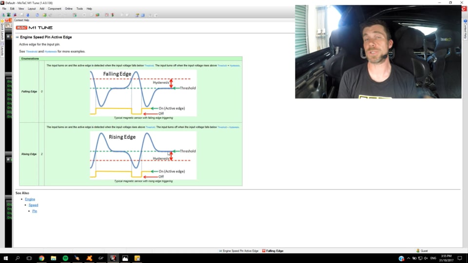
| 31:47 | But if we hook them up and we end up with a signal on our scope that looks like this, so we start, our signal begins to rise initially and then drops down through zero before rising back towards zero. |
| 31:59 | This would be set up for a falling edge trigger. |
| 32:04 | On the other hand if we had reverted the polarity, we'd get the opposite, basically a mirror image, and our signal initially drops down below zero before rising back up through zero, and then dropping down to zero and this would be a rising edge trigger. |
| 32:20 | Now the important part of this, and this is a really common area we're going to focus on in a little bit more detail really shortly. |
| 32:27 | If we have the polarity wrong or we've selected the incorrect trigger edge for whatever our polarity is, what we're going to end up with is a situation where our ignition timing will drift with engine speed. |
| 32:43 | So in other words even if we're requesting a fixed ignition timing on our laptop, we've set the entire ignition table to an across the board 20 degrees, what we're gonna find is that as our engine RPM increases and decreases, if we're watching with a timing light, the actual timing being delivered to the crankshaft to the engine is going to move around. |
| 33:05 | We'll talk a little bit more about why that's the case shortly. |
| 33:08 | OK I want to talk about that arming threshold. |
| 33:12 | So this is another really important point here. |
| 33:15 | So this is to do with the fact that the amplitude of our wave form changes with RPM. |
| 33:22 | So again on our Motec help file here, I'll just explain what we've got here. |
| 33:28 | The terminology again is going to depend on the ECU we're dealing with. |
| 33:34 | I've used the term there arming threshold but in Motec lingo this is hysteresis. |
| 33:39 | So let's just have a look here. |
| 33:40 | So we've got essentially a zero threshold here or zero point on our graph, and we've got this point listed here which is our hysteresis. |
| 33:51 | So in Link lingo this would be our arming threshold. |
| 33:54 | So the way the ECU works is that it ignores this signal entirely until it sees the input exceed the hysteresis level. |
| 34:06 | So as the tooth starts to come near the sensor we see the voltage initially rise. |
| 34:10 | As it goes up past the hysteresis or arming threshold, this means that the ECU knows that it's about to see a signal, an input. |
| 34:21 | So it basically gives it the opportunity to go, OK I'm ready, I'm looking for a signal. |
| 34:26 | So then after the signal goes past the hysteresis or arming threshold it'll continue to rise and it'll reach the peak of its amplitude, sorry for my shoddy drawing here. |
| 34:37 | And then the important point is that when that signal reaches zero or the threshold point, this is where the ECU will actually register that a trigger input, a valid trigger input has occured. |
| 34:52 | The signal will then continue back down, drop down and then it'll come back up to zero, ready to repeat the whole process again. |
| 35:00 | So the important point there is it's this point here that the ECU actually receives the valid trigger input, and it's starting by looking at the point where the voltage first exceeds the hysteresis or the arming threshold. |
| 35:15 | So long winded explanation, let's just see if we can do a little bit of freehand drawing here to give you a better idea of what's happening. |
| 35:24 | So if we look at what that signal's going to look like, again please excuse my horrible drawing, but I'll try and get this across to you. |
| 35:31 | We're going to end up at low RPM with a signal that looks something like this. |
| 35:38 | And that signal's simply going to repeat as each tooth goes past it. |
| 35:42 | So at low RPM we might have our arming threshold set somewhere around about here. |
| 35:50 | Generally we want this to be somewhere around about a third of the amplitude, just as a good starting point or rule of thumb. |
| 35:56 | We're also going to end up with a little bit of background noise that's generally occurring around about that zero volt plane as well. |
| 36:04 | So the good thing about this is that you can see the arming threshold is well above that background noise level so it allows the ECU to really clearly detect the actual signal. |
| 36:13 | Now if we look at what happens if we now increase our RPM, let's say our first example there was recorded at 800 RPM at idle. |
| 36:21 | Now if we look at what's going on at maybe 5000 RPM, we're going to see that the amplitude this time is much greater than our first example. |
| 36:32 | Again shoddy drawing but hopefully you're getting the idea. |
| 36:36 | And that's what our wave form might look like. |
| 36:38 | So the peak to peak amplitude, I should say we've got voltage here on our vertical axis, peak to peak amplitude is much much greater at 5000 RPM than what we see at idle. |
| 36:48 | And likewise we also are going to see that we're likely to find our background noise, maybe not to scale, but our background noise level will also increase. |
| 36:58 | So what we want to do is make sure that our arming threshold is also in line and we want to increase our arming threshold. |
| 37:05 | So our arming threshold at 5000 RPM's going to be quite a lot higher than when we saw it cranking and at idle. |
| 37:11 | So this is one of the most important aspects with a reluctor pickup, is to make sure that our arming threshold table is correctly set. |
| 37:20 | It's a two dimensional table, we'll have cell sites at various RPM levels and we need to set each of them. |
| 37:27 | A really common scenario that I've come across quite a number of times, I don't know if I'd say it's specific to Toyota but I definitely have noticed it on Toyota, is that the signal level from the reluctor pick ups tends to be quite low at cranking speed. |
| 37:43 | So what you can end up with is a scenario where if using a default arming threshold table, a hysteresis table, you go to crank the engine for the first time and you simply find that the ECU's reporting no RPM at all, you're sending no trigger inputs and this can be simply because that hysteresis value, the arming threshold value is too high. |
| 38:04 | So again if we just jump back to my laptop I'll just quickly draw what that would look like. |
| 38:09 | So we're getting a signal that is relatively low level, something like this. |
| 38:17 | And our arming threshold could be somewhere up like this. |
| 38:20 | So because the voltage, signal voltage, never goes above that arming threshold, the ECU is never armed, never looking for that input. |
| 38:33 | So we've talked about really broadly there, the two trigger inputs, the optical and hall style. |
| 38:40 | We've talked about the variable reluctance input. |
| 38:43 | Now we'll probably get onto one of the more important aspects which is some of the issues that you may see either on the dyno or out on the road when you are tuning an engine that is reporting some triggering problems with your ECU. |
| 38:58 | There are undoubtedly almost an unlimited number of potential areas for problems so I'm just going to focus on, again over 16 years probably what I have seen as the most typical issues that you're likely to come across. |
| 39:11 | If these are the most common ones that I'm seeing, these will probably be the first place that you wanna start in diagnosing your own problems. |
| 39:17 | So the first one, and this really goes for just about anything to do with ECU configuration would be that the setup inside your ECU is simply incorrect. |
| 39:27 | This is always the first place that you want to start. |
| 39:30 | This could include the fact that you've simply selected the wrong trigger system for your particular engine or the types of inputs that you are using. |
| 39:40 | Maybe you've selected a reluctor input but the engine is actually equipped with hall sensors. |
| 39:47 | Maybe you've selected a multi tooth trigger input but your engine actually has a multi tooth missing trigger input, that's a real common one, because you will actually see trigger data, the ECU will see information from that multi tooth missing disk. |
| 40:03 | And you may even be able to get the engine running, all be it very poorly because the trigger disk is providing that gap or those missing teeth, the ECU is expecting a constant steady angle between all of the teeth and that's going to play havoc with the way the engine runs. |
| 40:20 | Another one which we've talked about already but I'll just reiterate is using a hall sensor or optical sensor with no pull up resistor used for it. |
| 40:29 | So the ECU simply can't see the input. |
| 40:32 | Essentially here what we're talking about is if we feed garbage into the ECU, we're going to get garbage out. |
| 40:37 | This isn't the ECU's fault. |
| 40:39 | If we don't tell it what we've connected to it, what to look for, it simply can't do its job properly. |
| 40:46 | So this sort of scenario you're likely to see in an engine where you simply can't get it running at all, or the scenario I just talked about with our multi tooth missing using a multi tooth trigger input. |
| 40:56 | You may get it running but it's gonna be banging and misfiring, it's gonna be erratic, you'll struggle to keep it idling. |
| 41:03 | So those are some pretty good clues that something fundamental and serious is wrong there. |
| 41:09 | Beyond that then we also have the potential for either filtering or our arming threshold values to be incorrect. |
| 41:18 | So this is another really common one. |
| 41:20 | Generally our ECU manufacturers will provide, if we're talking about an OE configuration, they will provide data that should be adequate for your particular trigger system. |
| 41:31 | This becomes a situation where the tuners can get a little bit lazy as well. |
| 41:35 | Generally this works so often tuners don't look any further than this if we do end up with a problem. |
| 41:41 | So this will manifest itself by the fact that we may initially get no input signals from our trigger inputs, no engine speed or RPM, and the engine won't start. |
| 41:52 | We also can end up seeing trigger errors or misfires at high RPM. |
| 41:59 | So this is a really common one if we've got our arming threshold set incorrectly at high RPM. |
| 42:05 | So maybe we've got our arming threshold set OK, the engine will crank and idle OK, maybe it'll cruise at 2000, 3000 RPM OK. |
| 42:12 | But because that amplitude of our signal, our reluctor signal increases at higher RPM, if we don't take this into account with our arming threshold table we can get a scenario where the background noise can actually falsely trigger the ECU at high RPM and this will result in misfires or triggering errors. |
| 42:34 | So this can be a little bit difficult to diagnose for a lot of novice tuners because it can have very similar symptoms to an ignition related misfire. |
| 42:44 | A key point here though is if this is the sort of scenario you're running into, an ignition misfire will almost certainly be dependent on engine load. |
| 42:54 | What I mean by this is we may find that it won't happen at light throttle or low boost. |
| 42:59 | It'll get worse as we increase the load on the engine, increase the boost pressure. |
| 43:03 | If it is triggering related, generally there's no relationship there to engine load and this will be simply related to our engine speed. |
| 43:13 | Then we've got the other issue that we've briefly discussed here where we're triggering on the wrong edge of a reluctor pick up. |
| 43:20 | So this as I said is going to result in timing drift. |
| 43:24 | So essentially what happens is that the ECU is arming on the wrong part of the waveform 'cause it's looking at the wrong edge. |
| 43:34 | Now we can actually get the ignition timing dialled in correctly or calibrated correctly at a fixed RPM and if you don't know to look for this, this is something that's really easy to then ignore and you'll wonder why you've got all sorts of strange operating problems, or tuning problems as the engine speed increases. |
| 43:53 | And this is because as the engine speed increases and the amplitude of that wave form changes, what we'll find is that our ignition timing starts to drift and it can drift quite dramatically. |
| 44:05 | This is why I always recommend, it's part of our HPA 10 step process for tuning, is when we are calibrating our base ignition timing, which is always one of the first things we want to do, both before we actually get the engine started for the first time but then also once we've got the engine operating at a stable idle. |
| 44:23 | Once we've calibrated our base ignition timing at this point I always recommend bringing the RPM up to maybe 3000, 4000 RPM, well away from idle, and just confirming that at that higher RPM, our base ignition timing is still pinpoint accurate. |
| 44:40 | May see it move around a degree or so but if we're seeing this sort of problem with timing drift, we're gonna see a really dramatic change in our base ignition timing. |
| 44:49 | I'm talking in the order of maybe 15 or 20 degrees, it's gonna be really significant. |
| 44:55 | Beyond that we've also got the potential where we may have a problem with our sync position. |
| 45:02 | So this is what we were talking about earlier where ideally we want that synchronisation input to occur absolutely 50%, halfway between two of our reference or engine speed teeth. |
| 45:15 | So as we talked about we can set this at idle and low RPM and find everything's absolutely perfect. |
| 45:22 | But with belt stretch and harmonics in the valve train et cetera we may find that what works nicely at 1000 RPM may actually cause us some issues at 7000, 8000 RPM. |
| 45:34 | So if we've got a situation like this, we're again going to get symptoms that may be very similar to an ignition related misfire. |
| 45:44 | What we're going to want to be looking at is our ECU logging, we're going to want to be looking for any logged triggering errors. |
| 45:53 | Those will be indicative of the problem that we're seeing where the ECU basically is seeing too many reference inputs or not enough reference inputs between adjacent synchronisation inputs. |
| 46:05 | And when this happens essentially the ECU loses track of where it is in the engine cycle. |
| 46:10 | Depending on the ECU manufacturer, depends on how that's dealt with, but generally it's going to result in the ECU momentarily shutting down until it reacheives synchronisation and can keep running. |
| 46:21 | In the meantime it can also result in quite dramatic errors in our ignition timing. |
| 46:26 | So our ignition timing can momentarily be a long way away from where it should be. |
| 46:32 | So potentially quite dangerous. |
| 46:34 | So if we've got that sort of scenario we want to either use our built in trigger scope in our ECU or alternatively an external oscilloscope, and physically look at what the inputs are doing during a ramp run on the dyno. |
| 46:49 | And look at what happens at high RPM up around that point where the trigger error is occurring. |
| 46:56 | Quite often a lot of the aftermarket ECUs will have a parameter or channel which tells us what the relative position of the synchronisation input is compared to the reference input. |
| 47:11 | So again very dependent on the ECU manufacturer. |
| 47:14 | The Motec ECU for example uses relative sync position, I think it's called, and again if this is 50% that's ideal, we're happening halfway between two adjacent reference teeth so we can log that into the ECU and we'll often see that that will actually start dropping away and once it gets down to maybe 20% or 15%, it's getting so close to one of the adjacent reference teeth that we can end up having it swapping sides and causing that sort of problem. |
| 47:44 | The last factor and certainly not the only one, as I've said I'm just dealing with the common ones that I've experienced. |
| 47:50 | The last factor is where we've got a factory trigger system that may not be suitable for our application. |
| 47:57 | Again there's a variety of options here. |
| 48:01 | One that I'll just deal with briefly is the Nissan 360 degree optical cam angle sensor, just because it is a source of quite constant grief. |
| 48:11 | So I've got one here that I just wanted to show you. |
| 48:14 | This is the Nissan 360 degree optical sensor which sits on the front of the exhaust cam on the RB series of engines. |
| 48:24 | So we've got two signals being provided to the ECU from this disk. |
| 48:31 | Around the outside there are 360 tiny little slots, this uses an optical sensor as it's name implies. |
| 48:36 | So this gives the engine speed information. |
| 48:39 | Remember it's operating at half engine speed so this actually becomes 180 degrees input to the ECU. |
| 48:49 | Then on the inside of this there are six slots which gives the ECU engine synchronisation information and tells it what cylinder the engine is firing on at any particular point. |
| 49:05 | So there's some pluses there with that system. |
| 49:07 | First of all a lot of resolution, so we've got very fine control over the inputs to the ECU, the ECU is seeing a lot of data, this allows it to process really quickly what's happening with engine RPM and which cylinder's firing and gives the ECU the ability to very finely control the ignition timing. |
| 49:26 | The six individual slots also are different lengths. |
| 49:30 | So the ECU can decide which cylinder is firing at any particular point. |
| 49:35 | So this allows the Nissan 360 degree optical sensor on a factory ECU to actually get up and running quite quickly as a minor potential benefit. |
| 49:45 | The problem we see with that sensor is all of the issues we've already talked about. |
| 49:49 | Because we end up with problems with the belt moving around, we've got harmonics in the valve train. |
| 49:54 | This can play havoc with some aftermarket ECUs. |
| 49:59 | Now there's a fair bit of debate and discussion as to what actually causes these issues. |
| 50:03 | In my own head I've had this for a while that the potential issue is that the harmonics in the valve train essentially make this disk bounce around a little bit. |
| 50:15 | And if the disk bounces around, because the reference teeth are so close together, understandably it doesn't take much movement before the ECU may actually log one tooth multiple times. |
| 50:26 | Now as I've said that's just been an explanation I've had in my head for a fair while. |
| 50:31 | I've never really dug any deeper into finding out or proving what that theory is, I've got solutions that I know work, so I've never really felt the need to dig any deeper. |
| 50:42 | But a discussion that came up recently suggested that may actually not be what's going on and in fact it may be in relation to the way the ECU, the aftermarket ECU is processing those signals. |
| 50:54 | As I say I'm not 100% certain on what the cause of the issue is but it is definitely a real problem that we do see on some aftermarket ECUs with that Nissan cam angle sensor. |
| 51:08 | Common option there is to swap to a different trigger disk inside that cam angle sensor. |
| 51:13 | And that can, again this is up for debate, but I've proven it myself multiple time so I'm quite comfortable with it, that can actually fix the trigger issues. |
| 51:23 | In my opinion there were a few areas where that 360 degree optical disk causes issues. |
| 51:31 | The biggest one in my opinion is where we actually see trigger errors from the ECU not being able to process the data. |
| 51:39 | The 24 and one tooth trigger disks that are a common option there, in my experience have been pretty effective in resolving that although there's still the background problems that we'll see with any cam sensor where we're gonna see some minor timing jitter. |
| 51:57 | With the Nissan 360 degree optical there's also some issues potentially around backlash of the drive mechanism. |
| 52:03 | I don't wanna get too deep into that. |
| 52:04 | So long story short there, we may find that in some situations we've got a trigger disk that worked fine or trigger system I should say that worked fine on a factory engine. |
| 52:14 | Once we start modifying that engine, it may no longer work well. |
| 52:18 | With the RB in particular we find that the trigger system tends to become problematic once we start making modifications to the valve train. |
| 52:28 | So for example more aggressive camshafts with heavy duty valve springs, this changes the nature of the harmonics in the valve train and that's also fed straight into the cam angle sensor. |
| 52:40 | OK so we'll look at some techniques that we can use for diagnosing trigger errors. |
| 52:46 | So what we're going to do is have a look at how that all works. |
| 52:50 | And again I'm just gonna be using our Link G4 Plus here for a demonstration because it's nice and easy, we've got it hooked up to our 350z. |
| 52:59 | So the exact data that you'll be looking at on different brands will vary. |
| 53:06 | So let's go across to my laptop screen. |
| 53:09 | The engine is currently not running. |
| 53:11 | And I've brought up the run time value strings so this is one of my go to places in the Link G4 Plus. |
| 53:16 | What we're going to do is go across to our triggers and limits tab. |
| 53:22 | This has got a lot of information here. |
| 53:24 | For this particular demonstration there's a couple of pieces of information I'm going to be looking at. |
| 53:28 | So this is what I'm looking at when I first go to crank a freshly installed ECU on an engine, obviously we're cranking the engine not the ECU, don't quite know how that'd work. |
| 53:39 | But where we don't know we're basically trying to confirm that our trigger inputs are working correctly. |
| 53:45 | So we've got some trigger data over here on the left hand side. |
| 53:48 | In particular we've got our engine RPM or engine speed and we've got our engine speed rate of change. |
| 53:52 | We'll talk about that shortly. |
| 53:54 | So what we should be expecting if we've got the engine set up and we know that it's not going to run, so we'd probably do this by disabling the fuel injection to start with. |
| 54:05 | Maybe we would have no fuel system connected. |
| 54:08 | So at cranking speed we're probably gonna expect the engine to be seeing constant RPM, maybe in the region of about 200 to 300 RPM. |
| 54:17 | The important point is that the RPM should be relatively stable, it shouldn't be jumping up and down massively. |
| 54:24 | The other thing we're going to be looking at here is our trigger status. |
| 54:27 | So this just tells us if the ECU is seeing valid trigger inputs. |
| 54:31 | So we've got trig one signal and we've got trig two signal. |
| 54:34 | And at the moment they're both saying no. |
| 54:36 | Essentially once the ECU receives valid inputs, both of those should say yes and turn green. |
| 54:42 | Likewise we've got our trigger one error counter, and this is going to tell us if the ECU is seeing the trigger input pattern that it's expecting. |
| 54:53 | Now ideally this should say zero the whole time but quite often when we first start cranking the engine, we're going to momentarily see maybe one or maybe two trigger errors firstly get logged just as the engine begins to crank. |
| 55:07 | So just so I can do this properly, let's go through the system here and we'll actually disable our injection so the engine won't start. |
| 55:15 | We'll just store that. |
| 55:18 | Oh no we won't. |
| 55:22 | OK and we'll bring up our run time values again. |
| 55:26 | And we'll go through that. |
| 55:29 | So at the moment the engine won't start. |
| 55:31 | So what I want you to focus on is initiallhy we're gonna see trigger one turn green then moments later we should see trigger two turn green. |
| 55:40 | And then beyond that I also want you to watch the engine speed and you should see that that stays relatively constant, so let's do that now. |
| 55:51 | OK so our engine speed's saying constant 218 RPM. |
| 55:56 | I've actually just fired up briefly with probably a little bit of fuel that had been introduced. |
| 56:02 | So we'll now go back to our sequential fuel system. |
| 56:07 | So now the engine will actually start and run. |
| 56:10 | I'll bring up our triggers again. |
| 56:12 | So what we saw there is our trigger signals both went green and we had a constant engine RPM. |
| 56:18 | So now I'll start the engine. |
| 56:21 | We also see that we've got no trigger errors. |
| 56:25 | So this is all pretty healthy stuff and this is what we are hoping to achieve. |
| 56:31 | Now if you aren't getting a valid trigger input, this is where we can move to the next step which is using our trigger scope, or if we don't have a built in trigger scope, you can use an oscilloscope. |
| 56:42 | A really cheap option these days is to purchase yourself a PicoScope. |
| 56:48 | These can be purchased I think for just a couple of hundred US dollars, and they are really invaluable for diagnosing a wide range of problems with our ECUs. |
| 56:57 | And these are a PC based scope so that's why the cost has come down compared to a full bench oscilloscope. |
| 57:05 | OK so let's have a look at that trigger scope system. |
| 57:07 | So if we go to ECU controls and we go tor trigger scope, I've already got a capture there but I'll click on capture. |
| 57:13 | This can be done at cranking. |
| 57:15 | And it'll show the inputs from the trigger input so we can see there our pattern on both our cam as well as our crank. |
| 57:24 | So this will confirm that we have got trigger inputs and it's also useful for moving around and adjusting the synchronisation position so that the ECU can decode that correctly. |
| 57:37 | This is also where we would be deciding on our trigger edge particularly if we've got a reluctor or magnetic input and we were concerned about the polarity of our sensor. |
| 57:50 | Remember if you are using a reluctor sensor, you can use the trigger scope or your oscilloscope to look at the amplitude of the wave form at various RPM to help you fill in the arming threshold table. |
| 58:02 | Alright we're going to be moving into some questions and answers really shortly so if you do have any questions that you haven't asked already in the chat or the comments, please do that and the guys will transfer those through to me in a minute. |
| 58:16 | OK so now we'll have a look at some signs that you have a trigger issue. |
| 58:21 | Obviously this is beyond that fact that you can't physically get the engine up an running to start with. |
| 58:26 | So this is where I've sort of already mentioned briefly. |
| 58:31 | Often this can be a little bit confusing because a lot of trigger errors can be incorrectly diagnosed as ignition misfires. |
| 58:39 | So sometimes it can require a little bit of understanding the system to be able to correctly decide on what your particular error is. |
| 58:48 | So the first sign might be that you do have a misfire. |
| 58:52 | So again obviously could be an ignition related problem but what we'd be looking at here, if it is trigger related, is that it would be irrespective of load. |
| 59:02 | One of the key points is that we can log our trigger errors. |
| 59:06 | So we're looking to any diagnostic data that will look for triggering errors and we're looking at what happens during a ramp run on the dyno to see if triggering errors are being logged. |
| 59:17 | Now another example here would be the shape of our dyno plot. |
| 59:23 | So if we are running an engine with good triggering on our dyno, let's just jump across to our laptop screen again for a moment. |
| 59:31 | So this is a run that I did on our 350z just before this webinar started. |
| 59:36 | So at the top here we've got our engine RPM, and you can see that at the start of the run we're sitting at about 1630 RPM. |
| 59:43 | At the top of the run we got up to 5800 RPM. |
| 59:48 | The important point though is what I can do is take a line and run that straight through and we can see that our RPM traces absolutely perfectly smooth, we're getting a nice consistent rise in our engine speed with time. |
| 01:00:03 | Now bearing in mind if you're on a rolling road or you've got a hub dyno where there may be some control problems with really large increases in engine torque over a brief RPM range, we may see some erratic areas in our RPM shape but generally this will just be around the area where maybe a large turbo charger comes up on boost and the dyno momentarily struggles to properly control the load. |
| 01:00:31 | So we might see something of a hump here in the middle where the dyno just has a few moments where it's struggling to control everything and then it settles down again, so that wouldn't indicate a triggering error and that's quite common to see on high boost, high powered engines. |
| 01:00:48 | Likewise the other aspect that we're looking at here is our engine RPM rate of change. |
| 01:00:52 | So this is logging the rate of change of engine RPM just as it's name implies. |
| 01:00:57 | And again we're expecting to see a relatively consistent value here. |
| 01:01:02 | So during the beginning of our ramp run here where the engine is settling we can see that our rate of change of RPM's essentially sitting very close to zero. |
| 01:01:12 | And again during our ramp run you can see that we're consistently sitting at around about 460 RPM per second which just actually happens to coincide with the ramp rate that I'd chosen. |
| 01:01:24 | So all of that's good stuff and that's exactly what we'd be expecting to see. |
| 01:01:30 | If we have problems we're more likely to see something like, no we're not gonna see that at all. |
| 01:01:38 | Let's see if I can find where I put that. |
| 01:01:43 | That's gonna be awkward, no it's not. |
| 01:01:47 | Right we're gonna end up seeing something a lot more like this. |
| 01:01:51 | Which actually from coincidence also happens to be using a Nissan 360 degree optical trigger on a Nissan RB26 engine. |
| 01:01:59 | So what we can see here is the RPM, particularly as we get higher in the rev range, you can see it's no longer a nice straight line, it's getting quite erratic and moving around quite a bit. |
| 01:02:10 | This is also being demonstrated by our RPM rate of change. |
| 01:02:14 | So these are usually the sort of things that would indicate that we have some problems going on with our trigger input. |
| 01:02:20 | Now in this case, if we're using the Nissan 360 degree optical input, sorry if we're using anything that is cam related there, we can expect to see some of this just as a sort of a result of that location that we're getting that trigger information from. |
| 01:02:40 | So once we know all of this, we can start to decide what we're going to do about it. |
| 01:02:45 | Sometimes we can correct this in software in our setup, other times it's gonna actually physically require a trigger system change in order to get us up and running. |
| 01:02:55 | On top of these problems that we've looked at here in the laptop screen, the other giveaway would be if we were to physically hook a timing light up to the engine, and we look at what the timing has done, if we fix the ignition timing at a fixed value in our laptop screen, and we either perform a dyno run or we bring the RPM up, we're seeing the ignition timing jump around quite erratically. |
| 01:03:19 | This is again indications that we've got some triggering problems. |
| 01:03:23 | OK we will move into some questions and answers now so if you do have anything more to add to that question and answer session, please do so, and we'll see if I can help you out. |
| 01:03:41 | Andy's asked, have you run into issues where when one sensor's a variable reluctance and the other sensor is a hall and there's a phase shift issue as the RPM changes? I've never seen any problem specific to the reluctor and hall combination, that I wouldn't expect to see with either all hall or all reluctor sensors. |
| 01:04:03 | If we're getting those sensors moving around and they're getting close enough to the adjacent edge of the signal, we're likely to see issues. |
| 01:04:13 | Andy's also asked, how much timing jitter at the crank do you consider as acceptable for full power? Ah look that's a tough question, I mean ultimately I'd like to see zero. |
| 01:04:21 | That's obviously the dream if we can have exactly the correct amount of timing that we've got in our laptop screen, that's what we'd like to see, but a lot if it's really gonna depend on the engine that we're tuning. |
| 01:04:34 | So there's few considerations there. |
| 01:04:35 | What I mean by this is if we're tuning a high boost engine that's quite heavily strung and really on the edge and we're tuning that on a pump gas where we are heavily knock limited, then at this point any amount of timing jitter or movement in our timing can be problematic. |
| 01:04:52 | What this means is if we've tuned our ignition timing right to the threshold of knock, and we get a situation where timing jitter results in the ignition timing advancing perhaps a couple of degrees, this could put us over that threshold and end up with us running into knock. |
| 01:05:08 | So that's one problem, we've got a safety issue. |
| 01:05:10 | The other problem that's sort of a knock on from that is in order to prevent that situation from occuring, we need to provide a wider safety margin, basically purposefully detune or retard the ignition timing to make sure that regardless of the timing jitter, we're never running into knock. |
| 01:05:30 | So what this means is that when our timing is actually where we want it to be, we're ending up with less engine torque than we could produce. |
| 01:05:39 | So the flipside of that is if we are running an engine on a really good quality fuel such as race gas or E85, often we're going to find that we aren't knock limited. |
| 01:05:49 | So while still the timing jitter is not an ideal scenario, in these situations the knock threshold is often not a real big issue and really it's not such a big problem that that jitter occurs. |
| 01:06:03 | And I mean I know a lot of guys, I was talking to Adam from JEM, Just Engine Management, over in Australia a few weeks back at World Time Attack, and he is still running the Nissan cam angle sensor on his 960 kilowatt at the wheel RB34. |
| 01:06:25 | And he understands that timing jitter is there, but given how hard he's pushing that engine in terms of boost and the quality of the fuel that he's running on, he can't justify the expense of going to a crank trigger system when it's not strictly essential. |
| 01:06:39 | Sure if he went to that, probably would give him some advantages, but again it's all a cost versus benefit. |
| 01:06:50 | Dave has asked can you briefly touch on some of the real benefits of sequential versus batch fire on high horsepower applications? OK probably in terms of high horsepower applications, it may actually be less important than what a lot of people may think. |
| 01:07:07 | Really the benefits of sequential fuel injection, there we're talking about fuel injection rather than ignition timing, the benefits of being able to control each of the injectors and time the injection pulse specifically to the valve opening event is more beneficial and more important at idle and low RPM, than it is at high RPM. |
| 01:07:30 | So really it's more of an issue in my opinion for road cars that are gonna spend a lot of time idling and a lot of time cruising. |
| 01:07:39 | Particularly becomes a bigger issue with these engines also when you've fitted them with really large injectors. |
| 01:07:45 | So at the other end of the spectrum, when we're talking about the operation under very high horsepower levels, it actually becomes much less important and the reason for this is if you consider the operation of an injector, most of us would be quite happy in seeing our injector duty cycle sitting somewhere in the order of maybe 70% to 85% at peak. |
| 01:08:07 | And under that situation, what you need to realise is that the injector is essentially open for the majority of the engine cycle. |
| 01:08:15 | When you've only got a window where it maybe closed for maybe you know 15% to 25% of the engine cycle, understandably shifting the actual phasing of the injector around isn't going to have a real big benefit. |
| 01:08:29 | So yeah it's more really important in a road car application where you really want good idle quality, good cruise economy, those sorts of things, minimal emissions if you're worried about those as well. |
| 01:08:47 | I'll also just touch there, I'm pretty sure your question Dave, was related to the injection side of things, I will just touch on the ignition side because I mentioned that during the webinar there. |
| 01:08:57 | So in my own experience, realistically, provided you're using good quality coils, waste spark is actually an incredibly effective ignition system. |
| 01:09:09 | And I've used that even on some really high power drag engines. |
| 01:09:13 | You can argue though that at high RPM, the available dwell time for a waste spark system is reduced when compared to direct spark so there can be some benefits in a direct spark system at very high RPM and in high boost applications where we do need as much spark energy as we can get. |
| 01:09:36 | Obviously a waste spark system is firing the ignition coil twice as often as a direct sparking system. |
| 01:09:45 | Lee has asked what's the best way to check timing on a crank trigger with no degree wheel? That is a tricky one and it does come up occasionally. |
| 01:09:52 | Unfortunately a lot of engine manufacturers weren't kind enough to provide us with timing reference marks on the crank pulley and the front cover of the engine. |
| 01:10:00 | If that's the situation, what we actually need to do, is create our own timing marks. |
| 01:10:05 | This is a bit of a pain in terms of the job, but it does need to be done otherwise we've got no accurate timing marks. |
| 01:10:12 | So the way I do this is to use a modified spark plug. |
| 01:10:15 | I've got a spark plug where I've welded a piece of steel bar to the end of the spark plug, which protrudes down into the cylinder. |
| 01:10:23 | So this is around about 25 millimeters longer than the spark plug would normally be. |
| 01:10:28 | So what we'll do is remove all of the spark plugs, wind this gently into number one cylinder. |
| 01:10:32 | It's really really critical if you're using this positive stop method that we make sure that there is no chance that the engine could be cranked over, otherwise you're going to end up punching a nice neat little hole through the top of your piston and it's not gonna be a happy day. |
| 01:10:46 | What we're going to do now is wind the engine over by hand using a ratchet on the crank pulley, and we're going to gently wind it over until the piston comes up and contacts that stop. |
| 01:10:57 | We're going to make a reference marks against the engine block and we're going to make a mark on the crank pulley in line with that reference mark. |
| 01:11:05 | Once we've done that we're going to then rotate the engine in the opposite direction and turn it over again until the piston comes up and contacts that positive stop, and we're gonna make another mark on our crank pulley. |
| 01:11:16 | If we've done that, what we're going to find is that true top dead centre is going to be exactly halfway between those two marks that we've put on our pulley. |
| 01:11:23 | So we wanna make a permanent mark there, permanent mark on our engine front cover, or wherever we can see that, and that's going to be our TDC mark which we can use for setting our base ignition timing. |
| 01:11:39 | Daniel Davis said would it be better to have a six tooth trigger over a three tooth trigger on a three cylinder? Would the ECU be better able to predict engine speed? Yeah this really goes back to what I was discussing earlier where the more teeth the engine speed input has, the more information the ECU receives, so the better it's going to be able to cope with changes in engine RPM between adjacent teeth. |
| 01:12:06 | So we're going to see more consistent ignition timing. |
| 01:12:10 | As I also mentioned, this becomes a bigger problem at low engine speeds so less of an issue at high RPM, but certainly if we want the engine to idle at maybe 700 or 800 RPM and we want really nice stable ignition timing, a three trigger disk is probably not going to be ideal there. |
| 01:12:29 | Kasvin has asked, on some engines, let's say a Honda, there are piston position sensors alongside with crank and cam position sensors. |
| 01:12:37 | Is this also considered by the ECU when trying to sync? I'm not entirely sure exactly what sensors you're talking about there. |
| 01:12:47 | So what we can see on engines that have variable valve timing is that we will have a crank position sensor so engine speed sensor, we may also have a single tooth synchronisation sensor on the cam or one of the cams, and then on top of that we may also have cam position sensors which are used for variable valve timing, this all really depends on what that particular engine manufacturer decided was the ultimate. |
| 01:13:19 | Andy's just made a comment, one of his engines revs at 12000 RPM per second on a throttle stab, crank teeth is a huge issue at these acceleration rates. |
| 01:13:29 | Yeah quite potentially that would be a problem, yeah, yeah, definitely. |
| 01:13:35 | Alright guys that's brought us to the end of our questions so hopefully you've learned a little bit more about trigger systems that may shine a little bit of light on some of the terms that you weren't quite fully understanding and giving you a better idea of maybe what to look for when trying to diagnose some of these problems when you're on the dyno and just facing triggering problems. |
| 01:13:55 | As usual if you've got any further questions that crop up after this webinar has aired, please ask those in our forum and I'll answer them there. |
| 01:14:04 | Thanks everyone for joining us. |


