151 | Your Guide to Engine Building Tools
Summary
Regardless whether you’re a home enthusiast or a professional engine builder, you’re going to need a range of specialist tools to perform your job and get the best results possible. In this webinar we’ll cover what we consider to be essential tools that every engine builder should have in their tool box.
| 00:00 | - Andre from High Performance Academy here, welcome to another webinar. |
| 00:04 | In today's webinar we're going to be having a look at some of the tools that you're going to require in your tool box if you want to start assembling your own engines. |
| 00:14 | Now this is something of a controversial topic because a lot of people mistakenly think that if you want to start assembling or building your own engines, that you're going to have to shell out hundreds of thousands of dollars, if not at least 10s of thousands of dollars, for some specialist tools and specialist equipment in order to achieve that aim. |
| 00:35 | So today's webinar is designed to show you that that's not necessarily the case. |
| 00:40 | Of course everyone has a budget and the amount of money that we want to spend on tools and what we actually require is really going to depend on how involved in the engine building process we want to be. |
| 00:55 | And at one end of the spectrum we obviously have professional engine machinists and professional engine building workshops where every single task from the cleaning and machining of the engine block through to the final assembly of the block, the engine, is handled in one place. |
| 01:12 | And then there's the aspects that we're going to look at where we're going to be working in conjunction with an engine machinist in order to perform those machining tasks. |
| 01:21 | So really important to start by saying that when we're talking about engine assembly or engine building we're talking about working in conjunction with a professional engine machinist to do the hard work of actually machining your bare engine components. |
| 01:38 | Now it's not something that we can expect to do as home enthusiasts or even as semi professional workshops, it's not something we can hope to really bring in house, all of that machining work. |
| 01:50 | If we are talking about doing that then in this case, yes there can be hundreds of thousands of dollars worth of specialist machinery in order to perform all those machining jobs. |
| 01:58 | But probably just as importantly, all of those machines also require specialist training, years of training in order to get the right results out of them. |
| 02:08 | That's not what we're talking about here. |
| 02:12 | Now what we want to really show is that basically anyone with the right sort of mindset, an eye for detail, attention to detail, and patience, with a modest mechanics tool set, and a few specialist tools can actually do a really good job of assembling your own engines. |
| 02:33 | Now I've sort of mentioned what you actually are going to need in terms of tools is going to very much depend on how much of the engine assembly process you want to get involved in. |
| 02:44 | And what I mean by this is it is quite possible to send all of your components out to a machine shop and basically ask them to do every last aspect other than the final assembly. |
| 02:56 | In other words measure and check all of your clearances, machine all of the components, set aspects such as your piston to bore clearance et cetera, then when you get all of the components back, it's simply a task of cleaning and performing a final assembly. |
| 03:11 | I really strongly believe though that if you want to be involved in the engine building process at any level, it becomes the job or responsibility of the person doing that final assembly to check and make sure that all of the tolerances and all of the clearances are exactly what they should be or what you want them to be and if anything is wrong it really becomes the person doing that final assembly, it becomes their responsibility. |
| 03:40 | So that's something really important to understand. |
| 03:43 | While yes you can just get all of your components back from the machinist and assemble them, hence requiring a really limited set of specialist tools, this can open you up for some awkward conversations when something goes wrong, and inevitably there ends up to be some finger pointing between you and the engine machinist and that never really ends up working out well. |
| 04:05 | The other aspect to consider is the tools that you will require are going to depend to a degree on the engine that you are building. |
| 04:13 | So not every engine is exactly the same and some engines do require some special service tools. |
| 04:20 | So these may be required for some certain assembly or disassembly operations. |
| 04:25 | Sometimes we can get around it, we can modify an existing tool, but other times we really do need a special service tool so that's a consideration. |
| 04:35 | Obviously if you are going to be working on that same type of engine repeatedly, then it simply makes sense, a lot of these special service tools are actually quite cheap, and it's inevitable that you're also going to end up adding to your engine building toolbox over time. |
| 04:51 | So we're going to start by at least assuming that you already have what I'd consider to be a basic mechanic's tool set. |
| 05:00 | So here I'm assuming that you're at least already involved in the industry to some degree, you're already probably spinning spanners on your own cars and you've already collected what I'd consider to be the bare basic fundamentals of a mechanic's tool set. |
| 05:15 | So here I'm talking about a good set of quality sockets, I'm talking here about half inch, 3/8th drive and quarter inch, so you've got a full range that will work on various different fasteners. |
| 05:28 | Also going to need some extensions et cetera so you can get into some of the tricky places you're likely to be working. |
| 05:35 | Obviously on top of that also spanners, screwdrivers, pri bars et cetera. |
| 05:40 | These are what I consider to be the basics and they aren't specific to engine building but we will definitely be using them. |
| 05:48 | We're going to move on now and we'll talk about some of the more specific tools that we really do need for engine building. |
| 05:55 | Although again some of these will cross over to general more mundane mechanical tasks. |
| 06:00 | So we'll start with the torque wrench, and I've got in front of me here a Snap-on half inch drive digital torque wrench, which is one of my favourite tools. |
| 06:10 | You don't have to be going and purchasing an expensive digital torque wrench like that though. |
| 06:17 | You're also going to probably require a couple of different torque wrenches. |
| 06:23 | So this particular model here is a half inch drive, from memory this one will go between about 25 foot pound of torque and 250 foot pound of torque. |
| 06:32 | In some instances that bottom limit at 25 foot pound, may already be above the specified torque range for a certain fastener. |
| 06:41 | And in that instance you're going to be in trouble because there's no way of correctly torquing that fastener so you'll probably find that you'll also need perhaps a 3/8th drive torque wrench which will go across a much lower torque range. |
| 06:57 | Now the important thing to understand here as well is when you are using a torque wrench on some of the mission critical fasteners that we have in our engines, it is really important that that torque wrench is accurate. |
| 07:11 | And something that a lot of people, even professional mechanics don't understand or realise is that we can actually have our torque wrenches checked and calibrated. |
| 07:20 | There are specialist companies around that will calibrate or check your torque wrench settings. |
| 07:26 | And generally on something that I'm going to be using for engine assembly I'd like to have that checked around about once a year just to ensure that it is still correct. |
| 07:34 | So for example what I'm talking about here is if we're maybe tightening up the wheel nuts on our car, it's probably not going to be the end of the world if the wheel nuts are over torqued by perhaps five foot pound. |
| 07:48 | Chances are they'll probably be just fine if they're under torqued by five foot pound as well. |
| 07:52 | We've also got five, or maybe six, or four wheel nuts holding your wheel onto your car. |
| 07:57 | Much less likely to want to over torque or under torque a really critical fastener such as a connecting rod, big end bolt because that could result in a catastrophic engine failure so as we're starting to deal with some of these high performance engines, we really wanna be crossing the t's and dotting the i's and make sure that everything is absolutely perfect. |
| 08:17 | Now one of the reasons that I do have the digital Snap-on torque wrench is that this torque wrench also does torque angle. |
| 08:25 | So this means that we don't need to add a torque angle gauge as well as our torque wrench, we'll have a look at that anyway for those of you using a mechanical torque wrench. |
| 08:36 | The torque angle is all done through the torque wrench so particularly if you are dealing with torque to yield fasteners which are very common in a lot of OE applications, that's going to be handy, it's gonna be a time saver. |
| 08:49 | Also the torque angle gauge, the separate torque angle gauges can be a little bit tricky to use if you're not familiar with them. |
| 08:56 | So using a digital torque wrench with the torque angle feature means that you're going to probably be able to be more consistent with the angle that you are using. |
| 09:04 | Regardless whether you're using a digital torque wrench like this or a conventional torque wrench, most of the torque wrenches we'll be using are what's referred to as dual signal. |
| 09:13 | This is another just important thing to keep in mind. |
| 09:16 | We want to know when we have reached our torque preset so a dual signal will give us two indications that we're reached that torque setting. |
| 09:25 | So for example on our Snap-on gauge it has a buzzer that will actually beep at you to let you know you've reached that torque setting, but in a noisy workshop environment, often this can be easy to miss, so the other thing it will do is vibrate through the handle of the torque wrench. |
| 09:41 | So that's something to keep in mind, just a couple of different ways of letting you know that you have reached your torque preset. |
| 09:48 | Now I've already talked about the torque angle gauge so this is what a torque angle gauge looks like. |
| 09:54 | Let's just jump to our overhead camera so we can get a better look at this. |
| 09:59 | So it has a degree wheel here so we can set or measure the degrees of rotation. |
| 10:05 | One end will simply connect into our torque wrench and on the other end we'll connect our socket or extension. |
| 10:12 | You can see we've also got a little positive stop which we can use to locate against something to prevent the torque angle gauge from moving. |
| 10:20 | So these are relatively cheap and pretty easy to get. |
| 10:23 | But as I've said they are a little bit fussy to use if you're not familiar with them. |
| 10:29 | It's important to make sure that you make sure that torque angle gauge doesn't rotate, otherwise you're going to get a false reading. |
| 10:37 | OK one of the, probably more specialist tools, that we're definitely going to need for engine building is a ring file. |
| 10:46 | A lot of the rings that we'll be fitting, particularly those that come with aftermarket forged pistons are what is referred to as a file fit ring. |
| 10:55 | And these rings come with a gap out of the box that is too tight so if we simply drop those rings in and fit them to our pistons, we're going to end up with a huge problem because those rings in operation will butt together as they expand with heat and this can result again in catastrophic engine damage. |
| 11:13 | Very easy to have them seize in the bore and essentially rip the crown off the piston, so we definitely don't want that happening, so we need to set our ring gaps to suit whatever our application is. |
| 11:24 | So we've got a couple of options that we're going to look at here. |
| 11:28 | I'll jump across to our little remote camera and what I've got in front of me here is a Total Seal piston rings electric ring file. |
| 11:38 | So this is a little bit of a pricey tool, I think these are somewhere in the region of about USD$400 So it actually uses an electric motor. |
| 11:45 | We've got a grinding wheel in here, and we place the ring on this bed. |
| 11:52 | One of the nice features with these electric ring files is we can adjust the bed where the ring sits. |
| 11:58 | So in particular this allows us to adjust the ring file to suit different bore diameters. |
| 12:03 | Allows us to make sure that across a set of rings we're always getting square ring end gaps, making sure that the two ring end gaps are parallel. |
| 12:12 | Another feature with this particular tool is we have a dial gauge here which allows us to see very accurately how much material we have removed from the ring. |
| 12:22 | So essentially we'd place the ring in the file and then there's a small thumb wheel we can use here to adjust how far in or out the bed is located and then we can grind material from the ring. |
| 12:34 | So these are definitely worth considering if you are getting into engine building as an occupation and you think you're going to be building a number of engines. |
| 12:44 | So definitely something that I would not even think twice about if you're setting up a workshop for this sort of purpose. |
| 12:52 | For the home enthusiast though where you're only building perhaps one or two engines, then it can be a little bit hard to justify that sort of expense but there are alternatives as well. |
| 13:02 | There are very cheap manual ring files available. |
| 13:05 | So I've got one of those here. |
| 13:09 | And these can be purchased for as little as USD$20 to USD$50 You can get them from all of the usual sort of suppliers you might see JEGS, Summit, eBay. |
| 13:20 | And it has a grinding wheel located in the bed and obviously this is just turned by hand. |
| 13:27 | We'd place the ring on the bed there. |
| 13:30 | There are a couple of little dowels to locate the ring. |
| 13:33 | So these can be used quite effectively but they do require a little bit more care. |
| 13:39 | Because there's nothing to consistently locate the ring and we need to be doing this manually. |
| 13:44 | It is much easier to end up with our ring end gaps not square to each other or not parallel to each other, and we've also obviously got absolutely no indication of how much material we are removing. |
| 13:57 | So does require patience, does require a little bit of attention to detail and care, but certainly it is possible to do a really good job with a manual ring file. |
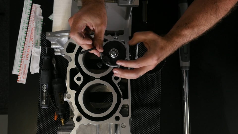
| 14:10 | OK while we're talking about rings here, another tool that we are going to need is a ring squaring tool. |
| 14:17 | So what this is used for is squaring the rings in the bore prior to measuring the ring end gaps. |
| 14:24 | So let's just go to our overhead camera here, and we've got one of our rings on a Subaru FA20 block. |
| 14:30 | And when we go about measuring our ring end gap, what we want to do is locate the ring in the top of the cylinder. |
| 14:37 | But we need to make sure that first of all the ring is located a little way down from the top of the cylinder. |
| 14:43 | This will just take out the effect of any potential veer or taper at the top of the bore. |
| 14:47 | And we also need to make sure that that ring is square in the bore. |
| 14:50 | So our ring squaring tool has a number of little pockets cut out around the outside of it, and all we need to do is compress the ring squaring tool, drop it down on top of the ring, and then gently press down on the ring, and what that will do is move down the bore, down the cylinder until those little pockets locate on the top of the bore. |
| 15:11 | So that makes sure that the ring is located a consistent distance down the bore. |
| 15:16 | Now these are incredibly cheap so there's really no reason not to have one, they make your life a lot easier, they are universal, you can adjust them for multiple bore diameters however if you are without one of these, all is not lost. |
| 15:29 | Another option that I quite frequently use is to fit either the second compression ring or the oil control ring onto one of your pistons, and then you can use the piston, place it upside down in the bore, and you can then press that down on top of the ring, and that'll have the same effect. |
| 15:47 | This does require that you're using here a flat top piston though. |
| 15:52 | So it's not going to work if you've got a heavily domed piston. |
| 15:56 | But essentially all it's going to do is move down until the second compression ring locates again on top of the bore. |
| 16:03 | So again it's a great quick and easy way of squaring the ring in the bore and locating it down the correct amount. |
| 16:11 | OK particularly for the home enthusiast, really really cheap way of measuring our bearing clearances or checking our bearing clearances is to use Plastigauge. |
| 16:21 | I've done a number of webinars about this particular product. |
| 16:25 | They're available for our gold members in the archive as well if you do wanna see exactly how to use Plastigauge. |
| 16:31 | Also included in our engine building courses as well. |
| 16:36 | So Plastigague is just simply a thin wax strip. |
| 16:40 | We can lay this across the journals on the crankshaft. |
| 16:44 | We can then assemble everything without lubricating oil, we can torque down our bearing caps, then remove them and what happens is that that wax strip is crushed out, we can then measure how wide that wax strip is and this is going to give us a good indication of what our bearing clearance is. |
| 17:01 | Now this is a product that causes a lot of controversy. |
| 17:05 | There are a lot of professional engine builders out there that have very negative views about Plastigauge. |
| 17:11 | Now I've been building engines for probably about 16 years now. |
| 17:14 | I still like to keep a pack of Plastigauge handy, and you're going to also find that a lot of professional engine builders out there in the market, still do exactly the same thing, using Plastigauge as a last minute sanity check just to ensure that everything lines up with what we've previously measured using a micrometer and a bore gauge. |
| 17:35 | Really really cheap, you can but a pack of plastigauge for just a few dollars. |
| 17:40 | OK if you wanna get a little bit more serious though with your engine building and you really want to be able to measure all of your clearances accurately, all of the components accurately, and make sure that they are where they should be, then you are going to need some more specialist equipment and of course this does come with a price tag. |
| 17:58 | So in particular here you're probably going to want to invest in a good set of micrometers. |
| 18:06 | So I've got a couple here. |
| 18:08 | When I say a set, we are going to need a number of micrometers. |
| 18:13 | Each of these micrometers will only measure a one inch range. |
| 18:17 | So in order to measure the entire range of clearances or product diameters that we are likely to encounter with engine building, we're going to need a number of different micrometers. |
| 18:28 | So that's why they come in sets, well they can be bought individually but generally if we're purchasing new you're probably going to want to look at purchasing a full set. |
| 18:38 | Now there's a few considerations that you need to make if you're in the market for micrometers. |
| 18:43 | First of all they vary dramatically in price. |
| 18:46 | So if you're looking at some of the higher end name brand models that are very well recognised, the likes of Mitutoyo, then you are going to be spending a lot of money on those micrometers. |
| 18:58 | For a good quality set from the likes of Mitutoyo you're probably going to be looking in the vicinity of USD$700 to USD$1000 or more for a full set. |
| 19:06 | The other aspect that you're going to need to consider. |
| 19:09 | Sorry I'll go back, these days there are some really decent reliable options coming out of China. |
| 19:17 | Now I know a lot of you are probably cringing right now. |
| 19:19 | There's a lot of nasty connotations with Chinese products and definitely some of them are 100% justified. |
| 19:25 | However there are now a lot of really cost effective and quality items coming out of China. |
| 19:32 | And this particular set that I've got in front of me here is a Chinese brand. |
| 19:37 | These were purchased for around about USD$300 for the full set. |
| 19:42 | Now when it comes to micrometers there are a few more decisions you're going to need to make. |
| 19:46 | First of all you're going to need to decide whether you want to be measuring in metric or imperial units. |
| 19:54 | Now it doesn't really matter which way you go. |
| 19:57 | Obviously if you live in a metric world, metric country, where the metric system is used, then it would on face value make sense to be purchasing a metric micrometer set. |
| 20:10 | Here in New Zealand we tend to use the metric system however I still do most of my engine building in imperial units. |
| 20:19 | The reason for that is a lot of the products that we will be purchasing, the likes of pistons, the likes of camshafts et cetera, are coming out of the United States, and the United States obviously still use the imperial system. |
| 20:33 | So regardless which way you decide to go with your micrometer or your measuring equipment scale, what units you're going to be using, it's also important to be able to easily convert from one to the other, which is really easy if you just remember that there are 25.4 millimetres in one inch. |
| 20:54 | Now the last part is I know that a lot of novice engine builders and mechanics for that matter, are a little bit scared about reading a micrometer. |
| 21:02 | So these particular micrometers have a vernier scale. |
| 21:06 | And instead what they'll want to do is purchase a digital micrometer. |
| 21:11 | Now there's nothing particularly wrong with that but what you are going to find is that the cost for a single digital micrometer is much much higher than a conventional vernier style micrometer. |
| 21:23 | So if you're buying a full set it's going to really add to the cost. |
| 21:26 | And it's actually a really good skill to have, to understand how to use a micrometer, how to read a micrometer properly. |
| 21:33 | If you understand that it's actually really quick and easy and there's no problem. |
| 21:37 | So again that's contained in our engine building courses as well. |
| 21:43 | Now moving on, the micrometer set is really only one part of the puzzle when it comes to measuring the likes of our bearing clearances. |
| 21:51 | The other product we are going to need to work in conjunction with a micrometer is a bore gauge. |
| 21:58 | So let me just get that out here. |
| 22:03 | So this is our Insize bore gauge. |
| 22:07 | And the bore gauge, I'm just showing you the complete kit here. |
| 22:12 | This bore gauge is useful for any diameter from 50 millimetres through to 160 millimetres, via these little adapters which we can see here. |
| 22:24 | Alright so with that out of the way I'll pull the bore gauge out and explain a little bit more about how exactly it works. |
| 22:31 | So the bore gauge or dial bore gauge as it's often referred to, is a tool that's got a dial gauge at the top of it, and what we're going to be doing is using this dial bore gauge in order to measure the inside diameter of a product. |
| 22:46 | So as it's name implies, often used to measure bore diameters. |
| 22:51 | So in this case we can use the dial bore gauge to check the bore diameter. |
| 22:56 | In particular what we can do is use it to confirm that the bore is round, there's no out of round if we measure in two plains. |
| 23:05 | And we can also make sure that the cylinder walls are parallel from top to bottom. |
| 23:10 | So by moving the bore gauge up and down the bore we can check that there is no taper or belling in our bores. |
| 23:18 | Now the dial bore gauge itself doesn't actually give us a measurement for the component that we are measuring. |
| 23:26 | So it won't actually tell us what our bore diameter is. |
| 23:29 | Instead what we need to do is first of all zero our dial bore gauge. |
| 23:33 | So what we'd do for example, if we were wanting to check our piston to wall clearance, we would take our micrometer, and we would measure the skirt diameter of our piston at the correct location as per the manufacturer's specification. |
| 23:49 | Once we've got that diameter, we can then take our bore gauge and we can run it through our micrometer which is a bit fiddly, and what we are essentially doing is zeroing our dial bore gauge at the outside diameter of our piston skirt. |
| 24:05 | Once we've correctly zeroed our dial bore gauge, then we can run the dial bore gauge down the cylinder bore and the dial indicator is going to show us the difference. |
| 24:15 | That's what it's doing, it's showing us the difference between the outside diameter of the piston skirt and the inside diameter of the bore. |
| 24:23 | Likewise if we are using our dial bore gauge to measure a bearing clearance, we're going to measure the journal diameter of our crankshaft using our micrometer, we're going to zero our dial bore gauge on our micrometer, and then we're going to insert the dial bore gauge into either the conrod big end journal or alternatively the main bearing tunnel in our crank case in our engine block, and that's going to then show us what our oil clearances are. |
| 24:52 | OK moving a little further into some of the more fiddly and specific tools that we may like to consider. |
| 25:00 | Now these definitely aren't essential, but it is also quite possible for us to balance our own engine components at home. |
| 25:07 | So this is an optional part. |
| 25:10 | So there's no need to do this, you can definitely ask your machinist to balance your engine components. |
| 25:15 | And particularly when it comes to the actual crankshaft itself, the rotating components in the engine, these need to be balanced by a machinist, we can't do this at home. |
| 25:25 | It requires expensive specialist machinery. |
| 25:28 | But certainly in terms of our pistons and our connecting rods, it is possible to balance these components ourselves. |
| 25:35 | For a start, if we're just talking about balancing pistons, all we're going to need is a reasonable set of scales. |
| 25:44 | I would personally recommend a set of scales that can measure up to about two kilograms. |
| 25:50 | And with an accuracy of a tenth of a gram. |
| 25:54 | So these are available again now quite cheaply thanks to a lot of the products coming out of China, and again some of these products are actually incredibly good. |
| 26:03 | It's important if you're using one of these cheaper brands of scales just to make sure that you can get repeatable results. |
| 26:09 | So if you basically measure the same piston or same component multiple times, place it on the scales, take it off, place it on the scales, and do this maybe five or six times, we wanna really make sure that you are getting accurate reliable repeatable results. |
| 26:24 | So that's actually more important than the actual accuracy of the measurement that we're making. |
| 26:30 | So in terms of measuring and balancing our pistons, this is all we're going to need, a set of scales, and we're going to need a way of removing material from the scales. |
| 26:39 | Now this can be done with a simple air die grinder with a carbide grinding bit on it. |
| 26:46 | We can also use something like a power file. |
| 26:50 | I've also got a Dremel tool here. |
| 26:54 | This has actually got a cutting wheel on it at the moment but we can obviously fit a variety of different grinding bits to the Dremel die grinder. |
| 27:03 | It's really important when we are removing material from our pistons to make sure we do it in a sensible location where it's not going to affect the strength of the piston. |
| 27:13 | This is normally done from the underside of the wrist pin boss. |
| 27:17 | And we also want to make sure that we leave a nice smooth finish on the underside of the piston, that it's not going to result in any stress raises. |
| 27:25 | Now moving one step further with our engine balancing, we may also want to consider balancing our own connecting rods. |
| 27:33 | And that gets a little bit trickier. |
| 27:35 | I'll just bring our connecting rod balancing fixture out here. |
| 27:39 | So when we're talking about our connecting rods, we actually need to weigh and balance the big end and the wrist pin end of our connecting rods separately. |
| 27:50 | So I'll just turn this around as well, maybe we can get a slightly different angle on this. |
| 27:58 | So this is a fixture designed for exactly that purpose. |
| 28:02 | What it does is it supports the connecting rod, as you can see you can balance the connecting rod by its small end. |
| 28:09 | There is another fixture that we place on our scales that then we can locate the big end of the connecting rod on. |
| 28:16 | So this allows us to separate the pin end and the big end of the connecting rod and weigh them separately. |
| 28:23 | And the reason we need to do this with the connecting rod is because of the way the connecting rod operates. |
| 28:27 | Part of the mass of the connecting rod is considered to be rotating and part of it is considered to be reciprocating. |
| 28:34 | So when it comes to balancing a connecting rod we don't simply weigh all of our connecting rods and make sure that they weigh the same. |
| 28:41 | We actually need to make sure that all of the big ends of our connecting rods weigh the same. |
| 28:46 | Once we do that then we can in turn remove material from the small ends until the overall weight of all the connecting rods is exactly the same. |
| 28:54 | Now these weighing fixtures here, I think the one that we're looking at right now, it's from Proform is around about USD$70 or USD$80 So it's not a huge cost but certainly if you're only doing one engine it's probably not something you'd want to consider and getting your machinist to do the work for you is going to be probably a more cost effective way of doing it. |
| 29:15 | The other thing to consider as well if you are looking at these fixtures, this particular unit has ball bearings that support the connecting rod. |
| 29:25 | Basically this is just designed to reduce the friction so that we can get consistent results when we're removing the connecting rod and replacing it, we can get consistency from one measurement to the next, so that just makes sure that we are balancing our components correctly. |
| 29:44 | One last aspect there about the engine balancing as well, is if you are building a v configuration engine, so V6, V8 et cetera, then the weight of your wrist pin and you piston, your rings, and also your connecting rod, actually needs to be taken into account in order to balance the crankshaft. |
| 30:08 | So this is called a bob weight, and these bob weights are calculated out based on your component weights, and then these bob weights are physically added to the crankshaft journals during the crankshaft balancing process. |
| 30:20 | So obviously in this case if you are dealing with one of these engines, if you choose to balance your pistons and connecting rods, these would need to be done prior to your machinist balancing your crankshaft. |
| 30:31 | OK moving on with some of again the more specific engine building products, tools that you may want to consider. |
| 30:40 | Here we've got a burette. |
| 30:43 | So probably some of you might remember these from chemistry class. |
| 30:47 | And using the burette in conjunction with a piece of clear plastic here which has a single hole drilled in it, we can use these products for what's called cc-ing a combustion chamber. |
| 31:02 | So this allows us to see what the capacity of a combustion chamber is. |
| 31:09 | This allows us, it's one of the blueprinting tasks, allows us to adjust the combustion chamber volumes across all of the cylinders to ensure that they are the same. |
| 31:17 | It's just one step involved in making sure that we have an even compression ratio across all of our cylinders. |
| 31:22 | So in this case the clear plastic is located on the top of the combustion chamber. |
| 31:27 | Normally what we'd do is actually seal this to the deck surface of the head using a little bit of light grease and then generally we'd use a coloured or slightly dyed water and we can fill the combustion chamber and take note of how much or what volume of water goes into it. |
| 31:44 | So again something that's relatively cheap and relatively easy to use. |
| 31:50 | But it's only going to be useful to you if you want to get involved in your own head modifications or head porting. |
| 31:59 | Moving on, another product that I'd consider to be slightly more specialist is our deck bridge here. |
| 32:06 | So this can be used in conjunction with the dial gauge that you can see is already fitted to it. |
| 32:12 | This can be used in order to check the piston to deck clearance. |
| 32:18 | So in other words we're checking how close to the deck surface of the engine block the piston comes. |
| 32:23 | So it's pretty simple, really just locates across the deck of the engine block and we can zero the dial gauge before we use it on a part of the deck and then we can bring the piston through its full travel, rotate the crankshaft through its full travel, and we can see whether our piston is coming up to the same height as the deck of the block in which case we'd call it a zero deck piston. |
| 32:53 | Whether it's protruding or whether it's sitting down from the deck of the block. |
| 32:57 | So this is important when we are confirming our piston to cylinder head clearance. |
| 33:06 | Another quite specialist tool, if I can find where I have put it. |
| 33:13 | Yep here it is. |
| 33:15 | Another specialist tool that we may want to consider for very high end, high performance engines, is a rod bolt stretch gauge. |
| 33:24 | So while conventionally most of us will be tightening the connecting rod bolts using a torque wrench. |
| 33:31 | Really the preferred technique is to directly measure the stretch. |
| 33:35 | So this conrod bolt stretch gauge is a special fixture that again contains a dial gauge. |
| 33:41 | And we can locate the stretch gauge on either end of our connecting rod bolts. |
| 33:47 | So what we'll find is that with performance conrods, there's actually a little divet on both ends of the rod bolts. |
| 33:54 | And what we can do is locate the stretch gauge on our rod bolt and using the dial gauge we can check how much the rod bolt has stretched. |
| 34:05 | So this is a process that we use while we're torquing or tightening that fastener down, and we go through several stages of applying a little bit more torque to the rod bolt, repositioning the stretch gauge, and seeing what the actual stretch is and we will find that all of the high end fastener manufacturers will provide a recommended stretch reading for those rod bolts. |
| 34:32 | The connecting rod bolt is quite unique in so much as it's one of the few fasteners where we can generally get to both ends of the fastener and actually use the stretch gauge. |
| 34:41 | For example if we're talking about a head stud or a head bolt it's impossible to get to both ends of that fastener so we have to make do with our torque rating instead. |
| 34:55 | Now we've already seen our dial gauge. |
| 34:57 | I had our dial gauge fitted here to our deck bridge. |
| 35:01 | But another product that we will want to have is just a reasonable quality dial gauge and magnetic base. |
| 35:11 | These are useful for a range of tasks. |
| 35:13 | You can use them for checking for example the thrust bearing clearance in an engine block by locating the magnetic base on the front of the engine block and locating our dial gauge on the snout of the crankshaft and then moving the crankshaft forward and back. |
| 35:29 | Also really critical to have one of these while we are dialling in cams. |
| 35:34 | The idea with the magnetic base is that by manipulating the angle or location of these arms, we're able to get that dial gauge located exactly where we want it. |
| 35:48 | So it's really critical particularly if we are trying to measure valve lift because we want to make sure that that dial gauge is working directly in line with the opening movement of the valve. |
| 36:01 | We don't want it off to an angle, it's not going to give us a true reading. |
| 36:04 | So again we can get all of those products now really really cheaply so there's no real reason not to have something like that. |
| 36:13 | Seeing as I've just talked about degreeing cams as well, if you are going to be doing that with a performance cam you are going to need a degree wheel. |
| 36:22 | This one is massive, I know. |
| 36:24 | It's a Moroso pro wheel. |
| 36:26 | These, we need to locate onto the nose of the crankshaft and we can then set up a pointer so you can reference where exactly you are in the engine cycle. |
| 36:36 | Now while this one might look a little bit comical in size, we actually find that by using a bigger diameter degree wheel gives us slightly better resolution when we are dialling those cams in or degreeing those cams in so we know exactly where abouts we are. |
| 36:53 | Now we're going to actually step back a little bit, I've got a little bit out of order here and I'm going to just talk about another couple of components. |
| 37:02 | I will be answering some questions shortly, I can see we've already got a few there, so if you have got any other questions, please ask those in the comments in the chat and we'll deal with them shortly. |
| 37:16 | So once we've gone through and we've gapped our piston rings, we've fitted those to our pistons, we're going to also need to fit the pistons into our engine block. |
| 37:26 | This requires a ring compressor tool. |
| 37:30 | There's a couple of different options here that I'll go over. |
| 37:33 | First of all I've got a universal ring compressor. |
| 37:38 | This is a ratchet style ring compressor. |
| 37:40 | Got a little key here and we can basically locate this over the top of the piston in the rings and then we can simply tighten it. |
| 37:47 | As we tighten it what that's going to do is it's going to compress the rings into the ring grooves. |
| 37:52 | Once we've done that we can then take the ring compressor in the piston, locate it into the bore, while we hold down on the ring compressor, we can gently tap the piston into the bore. |
| 38:02 | Now there's nothing specifically wrong with these and if you do use them carefully you can get great results. |
| 38:07 | However it is easy to have a ring pop out of these ring compressors while you're pushing the piston down through the ring compressor. |
| 38:16 | That can result in damage to the ring, we can end up breaking a ring, also damaging the bore if we don't notice. |
| 38:24 | Obviously that's not gonna end well. |
| 38:26 | So my own personal preference, I use a tapered style ring compressor. |
| 38:32 | This particular one is from ARP, but they are available from a range of manufacturers. |
| 38:37 | And what these basically are is a taper inside this sleeve. |
| 38:41 | So it starts out at the top quite large and as we get down to the bottom it tapers down to the bore diameter. |
| 38:48 | So as we press the piston down gently through the ring compressor, it's going to compress the rings into the ring grooves. |
| 38:55 | Now the advantage with this is it's very very difficult to actually damage a ring. |
| 38:59 | There's not a lot of force required in order to install the piston into the engine block. |
| 39:05 | All we need to do is apply some light pressure with our thumbs and push the piston down into the bore. |
| 39:10 | So very difficult to do any damage. |
| 39:12 | The downside is as you can see here, this has got 86 millimetres engraved on it, we do need one of these for each bore diameter that we want to be working with. |
| 39:22 | So if you're dealing with a lot of different engines with different bore diameters, you're going to need a fair few of these and they can get a little bit pricey. |
| 39:29 | Off the top of my head I think these are in the region of about USD$30 to USD$40 each. |
| 39:34 | Much cheaper thought than damaging a ring set or potentially damaging a bore. |
| 39:39 | So worth considering there. |
| 39:46 | What else did I wanna talk about here? The other thing if we are working on cylinder heads is we're going to want a way of removing our valves. |
| 39:56 | So in this case I've got a c clamp style valve spring compressor. |
| 40:02 | So this requires that the head is removed in order to compress our valve springs. |
| 40:08 | And essentially one side of the valve spring compressor locates on the underside of the valve, on the head of the valve, and then we've got the top here, locates on the retainer. |
| 40:19 | And we can then compress the valve spring, allowing us access to the collets, we can remove those collets. |
| 40:26 | And then we can remove the valve spring compressor, that allows us to then remove the retainer of the valve spring and finally the valve from the engine. |
| 40:36 | So really essential if you do want to do any of your own head work. |
| 40:41 | Again this is something that you may choose to leave to your engine machinist. |
| 40:48 | One more aspect here, if we are going to be working on cylinder heads, you may want to consider a valve stem fitting and removal tool. |
| 40:59 | Some valve guide seals or valve stem seals are relatively easy to get access to and you can remove them and install them really easily. |
| 41:08 | In other ones, particularly if you've got a cylinder head where the valve guide seal is recessed down inside a little bore for a bucket, it can be really difficult to gain access. |
| 41:19 | So this tool here is used for gripping and removing the valve guide seals and then there are a range of different little tools that will locate inside the valve guide. |
| 41:33 | You can locate your new valve guide seal on there and then you can push the new valve guide seals into place. |
| 41:40 | So again if you are going to be working on your own cylinder heads, something that you may want to consider. |
| 41:47 | OK so I'll cut it off there, obviously there is almost an unlimited range of different tools that we may need to add, and I can't do justice to every single one of them in this webinar. |
| 41:59 | However I think I've touched on hopefully the main ones there that you definitely should be considering. |
| 42:06 | And as we've seen there, some of them are optional, and certainly if you are only going to be building one or two engines, you may not want to opt to purchase all of them. |
| 42:14 | Certainly you can get started with a relatively minor set of specialist tools and then start growing that tool set if you really get involved and start building more and more engines. |
| 42:25 | OK we'll move into some questions and answers now. |
| 42:28 | So again if you do have any further questions, please ask those in the comments in the chat and the guys will transfer those through to me. |
| 42:37 | OK our first question comes from Tyler who's asked what brands do you recommend for the dial bore gauges? Really it's going to come down to what sort of budget you are prepared to spend or what sort of budget you have. |
| 42:49 | Just like as I mentioned with the micrometers, there are some very high end brands, the likes of Mitutoyo, and for those sort of products you're probably going to be looking at upwards of USD$500 The Insize product that I showed, that's a good middle of the road product, and off the top of my head I think that was around USD$250 But there's probably also just about an unlimited number of brands out there in the market. |
| 43:20 | Sharm's just asked how much price per set for the bore gauge? OK just sort of covered that off. |
| 43:26 | Thomas has asked, bob versus rotating? So I think this is probably a reference back to what I mentioned here with the balancing of a v configuration engine where we can't balance the pistons and the connecting rods without consideration of the crankshaft so those need to be taken into account in a bob weight that's applied to the crankshaft. |
| 43:51 | So it's really important if you're balancing one of those engines to make sure you follow the correct procedure or in other words you do so in the correct order. |
| 44:01 | Thomas Graff's also asked, are multiple rebuilds and stretch important? So if we do have a stretch gauge there, we are able to monitor during multiple rebuilds, we're able to monitor the connecting rod bolts and see if they are stretching permanently which they shouldn't be. |
| 44:19 | So if you are measuring a permanent stretch in the rod bolt after it is removed, then that requires that rod bolt, or should require the rod bolt to be removed. |
| 44:32 | Glen has asked would you not be able to just use a good outside micrometer to check bolts as per the manufacturer's specs? The problem with that is making sure that you're located correctly on the rod bolt. |
| 44:43 | And the rod bolt as I mentioned has a centre cut out or centre pocket at both ends that the stretch gauge locates into. |
| 44:55 | So that is the most accurate way. |
| 44:58 | I don't think you're going to get good repeatability and consistency if you are using an outside micrometer. |
| 45:07 | John Cheesy has asked what formula or method should we use to determine piston ring and bearing clearance for turbo, nitrous, and naturally aspirated engines on racecourse. |
| 45:15 | OK really outside of the realms of today's webinar. |
| 45:19 | We do have another webinar in our archive which covers exactly that but in brief, because I can't do justice to it here in today's webinar, you are going to have recommendations from the piston ring manufacturer for exactly all of those applications. |
| 45:36 | Rob Sullen has asked, any information on torque plate as a tool? No that's actually a good point Rob, I probably should have mentioned torque plates. |
| 45:45 | There are now a lot of companies, particularly in the United States who are producing off the shelf torque plates for popular engines. |
| 45:52 | So certainly something that you can purchase if you are dealing with a specific engine. |
| 45:57 | Before you do that though, what you'll often find is that a lot of engine machinists already have access to a range of torque plates for common engines. |
| 46:07 | So our own machinist for example, has torque plates for a lot of the common import engines that we deal with. |
| 46:14 | The likes of Toyota 2JZ, Honda B Series, K series, et cetera. |
| 46:20 | So this is convenient because we don't have to go and purchase one specifically for that product. |
| 46:26 | There's just a small hire fee involved in the machining. |
| 46:29 | For our Subaru FA20 though, being that that is still, in New Zealand here, a relatively new engine, we actually had our own torque plate manufactured. |
| 46:41 | Vincent has asked what are important specialty tools to get if you decide to leave all of the engine stuff to the machine shop? OK so at that point you're probably quite limited on what you really need. |
| 46:54 | We're definitely going to need a good quality torque wrench, that's still going to be essential during the engine assembly process. |
| 47:02 | You also probably are going to want to check your clearances still with Plastigauge. |
| 47:09 | As I've mentioned earlier, really really cheap, so there's no reason why you wouldn't use Plastigauge to do one final sanity check on the clearances that you can check, your oil clearances, before you do your final assembly there. |
| 47:22 | You're also going to need a ring compressor. |
| 47:25 | So even if you've asked the engine machinist to set your ring end gaps, you're still going to need to compress the rings into the ring grooves on the piston before you can fit them into the engine block, so you're going to need a way of compressing those. |
| 47:40 | You'll need a ring compressor. |
| 47:42 | There probably are still a few others, but those really cover the main ones there. |
| 47:49 | Vincent's also asked are there any things that you should verify from the machine shop by yourself? OK so this really comes back to what I said at the start of the webinar. |
| 47:57 | My own personal opinion, this is strongly put out in both of our engine building courses, is that the final onus is on the person doing the assembly to check and confirm everything. |
| 48:09 | So there's definitely a lot of engine builders out there who take what their machinist has done for granted and just assume that everything is within specification. |
| 48:19 | But that doesn't necessarily mean it's so. |
| 48:22 | Sometimes you may get away with it, sometimes everything may be absolutely fine, but there are a number of times where I've double checked the workmanship that's come back from our engine machinist and found something that's just outside of the range that I'm comfortable with, and that's the ideal time to have that reset or adjusted. |
| 48:44 | OK we've got another question here from Arvarahone I think it is, he's asked what is used to do valve spring height and seat pressure? OK those are probably a bit more specialised. |
| 48:56 | So I'm really focusing more I guess on the engine block in terms of the tools that we've talked about today, although certainly the valve spring height, install height of your valve springs is something that you can set, test and adjust yourself. |
| 49:10 | So there is a variety of ways of doing this. |
| 49:12 | For a lot of the overhead cam pushrod V8s, we can actually buy a specialist micrometer that you fit in place of the valve spring, basically it expands out and measures your installed height of your valve spring without the valve spring fitted. |
| 49:31 | In some instances we are able to simply use a set of vernier callipers to measure the installed height of the valve spring just depending on how fussy you need to be and how much access you've got around the valve spring. |
| 49:44 | In order to check seat pressure, that's a little bit tricky and you will actually need a valve spring testing tool which you can put the valve spring in, compress the valve spring, and it will give you a pressure for a given amount of compression on that spring. |
| 50:02 | So that's probably something that not everyone's going to need or consider. |
| 50:08 | Alright guys that brings us to the end of our questions there so hopefully that's given you some more insight into the fact that we don't need to be multi millionaires in order to start building our own engines, and certainly you can get started for a relatively modest outlay. |
| 50:24 | For all of our gold members, if you do have any further questions, please ask those in the forum and I'll be happy to answer them there. |
| 50:32 | I'll look forward to seeing everyone next week, thanks for joining us. |


