160 | Choosing the right Fastener Material
Summary
Selecting the right fasteners for your engine is critical to both performance and reliability. With a confusing array of options when it comes to fasteners suppliers and material selection though it can be hard to know which to choose. In this webinar we’ll discuss how these products differ and some of the considerations you need to keep in mind when choosing a suitable product.
| 00:00 | - It's Andre from the High Performance Academy, welcome along to this webinar where we're going to be discussing some of the intricacies of selecting fasteners for your high performance engine build. |
| 00:12 | Now particularly this can be a confusing topic when it comes to the wide array of fasteners that are available out there on the aftermarket. |
| 00:21 | In particular for popular engines, you may also have the choice from each individual fastener manufacturer of a range of different materials that all on face value might seem to do the same job. |
| 00:33 | So in this webinar we're going to delve in a little bit, find out what the fastener's job actually is, what we need to understand about what that fastener's doing, and we'll talk a little bit about how we can deduce which is going to be the correct fastener for our particular application. |
| 00:50 | As usual with all of our webinars, we will be having a question and answer session at the end of the webinar so if you've got anything that I talk about that you'd like, me to discuss in more detail or any questions that crop up generally related to this topic, please ask them in the comments or in the chat and I'll do my best to address them at the end of the webinar. |
| 01:10 | Now when we are building a performance engine, obviously we're going to be basing this initially on a factory or OE built engine. |
| 01:19 | And the problem is that all of the components inside the factory engine are designed with the factory's intended rev limit and the factory's intended power level in mind. |
| 01:31 | So in some instances we do find that the factory engine is well and truely over engineered and it's not uncommon to find certain factory engines that may be able to adequately cope with maybe as much as double the factory power output and reasonably significant increases in rev limit without the need to do any modifications to the engine at all. |
| 01:52 | Unfortunately that sort of engine is probably in the minority and in most cases once we want to go much past about a 15% to 20% increase in power, or more specifically as well if we are looking to increase the rev limit on the engine, we'll find out why that's so important a little bit further into this webinar, then we're going to need to upgrade some or all of the componentry inside the engines. |
| 02:15 | Of course that may include our conrods and our piston assembly, these are some of the most critical aspects in terms of gaining engine reliability. |
| 02:24 | And I think a component that most engine builders and most enthusiasts tend to overlook is the role of the fasteners that go into the engine. |
| 02:32 | Now of course when it comes to our engine, there are a range of fasteners involved, but what we're going to do for today's webinar is we're going to focus on the key fasteners, the most stressed fasteners in the engine. |
| 02:44 | These are the ones that we're really going to have to give the most amount of thought to. |
| 02:47 | So the ones we're going to be talking about here will include the fasteners or studs that hold the cylinder head down onto the engine block, we're also gonna be talking about our connecting rod bolts. |
| 02:58 | These are the most stressed fasteners in our engine. |
| 03:01 | And we're also gonna be talking about our main bearing cap bolts or studs which hold our main bearing caps into the engine block and in turn support and hold in our crankshaft and our engine bearings. |
| 03:16 | So those are the three core areas we'll be focusing on. |
| 03:19 | Now when it comes to improving the clamping force or the strength of these fasteners, we essentially have two main options which we can use. |
| 03:29 | First of all is that we can switch to a superior material. |
| 03:34 | So a material that is much stronger than the existing material that we're using. |
| 03:39 | Alternatively we can also choose to increase the diameter of the fastener that is being used. |
| 03:46 | Or in some instances we may actually choose to use both of those aspects. |
| 03:51 | We may choose to go to a superior material for our fastener and we may also choose to increase the diameter of the fastener at exactly the same time. |
| 04:00 | So what I'm going to do is I'm going to start by talking about our connecting rod bolts. |
| 04:04 | Again this is because these are one of the most stressed fasteners inside our engine so if our cylinder head lifts for example because the head is not being held tightly enough down to the block, then this isn't going to be a great thing. |
| 04:19 | Our combustion pressure is going to leak out often into the water jacket, it's going to push water out of the overflow and we're going to end up having to pull the head and do something to rectify that problem. |
| 04:31 | However it's unlikely in most situations that that is going to result in a really catastrophic failure to our engine unless we allow it to continue for a long period of time. |
| 04:41 | On the other hand if we have a connecting rod bolt fail, that's never gonna end well, we're straight away going to end up with a connecting rod out through the side of the block. |
| 04:49 | I've never seen that end in a situation where there's a lot of recoverable components, most often we're going to be replacing everything from the cylinder head down. |
| 04:58 | So with that in mind, that's where we will start. |
| 05:01 | Now when it comes to choosing a fastener for our connecting rod bolts, there is a lot of misinformation out there and actually I think probably a lot of the conrod manufacturers don't tend to help the situation there. |
| 05:16 | For example I've got a connecting rod here. |
| 05:19 | This is one of the Brian Crower conrods that's going into our Subaru FA20 engine. |
| 05:24 | These conrods are available in both an H-beam and an I-beam design. |
| 05:29 | But most importantly for our conversation is that they do come with a range of different ARP rod bolt options. |
| 05:36 | In particular they come with an ARP 2000 which is the base option. |
| 05:41 | Or for a little bit more money you can choose these rods with the upgraded ARP L19 fastener, or even the Custom Age 625 fastener which is one of ARP's top end materials. |
| 05:55 | The problem or where the confusion comes in though is that the power rating for the conrods is dependent on Brian Crower's site, on the material that you're using for the rod bolts. |
| 06:07 | Now I can't remember off the top of my head, but I think the base rods are designed or rated at somewhere in the region of about 600 horsepower. |
| 06:15 | if you step up to the stronger rod bolts, we go from 600 to about 800 horsepower. |
| 06:21 | So this would suggest to the casual viewer that the rod bolts really have a big effect on the strength of the conrod or in other words the power handling capability. |
| 06:33 | The reality though is that the maximum force that the conrod bolt is going to be exposed to is in tensile or tension. |
| 06:43 | So trying to essentially rip the cap off the body of the conrod. |
| 06:48 | And this actually happens as the piston goes past top dead centre on the exhaust stroke. |
| 06:54 | So this is the point where the conrod bolt is basically responsible at this stage for reversing the direction of rotation. |
| 07:02 | So it has to take into account all of that mass of the piston and the connecting rod that's currently moving at very high speed towards the top of the stroke and it has to slow that down, reverse it's travel, and then accelerate it back towards bottom dead centre. |
| 07:17 | So this is the point in the engine cycle where those conrod bolts are most stressed and are most vulnerable. |
| 07:24 | So with that in mind we actually find that the amount of power that the engine is making has very very little effect on the choice we're going to make for our connecting rod bolts. |
| 07:37 | And in particular the key factors that we do need to take into account include the maximum engine RPM, the weight of our piston and our conrod assembly, and also the stroke of the crankshaft. |
| 07:51 | Now one of the aspects that is really easy to overlook is that the effect of the stress, the load on our conrod bolts actually increases with the square of engine RPM. |
| 08:06 | So what this means is that if we doubled the engine RPM, the amount of load being placed on the conrod bolts actually quadruples. |
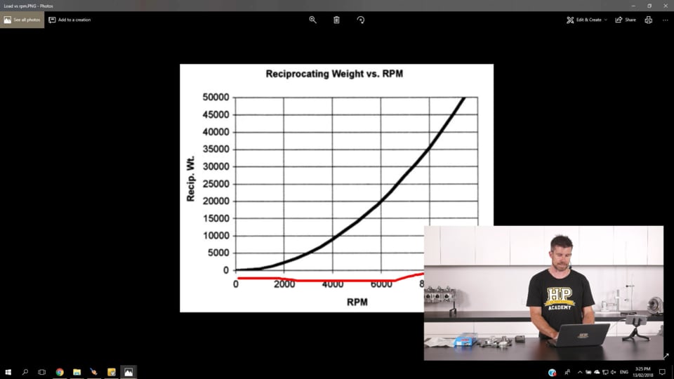
| 08:14 | So just to have a quick look at how that looks, if we jump across to my laptop screen, this is just a graph taken from ARP's website, and on our vertical axis here we have our reciprocating weight of our piston and conrod assembly. |
| 08:29 | So this is just a generic mass for reciprocating weight for a given mass of piston and conrod and stroke of the crankshaft. |
| 08:38 | And we can see on our x axis here, we have our engine RPM. |
| 08:41 | So this is something that I think a lot of enthusiasts and even somewhat knowledgeable engine builders tend to overlook, if we look at what happens here at 6000 RPM. |
| 08:52 | we've got a reciprocating weight of about 20000 pounds. |
| 08:55 | If we go from 6000 to 8000 RPM, that actually jumps up to 35000ths, so it's a massive, a really significant increase in our loading on our connecting rod bolts for what is still a relatively modest increase in our engine RPM. |
| 09:11 | So this is one of the main factors that we need to really take into account. |
| 09:15 | If we are planning on increasing our engine RPM limit significantly above stock, then this is gonna have a really big impact on the required strength of our connecting rod bolt material. |
| 09:28 | Alright I'll just head back across to my notes for a second. |
| 09:36 | What we need to take into account here then obviously is our RPM. |
| 09:39 | And this is our main driving factor here. |
| 09:43 | And obviously now we can hopefully understand that the amount of power that the engine's making becomes much less important, it's really secondary to that engine RPM. |
| 09:53 | What we need to be able to achieve is an amount of preload on our conrod bolts that is always in excess of the tensile forces being applied to the conrod bolts when the piston goes past top dead centre on the exhaust stroke. |
| 10:10 | Now if we can't exceed the tensile forces being applied to those conrod bolts, what's going to happen is during that point, those conrod bolts will be stretched further and this in time will result in a fatigue failure of the bolts. |
| 10:27 | It's also important here that we keep a margin of safety in operation. |
| 10:33 | So for example ARP recommend that a margin of safety of around about two times is kept in mind there when we are choosing the bolts. |
| 10:43 | We want to make sure that we're well and truely above the maximum load that is going to be applied to those bolts in order to make sure that they're not going to fail. |
| 10:53 | Now while the main load, the main force that's being applied to our connecting rod bolts is in tension, another aspect that is often overlooked, and this does now somewhat have a relationship to our power, is that the conrod is going to flex and distort, even though we've got in this case a good quality steel connecting rod, what's going to happen is that the big end journal of the connecting rod is going to distort marginally, it is going to flex marginally. |
| 11:22 | And particularly if it flexes across the junction between the main body of the conrod and the cap, what we're going to end up doing is applying some amount of bending load into our connecting rod bolts as well so this is another reason why ARP recommend a margin of safety there of two times. |
| 11:43 | OK so as well as the material of the connecting rod bolt, we also need to take into account the rod bolt diameter. |
| 11:50 | Now this part often is outside of our control. |
| 11:54 | We're going to find that the rod will be designed with the likely tensile forces in mind. |
| 12:01 | So particularly if we're looking at an aftermarket connecting rod like this, as we've explained, Brian Crower recommend these rods for a certain power rating. |
| 12:11 | So the whole rod as well as the original fasteners that are supplied with the rod, are sort of designed with that in mind. |
| 12:19 | Common sizes for our connecting rod bolts include a 3/8th inch and a 7/16th inch thread. |
| 12:26 | Now that does refer to the diameter of the thread for our connecting rod bolts. |
| 12:31 | And what we may find there is that while obviously Increasing the diameter of our connecting rod bolt is going to improve its strength, we may find that with a connecting rod in particular, this simply isn't possible. |
| 12:46 | If we look at the size of our connecting rod here, there's a minimal amount of material through the body of the connecting rod where that rod bolt goes. |
| 12:55 | So if we were to have the thread machined out to 7/16th, we're going to find that while yes, our connecting rod bolt may now be stronger, we're going to actually end up reducing the strength of the connecting rod itself and while we've got a stronger rod bolt we're actually probably going to end up with a weaker overall conrod that's more likely to fail. |
| 13:18 | When we are talking about our rod bolts as well, as I've mentioned there, the diameter refers to the thread. |
| 13:26 | And what we actually find is through the body of the conrod bolt, let's just go to our remote camera here. |
| 13:34 | If we look at the design of our conrod bolt, we actually see that it necks down in diameter through the centre of the fastener. |
| 13:43 | And the reason for this is it's designed to reduce any chance of stress raises in our connecting rod bolt. |
| 13:52 | In particular basically if this wasn't necked down, the weakest part of the connecting rod bolt would be the root diameter of our top thread and this would be where we'd expect the conrod bolt to fail. |
| 14:05 | So by necking down the main part of our connecting rod bolt here this reduces, or evens out, equalises the stresses in the rod bolt and prevents a failure on that diameter root thread of the rod bolt. |
| 14:25 | When we are looking at upgrading rod bolt fasteners, the two measurements that you will need to know so that you can order replacement parts, one is that thread diameter, the other key measurement is the under head length. |
| 14:39 | So as it's name implies, simply the length from the underside of the head to the end of the rod bolt. |
| 14:46 | There's a few different lengths there depending on what size of conrod you're dealing with, so you'll need to measure that and check what you're actually dealing with. |
| 14:56 | So in terms of the materials here, I'm just going to again talk in terms of ARP's products. |
| 15:02 | So every rod bolt manufacturer, every fastener manufacturer, has their own range of alloys that they use for making these fasteners. |
| 15:12 | And everyone has their own specification, their own name for the alloys that they're using, so what ARP produce won't be available necessarily in another manufacturer's range, but they will cross over likely to another name. |
| 15:30 | So for example in the ARP range their generic base model product or base model material is their ARP 2000 rod bolt material. |
| 15:40 | Again if we can just jump across to our remote camera. |
| 15:43 | Hopefully we'll be able to see that that's actually stamped on the head of the rod bolt there, we've got ARP 2000. |
| 15:50 | So this refers simply to the material that has been used for the manufacture of that bolt. |
| 15:56 | Off the top of my head I think the ARP 2000 material has a tensile strength of 200000psi. |
| 16:04 | Now if that's not going to be sufficient for your task, there's a few different options in the ARP range. |
| 16:11 | The next common upgrade is to move to ARP's L19 material. |
| 16:17 | This is the equivalent of an H11 tool steel. |
| 16:21 | I think from the top of my head these come up to about 240000 or 250000 psi. |
| 16:27 | So again the marking there is on the head of the rod bolt. |
| 16:33 | This one has also taken a nasty knock as you can see which is why it is now surplus to requirements. |
| 16:39 | But we've got L19 stamped on the top of that rod bolt head. |
| 16:44 | Now while i am actually handling this with my bare fingers, one important aspect to take into account if you are using ARP's L19 material, is that this is a no no, we want to be really careful when we are handling the L19 material as it does suffer from hydrogen embrittlement. |
| 17:04 | So what we wanna do when we are using L19 material is we want to use a set of gloves so that we make sure that the oils from our hands don't end up damaging those rod bolts. |
| 17:18 | The only reason I'm handling these by hand is because they are out of a broken conrod, a damaged conrod and they're never going to see service again. |
| 17:26 | So that's a tip that again a lot of people don't understand or completely overlook with that L19 material, we do need to be very careful with the handling of it. |
| 17:36 | The highest level of material in the ARP rod bolt range is their Custom Age 625 material. |
| 17:44 | So again this just increases further the tensile strength of the material. |
| 17:49 | Just providing an increase in safety margin again over their L19 and over their ARP 2000. |
| 17:55 | So of course the downside with these better grade of materials is understandably you're going to be paying a lot more money for them. |
| 18:06 | So it pays to have an understanding of what each particular material is suitable for and understand when we may need to upgrade to a stronger material. |
| 18:20 | So while we can here go through a calculation and basically look at some engineering equations for calculating the acceleration, calculating the mass of the components, and actually calculating directly the force being applied to those conrod bolts, in general I find at the hobbyist level of the market, this isn't something that most of us are going to go through. |
| 18:47 | The other thing I find, in the hobbyist level of the market, is we're generally not creating engines that are designed to break any world records. |
| 18:56 | So when we are looking at mild or even moderate improvements in performance from our engine, often it's not actually necessary to really overthink these selections and if we have some broad rules of thumb in mind, this is usually sufficient to get us a product that is going to last. |
| 19:14 | I'll say right now though that if you are listening to this webinar and you're aiming to build something that really is completely out of left field with what the base engine components were designed for, then ARP's technical helpline is excellent. |
| 19:29 | You can ring up their technical helpline, tell them exactly what your application is, give them information such as your piston weight, your conrod weight, your crankshaft stroke, and your maximum expected engine RPM and they will be able to come back to you with information on exactly which of their products is going to be suitable. |
| 19:48 | I will mention that while I am using ARP for today's example, of course this crosses over to any of the mainstream fastener manufacturers, they're all going to be able to provide you with the same level of help. |
| 20:01 | So our engine builds, I generally find, fall into three categories. |
| 20:05 | So the first category I would class as a mild upgrade where we're taking a stock engine, we're looking at a power increase of maybe in the region of 20%, maybe 25% and we're going to be using the stock rev limit or we might be increasing the rev limit by somewhere in the region of 500 RPM. |
| 20:26 | Now under these conditions, even ARP's base fastener, the ARP 2000 is going to be more than adequate for our task. |
| 20:34 | What we'll also often find, which again is an area that's often kind of ignored or overlooked is when we move from a factory cast piston and a factory connecting rod, particularly some of the later model connecting rods which we're seeing in our current crop of performance engines, some of these factory connecting rods are very very light and very very small. |
| 20:56 | Often when we move to a performance based H-beam or I-beam forged conrod, and an aftermarket forged piston, we actually find that we will increase the mass of these components compared to what we had stock. |
| 21:10 | So remembering that the mass of those components coupled with our engine RPM and the stroke, all goes hand in hand to increase the amount of stress being applied to the rod bolts. |
| 21:20 | This is something that we do need to take into account. |
| 21:22 | So if we're looking for a mild upgrade then I would not hesitate to just simply use the base ARP 2000 rod bolt. |
| 21:31 | When we're looking for a more significant increase in power and engine RPM, this is where we may start to look at the better grades of fasteners. |
| 21:42 | So one of the examples here I'm going to give is from our 4G63 race program. |
| 21:47 | We build a number of 4G63 engines for both circuit racing and drag racing applications. |
| 21:53 | In a stock form the Mitsubishi 4G63 has a 7500 RPM rev limit. |
| 22:00 | Remembering that the stress being placed on the conrod bolts increases with the square of our engine RPM. |
| 22:06 | We know that any increases in our engine RPM are going to have a significant effect on the stress in the conrod bolt. |
| 22:13 | With a typical circuit racing engine, we would take those engines from around about 300 horsepower up to 500 to 600 horsepower and generally extend the rev limit between 8000 and 8500 RPM. |
| 22:25 | Now at that point the ARP 2000 rod bolt for long term reliability can become quite marginal. |
| 22:33 | What we'll find though is that the rod bolt itself won't necessarily fail straight away. |
| 22:40 | We're still operating below the ultimate tensile strength of the conrod bolt. |
| 22:46 | But what we do open ourselves up to now is a reduction in the fatigue life of the rod bolt. |
| 22:52 | You'll remember that I said under high loads, under high stress, high power, high RPM operation, that the conrod itself will flex, we're going to see some distortion in the conrod, this puts a bending force into the conrod bolts which also increases the amount of stress being placed in the rod bolts, and if we're starting to operate anywhere near the ultimate strength of that rod bolt, the ultimate tensile strength, the over time can result in the rod bolt failing. |
| 23:20 | So in this case I'd definitely be more inclined to step up to the stronger L19 rod bolts. |
| 23:27 | It is a relatively minor increase in expense. |
| 23:30 | And of course we only need to have one rod bolt fail and that's going to end up costing us the entire engine. |
| 23:36 | So in my opinion, it is a cheap insurance program. |
| 23:40 | Lastly the more extreme engines would be actually something where we are often looking at a massive increase in the engine RPM limit. |
| 23:51 | So again with our very high level drag 4G63s we took the engine rev limit from 7500 RPM, in our own engine we were shifting at 10500 RPM, we actually had a rev limit set at 11000 RPM. |
| 24:06 | So again just remembering back to our chart of the reciprocating mass versus our engine RPM, we're really starting to see a massive increase there. |
| 24:17 | Two things that come into account there, one which is really outside of the scope of today's webinar is anything we can do at this point to reduce the reciprocating mass of our components is going to definitely help. |
| 24:30 | So anything we can do to reduce our piston mass as well as anything we can do to reduce our conrod weight, this is why we often see in high RPM drag engines, the use of an aluminium conrod. |
| 24:41 | This reduces that reciprocating weight quite nicely. |
| 24:46 | But at this point we need everything going for us, everything in our favour that we can from our rod bolts so this is where we would be looking at stepping up to something like the ARP Custom Age 625. |
| 24:58 | Now we're talking here about very high powered drag engines. |
| 25:02 | in particular our little two litre 4G63s were producing somewhere in the region of 1200 to 1300 horsepower. |
| 25:09 | But remembering that the power really isn't the important factor here. |
| 25:14 | This is another consideration that we would also need to take into account if we're building an all out naturally aspirated engine that's going to be exceeding the factory rev limit by a similar amount. |
| 25:28 | So for example it's not uncommon to take something like the Toyota 4AGE which again in stock form has a rev limit somewhere in the region of about 7000 RPM, 7500 RPM. |
| 25:40 | And one of the common uses in race applications for that engine was in the old Formula Atlantic series. |
| 25:46 | In that case they were taking that engine out to produce around about 240 fly wheel horsepower and that engine was revving to 10500, 11000 RPM. |
| 25:57 | So again it's the RPM that's the problem there. |
| 25:59 | Even though we've got a relatively short stroke engine in the 4AGE we are now massively increasing our engine RPM so again we would want to step up to the strongest rod bolts that we can. |
| 26:13 | So if we break our engine applications down into those three realms, this, for 90% of you out there in the hobbyist market is going to be enough guidance. |
| 26:22 | And again if you are outside of those regions then of course I would recommend that you deal directly with the manufacturer and get some technical support from them so you know that you're choosing exactly the right fastener. |
| 26:36 | OK so we've talked about rod bolts, but one more thing that again just gets a little bit outside of the scope of our webinar, there is another webinar that we did that you can check out in our archive on the correct way to torque down fasteners, the correct way to tighten fasteners. |
| 26:52 | But particularly with the rod bolts what I want to just discuss here is the correct options there. |
| 26:58 | So when we are tightening any fastener using a torque wrench, what we're actually trying to do is create the correct amount of stretch in that fastener. |
| 27:09 | You can think of the rod bolts or any of our fasteners essentially as little really stiff springs, and what we're trying to do is just stretch that fastener a little bit, and it's the stretch in that fastener that provides the clamp. |
| 27:21 | And we want to get exactly the right amount of stretch in order to provide optimal clamp. |
| 27:26 | If we don't go far enough we're not going to achieve the manufacturer's recommended clamping force. |
| 27:31 | If we go too far of course we risk stretching the fastener and actually reducing its effectiveness. |
| 27:38 | So particularly with a conrod bolt where we do have the ability to access both sides of the rod bolt, it's not in a blind installation. |
| 27:47 | Rather than using a torque wrench and tightening the rod bolt to a specific torque, we have the option instead of measuring the stretch. |
| 27:57 | And we can do that using a conrod bolt stretch gauge which looks a little bit like this. |
| 28:02 | So what I'll do is we'll just swap over to our remote camera here and hopefully I'll be able to get this in here. |
| 28:09 | So what we have is a dial gauge on the end of our rod bolt stretch gauge and we can just locate our conrod bolt in our stretch gauge. |
| 28:18 | And there are little dimples in both ends of our conrod bolt particularly for locating in a stretch gauge like this. |
| 28:26 | And you can see at the moment we've essentially got our dual gauge zeroed. |
| 28:30 | So what we can do, we can fit our stretch gauge once the rod bolt is fitted into the connecting rod. |
| 28:37 | And we can use this, coupled with our torque wrench, so actually measure the amount of stretch in the rod bolt as we tighten it down. |
| 28:44 | In this particular instance with our ARP 2000 rod bolt, our 3/8th fastener, we're actually looking for a stretch in the order of about 4.5 to 5.5 thousandths of an inch. |
| 28:55 | So with this particular product, what we can do is A, ensure that we're getting exactly the correct amount of stretch in that fastener, and B we can sort of use it to calibrate if you like our torque wrench. |
| 29:09 | So we can find out, rather than just going to a specific torque rating of maybe 45 foot pound, we can actually find out if maybe our particular torque wrench requires 46 or 48, or maybe 43 foot pound to get to that recommended stretch. |
| 29:27 | The other thing that goes hand in hand with torquing down these fasteners or tightening down these fasteners and getting the best results from them, is to use the manufacturer's recommended lubricant. |
| 29:38 | So in this case we've got a lubricant from Carillo. |
| 29:42 | We've also got another lubricant from A1 Technologies. |
| 29:45 | There will be differences between these lubricants but essentially what we're trying to do there is reduce the friction between the threads in the rod bolt and the conrod, and we're also trying to ensure that we get repeatable results when we are torquing those fasteners down. |
| 30:02 | OK so we've covered the rod bolts there in a little bit of detail but again they are the most important fastener in my opinion inside the engine. |
| 30:09 | So it's something that we do need to keep in mind and really it's worth giving them a lot of thought. |
| 30:17 | We'll move on now, we're going to deal with our main bearing fasteners. |
| 30:25 | So obviously in a stock engine these are typically going to be a bolt. |
| 30:30 | And when we're building a performance engine and we're swapping these bolts out for aftermarket fasteners, most often we're going to be replacing them with a stud kit. |
| 30:40 | Now what we need to do here is going to be very dependent on our engine. |
| 30:45 | And in most instances we tend to find that the engines, most of the factory performance engines that we are dealing with these days are generally over engineered from stock and hence in most instances we'll be able to fit a simple off the shelf stud kit and replace the factory bolts and we won't have to think anything more of it. |
| 31:07 | Now there are a couple of caveates here, or considerations that we do need to keep in mind. |
| 31:12 | Firstly, any time we're replacing the factory main bearing cap fasteners, what we're trying to do, if we go from a stock bolt to an aftermarket stud kit for example, again just like our rod bolts, we're providing material that is superior, that's stronger and can provide additional clamping. |
| 31:29 | Now the problem with this is that in some instances, that additional clamping, while it can be beneficial, it can do a better job of holding all of our components together, we may also find that it can actually distort the main bearing journals in our crankshaft. |
| 31:45 | So in other words what we're doing is tightening everything down so tightly that the journal is actually distorted and it's no longer perfectly round, so this affects our bearing clearances, it can affect the crush on our bearings. |
| 31:58 | And if we don't do anything about this, we can end up with reliability problems through a lack of lubrication to our main bearing journals on our crankshaft. |
| 32:07 | This tends to be more of a problem if we are dealing with an aluminium block. |
| 32:12 | The aluminium block being a little bit more fragile I guess than a cast iron block. |
| 32:18 | But particularly if you are dealing with an aluminium block, it is a really good idea to measure your bearing journals with those new studs torqued down, torqued into place. |
| 32:29 | And if there is any eccentricity in your journals, then you'll need to have your machinist perform a line honing process on that to correct them and bring all of your journals back to being perfectly round. |
| 32:43 | If you don't do that, if it's something you overlook, then you actually risk the chance of ending up with superior clamping, but end up actually damaging your engine due to the lack of lubrication on your bearings. |
| 32:56 | Now how do you know that you are suffering from a problem where you don't have enough clamping force on your main bearings? Well one of the keys is that when we dissasemble the engine, one of the first things we look at, we've got here a factory main bearing cap from a Toyota 1FZ FE engine. |
| 33:16 | This particular cap has never actually been used. |
| 33:19 | But what we are looking for when we disassemble the engine is any sign of fretting on the surfaces where the main bearing cap contacts the block. |
| 33:28 | Let's just go across to our remote camera and we'll have a look at this in a little bit more detail. |
| 33:33 | Again this one hasn't been used, all we've got here visible is the actual machining marks which is what we'd expect to see. |
| 33:40 | When we talk about fretting, what we're going to see instead of these nice clean machining marks, is we're going to see pitting. |
| 33:45 | And we'll actually see a transfer of material from the engine block to the cap and vice versa. |
| 33:51 | So you're going to end up with a surface there that almost looks a little bit like sandpaper in locations. |
| 33:57 | Now the reason for that, the reason that you're seeing that appearance, is because under the high loads of high RPM, high power operation, what we're actually seeing is the bearing cap is being forced slightly off the engine block. |
| 34:13 | It's actually flexing off the engine block, and this allows that cap to essentially move around and hence we get that transfer of material from the engine block to the bearing cap. |
| 34:23 | So while this is also moving around, obviously this is affecting our bearing clearances, where as we flex it's opening up our bearing clearances, we may end up losing oil pressure and this will also affect the film strength of the oil on our bearing so again it can result in a reduction in our film strength, our oil strength, and result in damage to our bearing surface and our crankshaft journal. |
| 34:49 | So obviously none of these things we want happening. |
| 34:51 | The other thing is over long term occurrence of this fretting, when we pull our engine down, and we put it back together, we find that our bearing caps no longer locate perfectly, if we don't get them back exactly where they were, this will also affect the static clearance, in terms of oil clearance that we've got when we put these things back together. |
| 35:11 | So this is one of the key thing that we do need to look for when we're disassembling an engine to decide whether the fasteners that we are using are up to the task. |
| 35:20 | Now of course in a lot of our modern engines, particularly some of the V8 engines that use four bolt and six bolt mains, they really are very rigid in this department and it isn't an issue. |
| 35:31 | Again just bringing back to the 4G63 drag program that we ran, this sort of issue wasn't a problem when we were running in the 500 to 600 horsepower vicinity. |
| 35:43 | Once we stepped up past the 800 to 1000 horsepower vicinity and particularly with that high RPM, this was a serious problem. |
| 35:51 | In our own engines we tried a few variations there to address this, the stock fastener for the 4G63 is a 10 millimetre fastener and we actually stepped that up. |
| 36:04 | We tried machining the block out to take an 11 mil fastener. |
| 36:08 | And this really comes back to what I was talking about with the connecting rods. |
| 36:13 | While on paper that all looked like a good option, we found that the first time we took that car to the drag strip the block actually cracked through those fasteners, through the main bearing caps. |
| 36:27 | And basically the entire block failed. |
| 36:29 | We're actually really lucky that the engine didn't completely fall to pieces as it was going down the drag strip. |
| 36:35 | What we ended up doing was the block essentially cracked and allowed one of the balance shaft bearings to pop out which in turn resulted in an internal oil leak inside the engine. |
| 36:46 | So this brought on an oil pressure warning light, so allowed me to shut down the engine before any serious damage was done. |
| 36:55 | But when we actually pulled the engine apart it was quite spectacular, it had cracked through just about every journal inside the engine block. |
| 37:03 | So the final solution we went to there is instead of using the base ARP 2000 material, we did step up and we had some custom fasteners made in an H11 tool steel and that fixed our problem, it reduced that fretting that we were seeing. |
| 37:20 | OK we're going to move into questions soon, I see we do already have a few in there which is great. |
| 37:24 | Before we move onto that, the last fastener that I wanna talk about here is the head studs. |
| 37:30 | So these are responsible for clamping the cylinder head down to the engine block. |
| 37:36 | So again if we're looking at mild upgrades to our engine, an off the shelf stud kit is probably going to be sufficient for most people. |
| 37:47 | These replace the factory bolts, just like our main stud kit. |
| 37:50 | Replaces the factory bolts with an aftermarket stud kit. |
| 37:54 | We've got here an ARP stud kit for a Honda B18C. |
| 38:00 | So this is our factory bolt, pretty typical. |
| 38:02 | Often we'll also find that the factory head bolts are a torque to yield fastener which means that they are a one use fastener. |
| 38:11 | We are torquing them past the yield point so they are permanently deformed after they're stretched. |
| 38:16 | If you aren't sure if the fastener you're dealing with is a torque to yield fastener, your workshop manual will state that they are not reusable and you'll also find that the torquing process involves torquing all of the fasteners down to a specific torque and then torquing them down further or tightening them further I should say to a specific angle. |
| 38:39 | So if you're using something that uses a torque angle method then that is a torque to yield fastener and it isn't reusable. |
| 38:45 | So on the other hand we've got our ARP stud kit here which includes a stud, a washer and a nut. |
| 38:53 | So these are torqued below the yield point and hence they are reusable, they aren't going to be permanently deformed. |
| 39:02 | And again they also provide a significant increase in clamp force over those factory bolts. |
| 39:09 | So this really comes down to our head gasket sealing, and what we need here is going to be very dependent on the type of engine that you're dealing with. |
| 39:17 | If you're fortunate enough to be dealing with a naturally aspirated engine then your task generally is much easier because the ultimate cylinder pressures in a naturally aspirated engine are always going to be relatively limited and hence it's normally not too much of a challenge to clamp the head down correctly and maintain a good seal between the head and the head gasket. |
| 39:41 | Our real challenge with our head studs comes down to forced induction engines, and again particularly if we are looking at very high boost pressures in a forced induction engine, and again I'll just hark back to our experience with our 4G63 drag program, we started out using the base model ARP 2000 head stud kit. |
| 40:02 | Again this is fine in a mildly modified format. |
| 40:06 | We would probably quite capably run those engines up to maybe 500 even 600 horsepower using that sort of stud. |
| 40:16 | Once we go past that we find that head gasket reliability can become problematic and at that point I'd be more inclined to step up to the ARP L19 head stud kit. |
| 40:28 | Those ARP L19 head studs coupled with a quality multi layer steel head gasket, generally were good up to maybe 800, 900 horsepower. |
| 40:38 | Beyond that we start getting back to the same problem with the head gasket sealing becoming marginal. |
| 40:44 | So one of the solutions we went to there was to actually machine the block out to step up the size of the head bolts, or head studs. |
| 40:54 | So in the later model 4G63s, the stock head fastener is an 11 by 1.25 millimetre fastener. |
| 41:02 | We stepped that up and went to a half inch fastener. |
| 41:05 | So this does require some specialist machining. |
| 41:08 | You can't do this with a drill and a tap set I'll assure you that. |
| 41:13 | It really does need to be done very accurately to make sure that your new threads are drilled and tapped concentric to the existing threads. |
| 41:24 | And we also want to make sure that everything is exactly where the original fasteners were. |
| 41:30 | If we don't do that we're gonna have a lot of trouble getting our cylinder head bolted down. |
| 41:35 | We also may end up having problems with the threads actually pulling out of the block which obviously could be a pretty devastating situation. |
| 41:44 | So by stepping up to a half inch stud, again with a superior material, that lets us push past that sort of 1000 horsepower mark from a two litre 4G63 engine. |
| 41:53 | At which point we generally are pushing somewhere in the region of 45 to 55 plus psi of boost. |
| 42:01 | Consider if you are going to be increasing the diameter of your head studs, this again does come with some downsides. |
| 42:10 | We're also going to need to increase the size of the holes through the cylinder head so that our new fasteners will fit. |
| 42:17 | Often if we're going really large as well, we're going to need to consider the dowels that locate the cylinder head to the engine block. |
| 42:26 | This wasn't an issue with our 4G63, we were only stepping up from, essentially one millimetre in diameter, we're going from 11 mil to 12 or 12.5 millimetre. |
| 42:36 | But particularly in the Subaru tuning world, it isn't uncommon to step up to a 14 mil stud. |
| 42:44 | And with a 14 mil stud, let's just jump across to my laptop screen for a moment, this is our Subaru FA20 engine. |
| 42:53 | We haven't quite gone to 14 mil studs here but it shows you the points that I wanna talk about here. |
| 42:59 | First of all we are going to definitely wanna make sure that we are torque plate boring and honing that block to make sure that the distortion that we're going to get from the clamping force on those larger fasteners doesn't result in our bores being out of round, so that's one aspect. |
| 43:16 | The other aspect that we can't quite see in this particular photo is that when we're going to a 14 mil stud on the Subaru engines we do need to machine the block and also the cylinder head for larger diameter dowel. |
| 43:30 | So again this is a task that needs to be done really carefully, the alignment of those dowels versus the block and the cylinder head needs to be perfect, otherwise we're going to find that we can't bolt the cylinder head down or the cylinder head is going to be marginally offset in relation to the bores. |
| 43:47 | So there are a few things to keep in mind there. |
| 43:50 | Alright I'll head back across to my notes now. |
| 43:53 | OK so that's taken us to the end of our webinar, hopefully you've got a better understanding now of how the fasteners affect the reliability of our engine, hopefully a little bit of a better understanding of what materials are available and when a particular material might be more suitable for your specific application. |
| 44:13 | We'll move into some questions now. |
| 44:15 | And if you do have any further questions, please ask them and I'll try and answer them. |
| 44:22 | Craig W has asked does the grain structure start to change as the RPM increases? No I'll admit right now I am no metallurgist, but the grain structure is an aspect of the material in the way the fastener is constructed, we're not going to actually change the grain structure inside the fastener while the engine is running. |
| 44:44 | Actually one thing I will just mention here, slightly off track from Craig's question but something I should've mentioned as well. |
| 44:51 | Is when it comes to the fasteners we are using, the threads or more specifically the root of the threads which I kind of touched on earlier, are basically the most stressed part of these fasteners. |
| 45:04 | So there is a couple of techniques that are used for forming the threads on these fasteners. |
| 45:11 | One of them is a technique called hot rolling, which as it's name implies, the threads are actually cut, sorry cutting the threads is what I wanted to say there. |
| 45:22 | This is where the threads are physically cut, in the same way we would use a die to cut threads onto a piece of steel bar. |
| 45:31 | Now that's going to end up definitely producing stress raises at the root of each of those threads. |
| 45:37 | So the preferred technique of forming threads on a performance fastener is what's referred to as cold rolling. |
| 45:44 | And this is performed after the heat treatment on the fastener is completed. |
| 45:49 | And instead of a cutting tool, the threads as the name implies are actually rolled. |
| 45:54 | It requires a lot more force as you could understand. |
| 45:58 | But what it does is it retains the grain structure in the root of the thread and provides a better grain structure around that root and reduces the stress raises that you're going to get from cutting the thread. |
| 46:12 | So this isn't much of a concern because all of the quality fastener manufacturers will be cold rolling their threads. |
| 46:19 | But it is something that is worth discussing there as well. |
| 46:26 | Barry's asked, when upgrading a rod bolt, do you have to take into account the extra torque deforming the big end of the rod. |
| 46:33 | Yeah Barry that's actually something I should've mentioned. |
| 46:36 | And just exactly like I talked about with the main bearing journal in our engine block. |
| 46:41 | If we do go from a rod that's fitted with ARP 2000 rod bolts and we maybe step up to L19 or Custom Age 625, because we are putting a lot more clamp loading into the conrod itself, this can in turn distort the big end journal. |
| 46:59 | So we want to definitely measure that. |
| 47:03 | In production we'll find that the finished journal is honed with the conrod bolts fitted and torqued to specification. |
| 47:12 | So if we find that the conrod journal is no longer perfectly round, then we will have to have that conrod resized. |
| 47:20 | This is a task that you can leave to your engine machinist, we're certainly not going to be able to hone the big end bearing of our conrods as a home enthusiast. |
| 47:30 | So if you are considering upgrading your rod bolts, this is something you want to do in conjunction with the machining process. |
| 47:36 | Unless you have access to a dial bore gauge where you can actually check the bore diameter of your conrod yourself. |
| 47:45 | Matt's asked, what are the differences between common materials like ARP 2000, 8740 and 625 plus? Just more clamping force as you spend more money. |
| 47:55 | Yeah so in terms of the ultimate tensile strength, ARP 2000 and 8740 are both very very similar. |
| 48:03 | Then L19 and Custom Age 625 plus, yes we're just providing a stronger material that has the ability to produce stronger clamping force. |
| 48:13 | There are also differences in those materials which I haven't gone into in terms of their fatigue life as well so again from the more expensive materials like Custom Age 625, we do get an improvement in the fatigue life of that material. |
| 48:30 | That works in conjunction though with how closely we are operating to the ultimate tensile strength of that particular material. |
| 48:36 | Or actually more specifically the yield strength of that material. |
| 48:41 | If we're operating very close to the yield strength of the material then that's going to have that material fatigue much more quickly than a fastener where we've got a larger margin of safety and we're operating nowhere near the yield strength of that particular material. |
| 49:00 | Barry's asked, do you use your rod stretch gauge on the bench or do you measure the stretch while the rod is in the motor? The reason for asking is that it's extremely hard to get the rod stretch gauge on the rod bolt on some motors when the main cradle is installed. |
| 49:13 | Yeah that's another great question there Barry, and you can, it will depend on your access to the rod bolts. |
| 49:19 | If you've got easy access then there's certainly nothing wrong with measuring the rod bolts installed in the block. |
| 49:26 | But as you've correctly said with cradles on some of these engines it's essentially impossible. |
| 49:30 | So what we can use is the rod bolt stretch gauge simply as I've mentioned before, to essentially perform a calibration on our torque wrench. |
| 49:38 | And we find out for that particular rod bolt, the particular lubricant we're using, exactly what torque we need to apply in order to achieve the manufacturer's recommended clamp. |
| 49:50 | Then we can go about installing our rod bolts and simply use our torque gauge once we've got that calibration done. |
| 49:57 | Connor has asked, any experience with rotary engines? How important is doweling versus studs? I have had a reasonable amount of experience with rotary engines but sadly only from the tuning aspect. |
| 50:09 | Getting into the building of rotary engines is not something that I've done so I can't really give you too much feedback there on the doweling versus studs unfortunately. |
| 50:20 | Don Smith has asked, are conrod studs and nuts ever a more suitable solution? We find that that is an approach that a lot of OE manufacturers use where the rod bolt is part of the main body of the conrod and we assemble the cap onto the conrod and then use a washer and a nut. |
| 50:41 | In a performance application almost always we're going to be exclusively using a bolt instead that is threaded into the main body of the conrod. |
| 50:50 | Trevor has asked, when replacing torque to yield bolts with an upgraded bolt with ARP, is there a formula to determine the proper torque values as to not over torque or under torque. |
| 51:00 | When you purchase an aftermarket fastener from the likes of ARP, it's always going to come with a specification sheet similar to this one here. |
| 51:10 | It's going to give you the part number so you know that you're talking about the right fastener. |
| 51:14 | It's also going to tell you what torque to use. |
| 51:18 | And it's also going to give you some information about the torquing process in terms of stages that you're going to use, as well as the order to torque the fasteners down in. |
| 51:27 | If it doesn't mention the order to torque the fasteners down in, then you'll use the factory torquing order. |
| 51:34 | But yeah you don't have to come up with the actual torque values yourself. |
| 51:40 | Craig has asked, I'm upping the RPM limit on a build. |
| 51:45 | I'm guessing that ARP 2000 will be good enough over stock? Going 1000 RPM more. |
| 51:50 | Without knowing a little bit more about your build in terms of the engine, the stroke, and also the piston and rod weights, I can't really give you too much more information. |
| 52:01 | 1000 RPM would probably be fine in most instances with an ARP 2000, but particularly if you've got a very high mass of piston and conrod, the you might be starting to get marginal. |
| 52:16 | But about 1000 RPM, that's probably about as far as I would be going without stepping up to a better quality of fastener than the ARP 2000. |
| 52:25 | OK that's brought us to the end of our questions. |
| 52:28 | So if you do have any more, our HPA members are welcome to ask those in the forum and I'll answer them there. |


