164 | Degreeing a Camshaft
Summary
The timing of the intake and exhaust valve opening and closing events is critical to the correct operation and reliability of any engine. In this webinar we will discuss the techniques for degreeing a camshaft, discuss what tools you’ll require and perform a practical demonstration of the process.
| 00:00 | - It's Andre from the High Performance Academy, welcome along to another webinar. |
| 00:03 | In this webinar we are going to be looking at the correct way of degreeing a camshaft. |
| 00:09 | Now I know that this is an aspect that a lot of engine builders really struggle with. |
| 00:14 | There's a lot of misinformation about what exactly degreeing a cam actually entails and definitely even more misinformation about the correct ways we can go about performing that degreeing process. |
| 00:26 | So this is going to be essential for anyone who is fitting a set of aftermarket camshafts or an aftermarket cam to their engine. |
| 00:36 | If we want to get the best possible performance out of that cam or in other words have the camshaft function as the cam grinder, cam manufacturer intended, it's essential that we have the cam degreed correctly so that the valve opening and closing events are occurring at the correct point in the engine cycle where the cam manufacturer had intended. |
| 01:02 | Particularly if you are dealing with a large cam profile as well, this is also essential for reliability. |
| 01:09 | Obviously as we open the valves further, and we open them for longer, we can start getting into a situation where clearance between the valves and the piston pockets, the pockets in the crown of the piston, can become minimal. |
| 01:24 | And by making sure that our cam timing is correct, this is going to ensure, or help ensure, that we're not going to run into problems with valve to piston contact. |
| 01:34 | So I think the first point I want to talk about here is that when we use the term cam degreeing or degreeing cams, a lot of people think that that's simply a process of fitting the cams, the crank pulley et cetera, on the manufacturer's timing marks, and the job's done. |
| 01:51 | We also often see people posting in enthusiast forums where they've got an aftermarket set of cams and they've fitted a set of vernier adjustable cam pulleys and they're talking about setting the cams at perhaps plus two and minus three degrees or something of that nature. |
| 02:09 | And they think that this is the process of degreeing the cams. |
| 02:12 | Now the problem with a lot of this, is it assumes that the relationship between the cam pin or dowel, the locating pin in the camshaft, and the lobes ground on that camshaft, are consistent from one set of cams to the other. |
| 02:28 | Of course that's not always the case. |
| 02:30 | And it also assumes that particularly if we're comparing different sets of vernier adjustable cam gears, that the same goes for those. |
| 02:37 | In other words that the degreeing marks on the vernier cam gear and the dowel location in the cam gear are consistent. |
| 02:44 | When it comes to any aspect of engine building, of course making assumptions is generally a pretty bad place to start. |
| 02:52 | So we don't wanna make these assumptions. |
| 02:54 | what we want to do is actually go through and correctly find where the cams are currently opening and closing in the valves, and then we can compare that to the information on the cam manufacturer's card. |
| 03:07 | And we can make any adjustments as required. |
| 03:11 | So in order to go through this process, we are going to need a few pieces of equipment, and none of the equipment that we're going to require is overly expensive and particularly if you are going to be dealing with performance engines on a regular basis, this is a task that you're going to be performing quite regularly so it's definitely a good investment if you are going to be doing this in the future. |
| 03:38 | So the first piece of the puzzle that we're going to require is a degree wheel. |
| 03:44 | So I'll just place our remote camera so we can hopefully see that. |
| 03:49 | So we've got our degree wheel fitted here. |
| 03:51 | This is on our Honda B18C. |
| 03:54 | So this is a Moroso degree wheel, they're available from a huge range of manufacturers, relatively cheap and you can find these easily on the likes of JEGS, Summit, eBay et cetera. |
| 04:10 | One of the tips that I will give when you are in the market for a degree wheel is that it is actually an advantage to get a large diameter degree wheel which we have here. |
| 04:19 | The reason for this is the further we are away from the centre of the degree wheel, the further apart the degree markings become. |
| 04:28 | It's a subtle aspect but this becomes an advantage because it allows us to be a little bit more accurate with our cam degreeing. |
| 04:36 | The other aspect we do need to consider as well is the way the degree wheel is mounted. |
| 04:40 | So in this case, just to speed up the webinar that we're going to be performing here, I've already gone ahead and mounted this to the crankshafts now on our B18C. |
| 04:51 | In order to do this, what we want to do is make sure that our degree wheel is running concentric with the centreline of the crankshaft. |
| 04:58 | What I mean here is we don't want the degree wheel to be offset, this means as we rotate through a full engine revolution, the degree wheel on the outside edge is going to wobble up and down. |
| 05:08 | So we wanna make sure that it's nice and concentric. |
| 05:11 | In this case Moroso provided us with some aluminium spacers that are drilled at different diameters so all we wanna do there is make sure we're using the spacer that is drilled to the same diameter as our crankshaft bolt. |
| 05:26 | In this case for our Honda B18C, the crankshaft bolt has an outside diameter of 14 millimetres. |
| 05:32 | As long as everything's nice and tight there, it's really easy to make sure that that is going to be concentric. |
| 05:37 | The other thing we do want to watch as well, is that the degree wheel isn't going to foul on any of the engine componentry. |
| 05:43 | Pretty easy on our Honda B18C but in some instances we're going to need to actually space that degree wheel out a little bit in order to make sure that we have sufficient clearance. |
| 05:53 | Now if you are dealing with some popular engines, then there are specific degree wheel mounting tools. |
| 06:00 | These are available for example for the GM LS series of V8s. |
| 06:04 | And what these do is locate in the key way on the crankshaft and then we can fit the degree wheel to the front of them, so this makes it nice and easy and there's also a location for a strong arm so that we can then rotate the crankshaft. |
| 06:21 | Now the other component that we've got in shot there is our pointer. |
| 06:27 | So I'll just show you where that is. |
| 06:30 | Hopefully we can see that nice and clearly on our front camera. |
| 06:33 | So there's a variety of ways we can go about making a pointer. |
| 06:37 | These are available again for popular engines, you can but specific pointer kits. |
| 06:41 | They go along with a degree wheel and physically bolt to the engine block or cylinder head in some location. |
| 06:47 | In my instance, and this is the way I've always preferred to do it because it's incredibly cheap, easy to achieve, I'm just using a piece of tig welding, steel welding rod. |
| 06:59 | And this means you can just easily manipulate and bend that piece of welding rod to suit. |
| 07:04 | When you are doing this though, again just to improve our accuracy, hopefully we'll be able to see this. |
| 07:10 | Right on the very end of our welding rod here, I've also sharpened that to a point. |
| 07:16 | So just again allows us to be a little bit more accurate with our timing values. |
| 07:24 | When we are reading the degree pointer as well, the pointer for our degree wheel, and this also comes down to an aspect for our dial indicator which we're going to talk about shortly. |
| 07:36 | We do need to be aware of an aspect that can bring in some error. |
| 07:41 | This is called parallax error. |
| 07:42 | So it's really important when we are viewing these pointers to make sure that we are viewing them directly head on. |
| 07:48 | So let's just swap over to our remote camera here and I'll try and explain the situation here. |
| 07:55 | So here we are head on with our pointer and hopefully you'll be able to see that that is currently showing us that we're pretty damn accurate on TDC. |
| 08:05 | Now if we come across to the side though, now that we're viewing that pointer from the side, you can see that it looks like we're actually closer to about half a degree off. |
| 08:14 | So this is the effect of parallax error and we always want to make sure that we are viewing directly head on. |
| 08:21 | If we're not doing this, it can easily bring in an error and affect our reading. |
| 08:26 | Particularly if we're inconsistent with how we are making those readings. |
| 08:31 | OK so the next aspect we are going to need is a way of measuring the valve motion. |
| 08:37 | Depending on the type of engine we're working with, in this case because we are working on a Honda, a double overhead cam engine, all of the timing that we're going to be measuring here will be the valve timing events. |
| 08:49 | In some instances where we're maybe working on a push rod engine, we may, instead of looking at the valve timing events, we may be looking at the cam lift, or cam timing events. |
| 08:59 | In either regard though we are going to need a dial gauge in order to do this. |
| 09:04 | So I've got a Mitutoyo dial gauge here. |
| 09:06 | This one is an imperial dial gauge. |
| 09:08 | On the top of our B18C engine we've got a metric dial gauge which we'll be able to see in our other shot there. |
| 09:17 | So we've already got that in location, we'll talk a little bit more about that shortly. |
| 09:21 | But regardless, these are available in metric and imperial units. |
| 09:25 | You're going to have to make a choice there or like we've done here, you can purchase one of each. |
| 09:31 | Lot of it here comes down to the sort of cams you are going to be using. |
| 09:36 | A lot of the cams that are coming out of the United States in particular, all of the cam specifications will be in imperial. |
| 09:44 | So we'll be talking about valve timing events of perhaps 50 thou valve lift for example. |
| 09:50 | In this case with the cams that we're using for our Honda B18C, being a Japanese domestic import engine, the cam spec card in this case is actually in metric. |
| 10:01 | So while we can convert between metric and imperial reasonably easily if we simply keep in mind that there are 25.4 millimetres in one inch. |
| 10:11 | In this case just to take out potential for error, make this a little bit clearer, we are using a metric dial indicator to go along with our metric cam specifications. |
| 10:23 | One thing we will need though when we are measuring valve motion is we're going to need a way of extending our dial indicator. |
| 10:31 | So the dial indicator itself generally is going to have a relatively short plunger on it. |
| 10:38 | So this isn't sufficient to get down into the cylinder head in order to actually get onto the retainer or the bucket or whatever we're trying to measure. |
| 10:48 | So we can purchase extensions for our dial indicator. |
| 10:53 | I've got a couple here, we've got a four inch extension, and we've got a two inch extension. |
| 10:59 | And these can just be wound into the end of the dial indicator or we can also double them up to provide additional extension. |
| 11:07 | So this is going to be something we're going to want to purchase when we are buying our dial indicator, just to make sure that we can in fact get down on top of the retainer or whatever we're trying to measure. |
| 11:20 | Now the dial indicator on its own is not going to be a lot of use, we also need a way of really rigidly mounting that so it's going to be easy to manipulate it so that we can get the dial indicator exactly where we want it. |
| 11:33 | And in this case what we're using is a magnetic base. |
| 11:36 | So if we can just jump again off to our overhead camera and our magnetic base you can see most of that in shot here. |
| 11:44 | As its name implies, it uses a magnet to locate the base securely and then we've got a range of adjustable arms so we can easily manipulate the dial indicator until it's exactly where we need it to be. |
| 11:58 | One of the real big keys here, and I can't go through this process without making this webinar incredibly long, but one of the keys when we are mounting our dial indicator using our magnetic base, is to ensure that the dial indicator is aligned directly in line with the angle of operation of the valve. |
| 12:17 | So this is an easy mistake to make, to have the dial indicator on a bit of an angle where it's contacting the valve retainer and this is going to affect the accuracy of our results. |
| 12:28 | In some instances this is also going to end up with the dial indicator or the extension actually slipping off the retainer as we go through the valve motion. |
| 12:35 | So that's essential. |
| 12:37 | This can be really tricky in some instances as well and a lot of the overhead cam engines, particularly those that use a direct bucket actuation where the cam lobe runs directly on top of a bucket. |
| 12:50 | There's not a lot of room to get down in there and contact the top of that bucket without ending up with the extension or the dial gauge actually fouling on the side of the cam lobe. |
| 13:01 | So it can be a little bit tricky, it's a little time consuming to get that set up, but it is an essential step. |
| 13:07 | Now the other thing we're going to need if we're dealing with an aluminium engine is the fact that the magnetic base is not going to be much use on an aluminium cylinder head or an aluminium engine block. |
| 13:19 | It's obviously not going to work because it needs a ferrous material in order to actually stick to it. |
| 13:28 | Easy solution, again if we can just jump to our overhead shot here. |
| 13:32 | All I've got here is a steel plate, it's about a quarter inch thick, and this is just a piece of scrap steel. |
| 13:39 | And all I do with this steel plate is drill some holes in it so that it can be attached to whatever I'm working with. |
| 13:46 | In this case we can see that I've attached it to a couple of the cam caps on our B18C cylinder head. |
| 13:52 | And we can drill further holes in this to suit whatever engine we happen to be working with. |
| 13:57 | So it just is a nice easy way of providing a secure base to mount our magnetic base to. |
| 14:07 | OK so one of the other tools we're going to need, and we'll go through this process shortly, we're going to need a way of providing a positive stop to the piston so that we can find top dead centre. |
| 14:19 | So there are a few ways of doing this and it's going to depend to a degree if you are working on an engine that is a push rod engine and you're going to be degreeing the cam based off cam timing events as opposed to valve timing events. |
| 14:35 | And you can do this with the cylinder head off. |
| 14:37 | In that case what we can do is use a bridge like this. |
| 14:42 | This just provides a stop, we can bolt this down across number one cylinder and we've got an adjustable stop that we can wind down to provide a positive stop for the piston. |
| 14:54 | So the principle behind this is what we're trying to do is find an accurate representation of top dead centre. |
| 15:01 | Now it would seem that the simple way of doing this would be simply to wind the engine over until the piston reaches the top of the stroke or TDC and that's top dead centre. |
| 15:11 | Now the problem with this is that we end up with quite a few degrees of crankshaft rotation where the piston is actually dwelling at top dead centre. |
| 15:20 | So it's impossible to be really accurate if we are bringing the piston right up to TDC. |
| 15:26 | So what we instead want to do is actually stop the piston a few degrees back from TDC, and then what we want to do is wind the engine over and come back up against that stop, don't worry about this too much because you'll see it in action really shortly, and what we're going to do is have the piston stop either side of top dead centre. |
| 15:46 | We're going to take note of the markings on our degree wheel at each point and true top dead centre is exactly halfway between those two points. |
| 15:59 | So that's one way we can do it, that's if we are doing this process with the cylinder heads off. |
| 16:06 | In double overhead cam or an overhead cam engine, we're inevitably going to be doing this with the cylinder head on and this gives us a couple of options. |
| 16:14 | We can't use the bridge process, but what we can do is use a positive stop, so that looks a little bit like this. |
| 16:23 | This is an adjustable positive stop, and what it has is the same thread as our spark plug, I think it's 14 mil off the top of my head here for our Honda B18C. |
| 16:32 | It's got an adjustable stop so what we're going to do is wind this down into the plug hole. |
| 16:36 | Then we're going to wind down our adjustable stop until it contacts the top of the piston and we can go through exactly the same process. |
| 16:43 | Now these are available again relatively easily and they're cheap but if you don't have access to one of these, the other way I've done this in the past is to modify a spark plug and to tig weld a small section of steel bar to the end of the spark plug just to extend it down. |
| 17:00 | All we're trying to do here is provide a stop that's going to stop the piston just a little bit down from top dead centre. |
| 17:07 | Now of course the other way that we can go about this is to use a dial gauge on the top of the piston crown and use a couple of extensions again. |
| 17:15 | We can do that down through the spark plug hole, provided that that spark plug hole is directly over the top of the piston. |
| 17:23 | We're going to be doing the same process here because we can't look specifically at top dead centre because of the dwell aspect. |
| 17:32 | What we're going to do is zero our dial gauge where the piston is at the top of the stroke. |
| 17:37 | And then what we're going to be doing is moving the piston down on either side of TDC. |
| 17:42 | A certain amount, let's say for example one millimetre or maybe 50 thou, we'll be looking at those degree markings. |
| 17:50 | OK so with that in mind we're going to go through the steps here of degreeing the intake cam on our Honda B18C. |
| 17:59 | We're going to go through a couple of the key steps. |
| 18:01 | So the first point that we're going to go through is finding true top dead centre. |
| 18:07 | So again this is something that's often overlooked. |
| 18:09 | A lot of people think that the factory timing marks on the engine are sufficient and we can rely on them. |
| 18:15 | I can tell you from experience that the factory timing marks are seldom accurate. |
| 18:20 | They're quite often in the region of two or three degrees out, sometimes even more, and then we can also have situations where a factory harmonic dampener has actually moved in operation and the factory timing marks are massively inaccurate. |
| 18:34 | So because we are really focusing here on being very very accurate, it's essential to know that we have top dead centre accurately located. |
| 18:44 | So let's go through that process here. |
| 18:46 | Now at the moment what I've done is I've fitted the degree wheel to our B18C, let's go to our front camera here, and we've located our pointer here. |
| 18:56 | All I've done is located my pointer in a spare empty bolt hole in the cylinder head. |
| 19:01 | And I've located it pointing at the moment at the TDC mark. |
| 19:05 | Now this at the moment is just based off the factory timing marks. |
| 19:10 | So I'm close but probably not quite right. |
| 19:13 | So what I want to do now is go through the process of actually finding true top dead centre. |
| 19:19 | So let's just set up our iPhone camera here so we can get a better look at this. |
| 19:26 | What I'm going to do first of all is I'm going to turn the engine away from TDC a little bit. |
| 19:32 | So what we wanna do is just turn it maybe about 20 or 30 degrees off TDC. |
| 19:37 | And this is just going to allow me to wind the postive stop down the spark plug hole without it contacting the piston initially. |
| 19:45 | So we can drop that down our spark plug hole and we're just going to wind that down, wanna make sure that this is nice and tight. |
| 19:51 | Another point here for Honda people is that we are degreeing the cam here off the high VTech lobe. |
| 20:01 | So what we've done here before the start of this webinar is we have locked up the VTech mechanism, it's mechanically locked so it is operating solely on the high VTech lobe. |
| 20:12 | OK so with our positive stop wound down now, just gonna bring us back up a little bit closer to TDC. |
| 20:18 | I normally like to do this process relatively close to TDC. |
| 20:22 | So now I can use a screwdriver and I'm just going to gently screw this brass stop down until it contacts the top of the piston. |
| 20:33 | It's really important if you are using one of these positive stops as well, to be very very certain that there's no way that the engine can be turned over on the starter motor while that positive stop is in the engine. |
| 20:44 | Understandably it's going to straight away punch a hole through the top of the piston, it's not going to end well. |
| 20:50 | OK so we've got that wound down now until we are on the top of the piston. |
| 20:55 | So I'm just going to apply a little bit of pressure on the strong arm here and we're going to take note of our degree marking. |
| 21:04 | So in this case we have a degree marking here, we are 10.5 degrees, close enough at least for the purposes of today's webinar, before TDC. |
| 21:14 | And I'm just applying a little bit of pressure here on the strong arm just to make sure that we are loaded against that positive stop. |
| 21:21 | Now what I'm going to do is wind the engine back around the opposite way. |
| 21:25 | I'm gonna come back up on TDC and we'll see what our marking is. |
| 21:29 | When we're coming up on TDC, we want to do this nice and slowly as well, we don't wanna hit that stop too sharply. |
| 21:36 | OK so in this case we have come back up on our stop and we are six degrees there before TDC. |
| 21:44 | So we had 10.5 and we had six degrees. |
| 21:48 | So the way we can go about this is the true TDC, our actual TDC is halfway in between those two marks. |
| 21:56 | What we can do here is we can simply add 10.5 and six degrees, we add our two together. |
| 22:04 | It gives us a total of 16.5 degrees. |
| 22:06 | We want to divide that by two. |
| 22:10 | And that will give us our actual marking, our actual point. |
| 22:15 | So 16.5 divided by two, means that we want to adjust our pointer here so that it's pointing at 8.25 degrees. |
| 22:23 | OK so what we can do, we'll make sure we're still loaded against our stop, and at the moment we're on six, so I just wanna move this two degrees essentially 2.25 degrees across. |
| 22:34 | And this is one of the advantages with these pointers, it's very easy to manipulate it. |
| 22:40 | So we're now on 8.25 degrees and we can just double check our work there by again rotating back the opposite way and coming back on TDC, and we can see that again on this side, hopefully you can see that, we're on 8.25 degrees. |
| 22:57 | So we know that we've now found true TDC. |
| 23:00 | So the process there just to repeat, we're going to stop the piston a little bit down from TDC, we're going to take note of the degree markings on each side of TDC, we want to just add those together and divide them by two. |
| 23:12 | And that's going to tell us where we need to adjust our pointer to in order to find true TDC. |
| 23:18 | So once that process is complete, we can then remove our positive stop out of our engine and again this is going to also make sure that there's no potential for any damage being done there. |
| 23:41 | OK so we've got our positive stop out, so that's our first step of the process there, or one of the most important steps of the process is to find true TDC. |
| 23:49 | If we haven't done that accurately then basically none of the other aspects matter because everything's going to be affected by the TDC marker. |
| 24:03 | OK so what we're going to do now is have a look at our cam spec card so that you can understand what we're actually looking at on that cam spec card. |
| 24:14 | We'll talk about the key points that we need to understand. |
| 24:18 | So in this case we are using a Kelford cam as I've said and our B18C is fitted with a set of blocks of vernier adjustable cam gears. |
| 24:26 | That's what we're actually going to be using for making our cam adjustments. |
| 24:31 | So let's just jump across to our remote camera here, I'll try and align this so that we can look at the different aspects of our cam card. |
| 24:39 | So up the top we've got our engine make and our engine model. |
| 24:43 | We wanna obviously make sure that that is correct and we are dealing with the correct part number, our part number is there, so those are the first aspects. |
| 24:51 | Now we've got a lot of information here which can on face value seem pretty daunting. |
| 24:56 | The first thing we need to have in mind here is we've got our valve clearances. |
| 25:00 | So this is what's referred to as a solid cam profile, and this requires that we have some positive clearance between, in this case the rocker assembly and our value. |
| 25:14 | In this case we need 0.3 millimetres of clearance. |
| 25:17 | And that clearance is set at the valve. |
| 25:20 | We've already gone ahead and done this and this is an area that I see again a lot of people make mistakes. |
| 25:27 | If our valve clearance isn't set correctly, this is going to end up affecting the net amount of lift at the valve. |
| 25:34 | So again everything's going to be offset if we haven't got this accurately set. |
| 25:38 | Now we've got some further information, we've got our cam lift. |
| 25:42 | So this shows us that we have, let's just focus on our intake cam, because that's what we're going to be degreeing. |
| 25:47 | We have 7.45 millimetres of lift at the intake lobe of the cam. |
| 25:52 | Now that also works in this case with the Honda valve train through a rocker ratio though, and the rocker ratio there is 1.55:1 So what that does is it has the effect of multiplying our cam lift. |
| 26:04 | So 7.45 multiplied by our rocker ratio, gives us a net lift of 11.25 millimetres at the valve. |
| 26:14 | So that tells us what our lift is going to be, next we move down into our duration. |
| 26:19 | And this is where the numbers that we're going to need in order to actually degree the cam. |
| 26:25 | First of all we've got our advertised duration and this is measured at 0.1 millimetres of lift. |
| 26:33 | So in this the intake cam provides 284 degrees of duration. |
| 26:37 | So this is the amount of time or number of crankshaft degrees that the intake valve is lifted about 0.1 millimetres. |
| 26:44 | This can be a little bit misleading. |
| 26:47 | So it's not actually a commonly used value when we are dealing with performance cams, the reason for this is the duration at 0.1 millimetres of lift can be influenced quite dramatically by the opening and closing ramps on our cam. |
| 27:01 | So this is why we generally tend to talk about duration in imperial units, it'd be a 50 thou lift, because we're using a metric cam here, we talk about duration at one millimetre valve lift. |
| 27:13 | This takes out that influence of the opening and closing ramps on our cam. |
| 27:17 | And in this case we can see that our cam, our intake cam, provides 254 degrees of duration at one millimetre of lift. |
| 27:24 | Finally we get onto our timing values which is what we're actually going to be using today. |
| 27:30 | So this is how we're going to degree our cam. |
| 27:33 | I'll talk about a few alternatives in a second. |
| 27:35 | But what we can see is here, our timing at one millimetre of valve lift, our intake valve should open 19 degrees before top dead centre, and our intake valve should close 55 degrees after bottom dead centre. |
| 27:47 | So these are really the two key numbers that we need to keep in mind and understand. |
| 27:51 | Lastly we also have a couple of other options here for degreeing our cam which I'll talk about. |
| 27:57 | We've got our suggested centreline that shows us the intake centreline should be 108 degrees after top dead centre. |
| 28:03 | And that our lift at top dead centre should be 3.07 millimetres. |
| 28:08 | OK a lot of information to take in there, we'll see exactly how that all gets used in a second. |
| 28:15 | But I just wanted to talk about the different ways of degreeing the cam, because again there are a few different ways that people go about this, and there are some really big differences between the results you're likely to get. |
| 28:30 | So the first way that a lot of people still degree cams is to use the centreline method of the cam. |
| 28:36 | So we saw in our camshaft degree sheet, our spec sheet I should say, that our suggested centreline for our intake cam was 108 degrees after top dead centre. |
| 28:46 | Now in order to just see exactly what that means, let's jump across to our laptop screen for a moment. |
| 28:53 | And what we've done here is we've got a description of the valve motion and the different strokes as we move through an engine cycle. |
| 29:00 | So what we can see here is this is top dead centre. |
| 29:05 | Try and draw a straight line there. |
| 29:07 | Top dead centre as the valves are both open. |
| 29:11 | So there's this overlap as we move from the exhaust stroke onto the intake stroke. |
| 29:15 | What we're talking about here is our intake valve. |
| 29:18 | So we're only going to be focusing on that. |
| 29:21 | Just draw a really shoddy line there so we can focus on it. |
| 29:23 | And our intake centreline describes the point in the engine cycle where the intake valve has reached peak lift. |
| 29:32 | Now the problem with this is just as we talked about the dwell with the piston when we're trying to find true top dead centre, there is some dwell with our valve around peak lift. |
| 29:43 | So it's not possible to directly measure our intake valve centreline by looking at the lift alone. |
| 29:52 | So a technique that a lot of people do in order to measure the intake valve or the valve lift centreline is to look at a point either side of peak lift, so again here we might be looking at a point maybe 50 thou below peak lift on each side of peak lift. |
| 30:11 | And just like with our TDC on our crakshaft when we were trying to find TDC on our degree wheel, by looking at those points either side of peak valve lift then the assumption is that the centreline of the cam is directly in between. |
| 30:27 | The problem with this technique is it assumes that the camshaft lobe is symmetrical and with most current cam profiles this actually isn't the case, we actually have an asymmetry to the cam design. |
| 30:40 | So doing this is going to result in some innacuracies with our cam timing. |
| 30:45 | It'll depend on the point that you're measuring, in other words how far down from peak lift you're measuring and it's also going to depend on the exact cam profile you are measuring. |
| 30:55 | But it could be anywhere from a couple of degrees through to five degrees or more. |
| 30:59 | So this is a technique that a lot of people still use but it's definitely not the preferable technique. |
| 31:04 | The other technique that people tend to use, one of the specifications we had on our cam card was the lift at top dead centre. |
| 31:14 | So again on our laptop screen here, what we're looking at here is the amount of valve lift that we have when we reach TDC as we move from the exhaust stroke to the intake stroke. |
| 31:26 | So in this case we were specified with 3.07 millimetres. |
| 31:30 | Now the advantage of this method is it's nice and easy, we only need to take one measurement, we get our engine to TDC, we can simply adjust our cam timing, advance it or retard it until we're measuring 3.07 millimetres and the job's done. |
| 31:45 | The problem with this method is we only have one point that we are checking. |
| 31:51 | So it doesn't give us the ability to find out for example if our valve lash was incorrectly set. |
| 31:57 | If our valve lash was incorrectly set, then this will affect the net amount of valve lift compared to what our cam card shows us, so it's going to affect the accuracy of our cam timing if we are using the lift at TDC technique. |
| 32:14 | For this reason we prefer and recommend using the technique where we are actually looking at the valve opening and closing events and we're using the valve timing events at one millimetre of lift. |
| 32:33 | So again from our cam spec card, we know that our inlet valve should be opened to one millimetre of lift, 19 degrees before top dead centre. |
| 32:43 | And it should close back to one millimetre of lift at 55 degrees after bottom dead centre. |
| 32:49 | So again let's just jump across to my laptop screen. |
| 32:51 | So obviously we have no scale here but let's just assume that one millimetre looks something like this. |
| 32:58 | So what we're looking for is this point here where we've reached one millimetre of lift as the valve opens and we remember that this should be 19 degrees before TDC so we're looking at this distance here in crankshaft degrees. |
| 33:12 | Let's just try and draw that a little bit better. |
| 33:14 | So we're looking at that distance there. |
| 33:18 | And then we also know that, no I don't want to do that, we also know that we should be closing back down to one millimetre of lift. |
| 33:27 | In this case we know that that should be 55 degrees after bottom dead centre. |
| 33:32 | So we're looking at this area here. |
| 33:35 | And this is one of the reason I also really strongly recommend that any time you're working with degreeing a camshaft, you start by drawing out exactly what I've got on my laptop screen here. |
| 33:47 | It makes it really clear straight away where abouts in the engine cycle we can expect the valve events to occur. |
| 33:55 | And once we know what we're looking for, this just helps eliminate any chance of error. |
| 34:00 | OK so now that we know what we are looking for, we can actually go ahead and start taking a measurement and find out where our cam is currently dialled in at. |
| 34:11 | One of the key points before we go through and make any adjustments, is we always want to make sure that our cam wheels are locked up. |
| 34:22 | So particularly when you purchase a new set of vernier adjustable cam gears, we can find that as they come out of the box, the locking bolts around the outside perimeter of the cam gear may be loose. |
| 34:32 | Just wanna make sure that those are locked up and we generally want to start with our cam wheel degreed at zero or dialled in at zero so that we've got a base starting point to make our measurement. |
| 34:43 | So what we're going to do is we'll go through and take a measurement and see what our cam timing currently is. |
| 34:50 | For those who are not Honda fanatics, you'll notice that I am turning this Honda engine anticlockwise, it's pretty unusual in the automotive world to have an engine that rotates anticlockwise, I'm not doing this by accident, the B series Honda engines do rotate anticlockwise. |
| 35:08 | So just be aware of that. |
| 35:12 | OK so what we're looking for remember is one millimetre of lift and we should be seeing that around 19 degrees before top dead centre. |
| 35:20 | So to start with we know that we're not going to end up with our valves opening. |
| 35:25 | So I can move reasonably quickly through this. |
| 35:28 | And we're going to be coming up on TDC with our inlet valve now just about ready to start opening. |
| 35:37 | So what I'm looking for is my dial indicator. |
| 35:39 | We can see that that's just started to move there. |
| 35:42 | So remember we're looking for one millimetre of lift, so we're looking for one complete rotation around our dial indicator. |
| 35:48 | And I'm just applying a very smooth pressure to the strong arm just so I can come up on that mark really accurately. |
| 35:57 | If we are a little bit jerky here, it's gonna make it hard for us to be accurate. |
| 36:01 | So we're at one millimetre of lift now. |
| 36:04 | So this is where we want to take out first measurement. |
| 36:06 | Now before we do that though, I'm actually going to continue applying just a little bit of pressure to that strong arm, just so that there's no backlash here, we're not going to end up with the degree wheel moving. |
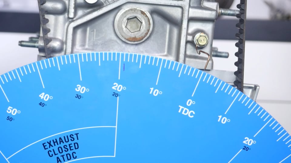
| 36:20 | Now we can have a look at our degree wheel. |
| 36:23 | So I'll just see what we've got here. |
| 36:25 | So remember we're looking at degrees before TDC. |
| 36:28 | We've got our TDC point over here and we are moving anticlockwise so in this case we're 10, 20, I'm gonna call that 24 degrees before TDC. |
| 36:40 | Now you'll see that I also have a purple mark here. |
| 36:45 | 23.5, one, two, three, 23.5 I'll call that. |
| 36:52 | I have a purple mark here for our actual desired opening point of 19 degrees. |
| 36:58 | So at the moment we are 4.5 degrees advanced. |
| 37:03 | In other words our intake valve is opening 4.5 degrees too early in the engine cycle. |
| 37:09 | OK so that's not enough though on its own, we also want to check our closing point. |
| 37:14 | So let's continue through and remember we know that our intake valve should be closing at 55 degrees after bottom dead centre. |
| 37:26 | So we can rotate through 'til we approximately get to that point. |
| 37:31 | And again I have made a purple mark on our degree wheel here. |
| 37:36 | So at his point we can see we're just moving past bottom dead centre. |
| 37:41 | And this time because we're moving past bottom dead centre, we want to take note of these black marks. |
| 37:46 | So you have 10, 20, 30, 40, and we're just coming up now on our closing point. |
| 37:57 | Hopefully you guys can see through there. |
| 37:59 | And again we are instead of 55, we're actually about 50.5 So what we've got from this is two pieces of information. |
| 38:11 | I'll just close this back down and come back to TDC. |
| 38:16 | So we wanted 55 degrees and we ended up with 50.5 So what this means is that both on the opening and the closing the valve, our valve timing events were 4.5 degrees too early. |
| 38:32 | So our camshaft is advanced in the engine cycle. |
| 38:35 | The intake valve is opening and closing too early relative to the crankshaft. |
| 38:41 | The other piece of information though that we've taken away from this is that our actual measured duration there at one millimetre of lift does match what the cam spec card gives us. |
| 38:53 | So this is our sanity check that we get by comparing two points there. |
| 38:57 | So if we had measured our intake valve opening point and found that we were 4.5 degrees advanced but we've then gone through and checked our valve closing point and found that for example we were bang on, this means that there is a discrepancy between the cam card's duration for the valve and our duration, in other words the duration that we've just measured would be 4.5 degrees too great. |
| 39:20 | So this suggests that something is wrong. |
| 39:22 | Either there is a problem with the cam grind, or much more likely there's been something that we've done incorrectly during our installation. |
| 39:29 | The obvious go to with our Honda B18C here would be that our valve lash has been incorrectly set because this will affect the relationship between the cam duration and the valve duration. |
| 39:44 | OK so in our example though we know that we were 4.5 degrees advanced. |
| 39:51 | So what we wanna do is make some adjustments to fix that. |
| 39:55 | And what we're going to do there is loosen off the lock nuts on our degree wheel and we're going to adjust the vernier cam gear not our degree wheel. |
| 40:08 | Before I do this, what I'll do is I'll just take over our remote camera and we'll have a look at those markings. |
| 40:15 | OK so what we're looking at is our little degree markings in here and you'll actually notice that for the purposes of our webinar, I have not actually had that dialled in on zero like I said we should. |
| 40:29 | And the reason for that is if I was on zero we'd actually have almost no work to do. |
| 40:34 | So what we wanna do now is we want to retard our cam by 4.5 degrees. |
| 40:41 | So we can use those little degree markings on our cam to help us with that work. |
| 40:47 | There is an important aspect to understand here that again is often overlooked though. |
| 40:53 | If we are going to be making adjustments there at our cam, we need to understand that because the cam rotates at half engine speed, that for each degree we move our cam at the cam wheel, that's going to affect our cam timing by two degrees. |
| 41:11 | So in other words to adjust our cam timing by 4.5 degrees, I'm going to end up moving the vernier cam gear by 2.25 marks or 2.25 degrees on the cam wheel. |
| 41:25 | Now we will be moving into questions and answers really shortly so if you do have any questions, please, this is the perfect time to ask those. |
| 41:33 | Now I'll just go through and we'll make that adjustment. |
| 41:38 | So our first step here is we have gone back to TDC. |
| 41:42 | And we are just going to loosen off the locking bolts here on our vernier cam gears. |
| 41:50 | Again as I said we want to make sure before we actually start that we have locked those up, just to make sure that the vernier cam gears aren't going to move in the process of dialling in our cams. |
| 42:03 | And now what I'm going to do is just retard that cam by two degrees or two markings. |
| 42:13 | And once we've got that retarded there, we'll just lock up our cam again. |
| 42:21 | Quite often while I am in the process of degreeing the cam, I'll end up just locking up one or maybe two of the locking bolts rather than all of them. |
| 42:33 | One of the key points, once you've gone through and you've completed the cam degreeing process though, all of those bolts do need to be correctly tightened and I generally recommend using a product such as, in this case I've got Loctite 243. |
| 42:49 | It's just a thread locking component, a thread locking product that's going to help prevent those working loose when the engine is operating. |
| 42:57 | OK so we've gone through and we've made an adjustment to our cam timing. |
| 43:02 | What we're going to do now is repeat the process and we'll have a look and we'll see how that has affected our actual cam timing, whether we're any close to our target. |
| 43:12 | So again I'm just going to rotate the engine around until we start getting our intake cam opening. |
| 43:20 | And hopefully this time we should be pretty close to the mark. |
| 43:25 | Right so come round and we've just got our intake cam opening now, coming up on half a mil of lift and we'll keep coming around, and that's one millimetre of lift. |
| 43:37 | Again just applying a little bit of pressure there. |
| 43:40 | So this point where you can see that we're pretty close, we're about 19.25 degrees there for our valve opening event. |
| 43:50 | So pretty close, for today's webinar I'm not gonna worry about making any further changes but let's continue through and we'll see how close we are to our intake valve closing event. |
| 44:02 | Just come back past bottom dead centre. |
| 44:09 | And we're just coming up on one millimetre now. |
| 44:19 | Again just being really smooth with that strong arm. |
| 44:22 | Right so we're on our zero point, that's one millimetre of lift. |
| 44:26 | And again we can see that we're about 54.25 degrees there so our purple mark there at 55 degrees. |
| 44:33 | So we're about a quarter of a degree off there but certainly not something I'm going to be worrying about for the purposes of this webinar. |
| 44:41 | Now one other point as well when we are going through this process, it is important to just make sure, if we look at our dial gauge here, we can see that our dial gauge is sitting on zero with the intake valve closed. |
| 44:55 | So it's really important to make sure that before we go through the process of measuring our valve opening and closing events, we need to zero the dial gauge with the intake valves closed. |
| 45:07 | And we need to go through a couple of full engine cycles there just to ensure that the dial gauge is in fact coming back to zero. |
| 45:14 | If it's not, this can affect the consistency of our results. |
| 45:18 | In this case, this is the process we've gone through there, we've got our adjustment made, we've only made one adjustment. |
| 45:26 | And by carefully measuring where our intake valves are opening and closing, and by carefully using the degree markings on our vernier adjustable cam gear, it is actually quite easy to correct any error that we've got in one change. |
| 45:41 | As we've just seen there. |
| 45:44 | Alright so again we will move into questions and answers so if you do have any more questions, please ask those and I will answer them. |
| 45:52 | I will just reiterate one more time though, once we've gone through, we're happy with everything, everything's degreed to the manufacturer's specifications, it is really important to make sure that we go through and lock up those vernier adjustable cam pulleys, just to make sure that nothing is going to move. |
| 46:10 | John has asked, how critical is the use of aftermarket cam gears with using aftermarket camshafts? Is it really necessary? Yeah in most instances it is. |
| 46:20 | It's really going to depend on how aggressive the cam profile is. |
| 46:26 | So again this really comes back to what I was talking about at the start. |
| 46:29 | A lot of people do use aftermarket cams with a factory cam gear. |
| 46:33 | But there's no guarantee whereabouts the camshaft centrelines are, where the valve opening and closing events are in relation to what the cam manufacturer has recommended. |
| 46:45 | Now there are a few cam manufacturers though that do design cams to be dropped into a stock motor with the stock cam gears, that's a different situation. |
| 46:57 | So definitely once we start getting into the more aggressive cam profiles, this becomes an essential aspect. |
| 47:04 | The other point here though is that we've just dialled in that intake cam to Kelford's inlet cam recommended valve opening and closing points. |
| 47:15 | Now that gives us a baseline to begin our tuning process from but this is only their recommended starting point. |
| 47:22 | It's quite possible that when we get onto the dyno, we may want to make some further adjustments to that cam timing. |
| 47:29 | And any time we advance or retard the cam, this is going to affect the efficiency of the engine in different areas of the rev range. |
| 47:37 | So we may still find on the dyno that some further changes are necessary to get the engine performance doing exactly what we want it to do, and of course that's not going to be possible if you have fixed cam gears. |
| 47:51 | Nick has asked will I be discussing cam phasing maps and reflashing software, it's a bit of a grey area for me. |
| 47:57 | Sorry Nick in this instance we are really dealing solely with the mechanical aspect of cams. |
| 48:04 | So we're talking here, it's more an engine building rather than an engine tuning webinar. |
| 48:09 | We do have a number of webinars in our archive available to our members that cover the aspects of adjusting the variable valve timing systems in bother factory and aftermarket ECUs. |
| 48:24 | John has asked, titanium or steel valve retainers with daily driving on a turbo charged four cylinder car? And what's the pros and cons? Not looking to go over the stock rev limit of the B18C. |
| 48:35 | I think there's probably in all honesty a lot of hype around titanium, obviously it is a fairly advanced material and it has a price tag that goes along with it accordingly. |
| 48:47 | Titanium does give the advantage of being stronger for the same amount of material so the upshot of this is that the retainer can end up being manufactured lighter than an equivalent steel retainer. |
| 49:04 | That's really going to become more of an advantage when you start really looking at very high rev limits. |
| 49:11 | That's when the mass of the valve train starts to become more and more important. |
| 49:16 | So for a stock rev limit for a B18C, there would be no strict advantage or no significant advantage I should say, in going from steel to titanium. |
| 49:29 | And in all honesty probably the weight saving would be minimal anyway. |
| 49:33 | There's no downsides in my own experience with reliability with titanium retainers. |
| 49:38 | I've run them successfully on street engines as well as drag engines and I've never had a titanium or a steel retainer fail for that matter. |
| 49:49 | Dallas has asked, what would cause the guide pin or dowel pin on a camshaft to shear off on a stage three Kelford cam on a Mitsubishi Evo 10 4B11? Stage three head with around 350 torque. |
| 50:03 | Four bent valves and nothing else is broken or worn. |
| 50:06 | Not 100% sure what would cause that. |
| 50:10 | There's probably a few potential culprits there. |
| 50:14 | One of them would be if the cam gear was not correctly tightened onto the cam, and this can allow the cam gear to actually work backwards and forwards or in other words fret and that could end up causing the dowel to fail. |
| 50:29 | When the cam gear is correctly torqued, that dowel is really not providing any, how would I put it, it's not providing location service when it's in action, it's just to locate the cam wheel initially when it is being tightened up onto the camshaft. |
| 50:50 | Once the cam wheel is correctly tightened onto the camshaft, that dowel should not be providing an alignment job so hence there's no force being applied through the dowel. |
| 51:00 | So that's my first guess, I'm not 100% sure what else could have caused that. |
| 51:06 | Vicarant has asked, what is the reference position for cam phaser for this engine with respect to TDC? I'm not 100% sure I've got your question there. |
| 51:22 | Yeah no I'm sorry if you maybe wanna elaborate on that question a little bit more and I'll try my best to answer that. |
| 51:28 | John's asked, how critical is the use of aftermarket cam gears, yeah OK we've already answered that one. |
| 51:33 | Next question is what's the best way to set TDC with pistons that either have a high dome or a deep dish. |
| 51:39 | Can this be done with a positive stop? Yeah absolutely so that's why both of the stops that we've looked at, the one that we can place across the deck, as well as the brass one which we used for our demonstration today are both adjustable. |
| 51:53 | So essentially regardless whether you have a dish piston or a high crown on your piston, you can still adjust the height of those stops to stop the piston when it's just a little bit down from TDC so yeah absolutely still possible. |
| 52:12 | Magic Mike has asked is there anything to be aware of when doing quad cam engines? Yeah I think a lot of people get scared off by quad cam engines and think it's a lot more work and realistically it's just exactly the same. |
| 52:24 | We're just treating the engine as two banks of cylinders. |
| 52:28 | So we'll go through the process of degreeing the cams on one bank of cylinders. |
| 52:33 | If you've got a quad cam engine you're going to have to do the intake and the exhaust cam. |
| 52:37 | And then we're just going to need to repeat the process on the other bank of cylinders. |
| 52:41 | What it does require us to do is relocate or find TDC on the front cylinder on the opposite banks. |
| 52:49 | So we will actually have to relocate our degree wheel so that we're on TDC on that other cylinder. |
| 52:55 | One thing that we do need to be aware of, obviously when we're degreeing our cams, we always want to be as accurate as possible but when we are looking at a V configuration engine or a horizontally opposed engine, we want to be very very certain that the cam timing bank to bank is as close to identical as possible, otherwise that's going to affect the volumetric efficiency from one bank to the other. |
| 53:24 | Motor Ray has asked, how important is that quarter of a degree? It would be a nightmare doing back and forth on quarter of a degree. |
| 53:30 | Honestly I just wouldn't worry about it. |
| 53:32 | If I'm within a quarter of a degree, I would be more than happy with that. |
| 53:36 | And you're absolutely right, particularly with a really small diameter cam gear like that, it's going to be really tricky to be much more accurate than that and you could end up going crazy going back and forwards making sure that you cam timing is absolutely perfect. |
| 53:52 | One of the reasons I say that I wouldn't be worried about being any more accurate than that, is that because we have access to our own dyno, I'm always going to be confirming the power curve on the dyno and probably almost inevitably I'm gonna be making some further adjustments to the cam timing to see if I can pick up or gain anything in the areas of the power curve or the engine's rev range that I'm interested in. |
| 54:17 | Once we get the engine in a car and get it on the dyno. |
| 54:22 | Cone has asked, do we need to degree drop in cams for engines that have variable cam timing? OK so with variable valve timing, engines know. |
| 54:32 | This is very different because the cam timing is adjustable on the fly and controlled by the ECU. |
| 54:40 | So these cams are very specifically manufactured to work with those variable cam pulleys. |
| 54:46 | And the phasing between the cam lobes and the locating dowel in the cam on that sort of a cam is much more precisely controlled. |
| 54:58 | Ultimately though then once the engine is on the dyno, it becomes the tuner's responsibility to optimise the cam control mapping inside the ECU. |
| 55:09 | Dereck Halsey has asked, without a cam card, how do you find the centreline on asymmetrical cams? Well without a cam card you're probably shooting blind anyway because what would you be degreeing the cam to? So really I mean if I'm dealing with an aftermarket cam by virtue of the fact I'm dealing with the cam manufacturer, I will be getting a cam card, I will be getting the information that I need in order to correctly degree the cam. |
| 55:37 | What we've talked about there with the asymmetrical grinds, obviously as I've discussed, you are going to end up inherently with an error. |
| 55:46 | The error is going to depend on the grind itself as well as how far down from peak lift you measure. |
| 55:53 | So if that's your only option, and I really can't see why it would be, you'd be wanting to be as close to peak lift as you possibly can get when you are finding the centreline that way. |
| 56:06 | But as I've said, that's not my recommendation on how we'd do it. |
| 56:10 | Drowsy has asked, how would you degree cams with VVT? So couple of questions that we've obviously had about this already. |
| 56:18 | So with VVT often if we've got an engine that has variable valve timing only on the intake cam, it is quite common that we would supplement that with a vernier cam gear on the exhaust cam. |
| 56:32 | What we find is that the engine's performance is much more sensitive to the intake valve timing than the exhaust timing, which is why we see a lot of the engines that are currently out there, have variable valve timing only applied on the intake valve. |
| 56:48 | So yeah we'd supplement that with a vernier cam gear on the exhaust cam exactly the same process that we've just looked at, we'll go into degreeing the exhaust cam. |
| 56:57 | But with the intake cam, because this is computer controlled, it comes down to the tuner's job of optimising that cam timing in operation. |
| 57:06 | Barry has asked, how do you account for motor with hydraulic lifters? Good question there Barry. |
| 57:11 | So this does present a little bit of a difficulty because in operation when we are degreeing the cams often those hydraulic lifters are going to bleed down, making it impossible for us to get really accurate repeatable results when we are checking our valve timing events. |
| 57:27 | So when we are degreeing an engine that uses hydraulic lifters, my technique there is to use a solid or adjustable check lifter just for the process of degreeing the cam. |
| 57:40 | So this does involve another step and a little bit more complexity. |
| 57:45 | Particularly with a hydraulic motor, when we are putting a solid lifter in for the purposes of degreeing our cam, we also need to adjust that check lifter, our adjustable lifter, we need to adjust that so that we have zero valve lash which is how a hydraulic cam operates normally. |
| 58:04 | So depending on the type of engine you're dealing with, this can be a bit of a pain in the ass to be quite honest. |
| 58:09 | And often there are aftermarket adjustable solid lifters that are available so using one of those, if you can get hold of one cheaply is a good way of getting through that process. |
| 58:22 | The other way you can go about making your own solid lifter for the purposes of setting your cam timing, by removing the check mechanism from a hydraulic lifter and fitting a solid shim in place. |
| 58:37 | Or alternatively the other way you can do this, if you've got a spare hydraulic lifter, is you can align everything, get the cam running on the base circle of the cam for the valve that you want to check, and then very carefully tig weld the hydraulic lifter in that position so it won't move. |
| 58:58 | So this is obviously gonna depend if you've got easy access around the lifter and can do that, and that'll get you through that process. |
| 59:06 | So yeah does include a little bit more work unfortunately. |
| 59:12 | John has asked, do you measure piston to valve clearance after degreeing the cams? Yes you do. |
| 59:18 | So this is gonna come down to how agressive your cams are. |
| 59:24 | So if you are doing a basic off the shelf cam for a common performance engine, like the cams we're dropping into our B18C, often the cam manufacturer is going to be able to tell you if you've got any likelihood at all of running into problems with valve to piston contact and quite often that just simply isn't going to be likely at all. |
| 59:48 | The bigger problem we have is when we're starting to really push the boundaries using really really aggressive cam profiles with large duration and high lift. |
| 59:56 | This is where we're likely to run into problems with valve to piston contact. |
| 59:59 | Again the cam manufacturer's likely to be able to give you some guidance as to whether or not it's going to be an issue. |
| 01:00:05 | Ultimately the responsibility still comes down to the person assembling the engine. |
| 01:00:08 | In our upcoming cam degreeing course, we actually have module on checking valve to piston contact. |
| 01:00:16 | But of course if you are going to check the valve to piston contact, it's something you do need to do with the cam degreed properly. |
| 01:00:24 | There's no point checking the valve to piston contact and finding out that maybe your cam timing was eight to 10 degreed out from where it needs to be, that's gonna obviously affect the valve to piston contact quite dramatically. |
| 01:00:38 | John has asked, when you say steel retainers are fine, are you referring to stock retainers, even with a stronger spring and revving higher? Unless there is a known problem with the retainers in your engine, that is probably the case. |
| 01:00:53 | However what you're going to find is that if you are looking at a significant increase in rev range, often you're going to end up using a double valve spring and that will come in a kit with a specific retainer made to locate the inner and outer springs correctly. |
| 01:01:09 | So when you get into that situation, you'll be using a full kit more often than not in my experience. |
| 01:01:17 | Ally Rose has asked, could you damage a motor if the cams are not degreed. |
| 01:01:21 | Yeah absolutely. |
| 01:01:23 | This sort of comes back to what I was just talking about with potential problems for valve to piston contact. |
| 01:01:28 | And again I mean this comes down to how big the cams are. |
| 01:01:32 | So for a small drop in cam like our Honda B18C cams here are mild I should say. |
| 01:01:38 | Our drop in cam probably less of an issue. |
| 01:01:41 | We could probably have got away with just dropping these in with the cam wheels both set to zero. |
| 01:01:46 | But the other aspect there is the performance deficit. |
| 01:01:49 | In particular with this set of cams, while the intake cam ended up being dialled in almost perfectly at the zero mark on our block's cam wheel, what we actually found is that the exhaust cam needed to be adjusted by about eight degrees of crankshaft rotation which is quite significant. |
| 01:02:08 | So if we'd dropped them both in on zero, wouldn't have ended up damaging the engine but we definitely wouldn't have got the performance that the manufacturer has suggested. |
| 01:02:19 | OK so we've got a follow on from the question that I didn't quite get earlier regarding the cam phaser for this engine. |
| 01:02:26 | So the question is the reference position of the intake and exhaust valve used by the ECU to determine volumetric efficiency and MBT. |
| 01:02:32 | OK I think I've got what you're meaning there. |
| 01:02:35 | So this is gonna depend from one engine to another. |
| 01:02:37 | In the case of our Honda, what we end up with is two sensors. |
| 01:02:42 | There is a sensor located in the distributor which is run off the end of the inlet cam. |
| 01:02:51 | So when we are adjusting the cam timing, this is common on a lot of engines, they either run a distributor off the cam or alternatively with a cam angle sensor. |
| 01:03:01 | What you need to do any time you're adjusting the cam timing is recheck and adjust your base ignition timing. |
| 01:03:09 | If you don't do this, often you're going to find that when you adjust your cam timing, you're also gonna end up offsetting your ignition timing. |
| 01:03:15 | This can potentially be dangerous. |
| 01:03:17 | Particularly if you end up advancing the ignition timing without being aware of it, you may run into problems with detonation. |
| 01:03:24 | But at a minimum when we are making cam timing adjustments on the dyno, we want to make sure that the only adjustment we're making initially is the cam timing. |
| 01:03:33 | So what I mean here is that if we're adjusting the cam timing and also by virtue of this at the same time the ignition timing's being adjusted. |
| 01:03:42 | The change of ignition timing could mask the effect of the cam timing change that we've just made. |
| 01:03:50 | Matt has asked, how critical is it to maintain the advertised lobe separation angle between the intake and exhaust cams when adjusting the cam timing on the dyno? None of it is critical. |
| 01:04:02 | Really what you've got here is just like the opening and closing recommendations, the lobe separation angle, or in other words the overlap period where both the inlet and exhaust valves are going to be open, does come down to some fine tuning and finding out exactly what suits the individual. |
| 01:04:21 | So it's again something that we will want to potentially check and adjust. |
| 01:04:26 | Obviously you can't adjust lobe separation angle if you're running a single cam push rod engine. |
| 01:04:32 | This is only something that we can adjust with a twin cam or quad cam engine where we can advance one cam with respect to the other. |
| 01:04:41 | Advance or retard one cam with respect to the other. |
| 01:04:44 | So as we bring the cams closer together and increase the overlap, what we're going to find in particular though is our idle quality will suffer. |
| 01:04:56 | We're going to end up producing less vacuum at idle and we're probably also going to need to increase our idle speed in order to maintain a good quality idle. |
| 01:05:06 | So again though you're probably going to find that your cam manufacturer's specifications are gonna be pretty close to ideal. |
| 01:05:15 | And if you find, regardless we were talking here about just advancing or retarding the cams or looking at the lobe separation angle. |
| 01:05:21 | You're going to find that if what you find to be ideal on the dyno after you've degreed the cams in the workshop, significantly varies from what the camshaft manufacturer has recommended, this would be something where you may start questioning whether you were actually accurate with your cam degreeing in the first place. |
| 01:05:41 | Normally you're gonna find that the optimal performance is delivered pretty close to the manufacturer's specifications. |
| 01:05:50 | Our last question comes from Orlando who's asked, do you have to check the cam degree every time after replacing the head gasket? No unless you're changing the thickness of the head gasket or the cylinder head or the block has been decked. |
| 01:06:05 | And even then it comes down to exactly how much material has been removed. |
| 01:06:09 | So if you're just replacing a head gasket with exactly the same item, nothing's been machined, then no there's no need to check those components. |
| 01:06:16 | What you find is that as the components get machined or you go to a thinner head gasket, this has the effect of retarding the cam timing. |
| 01:06:25 | So something that is overlooked though. |
| 01:06:30 | Alright guys that's brought us to the end of our questions. |
| 01:06:32 | No we've got one more that's just popped in there from Ardy who's asked, how does anti lag affect your cam timing and what would you have to adjust for that? I wouldn't be making an adjustment to my cam timing to suit anti lag. |
| 01:06:49 | The anti lag system sort of is really a separate entity and what we're going to want to do is make sure our cam timing is optimised for best engine performance and then once we've got our cam timing dialled in, then we can tune our anti lag to suit. |
| 01:07:08 | Obviously the anti lag can affect the engine performance during the overlap period. |
| 01:07:14 | What we're doing is retarding the ignition timing and creating a combustion event that's happening very late in the engine cycle out into the exhaust. |
| 01:07:23 | But really yeah I wouldn't make a cam timing change specifically to suit anti lag or vice versa. |
| 01:07:31 | Alright guys again that's brought us to the end of our questions, so some great questions in there. |
| 01:07:35 | Hopefully that's given you a little bit more insight into the process of degreeing the cams and a little bit more understanding on what those numbers on our camshaft specification cards mean. |
| 01:07:46 | As usual if you do have any questions after this webinar has aired, please ask them in the forum and I'll be happy to answer them there. |


