170 | How to Measure Bearing Clearances
Summary
The oil clearances for the crankshaft and connecting rod bearings are some of the most critical clearances inside your engine. In this webinar we’ll look at how to use a micrometer and a dial bore gauge to check these clearances.
| 00:00 | - It's Andre from the High Performance Academy. |
| 00:01 | Welcome to another webinar. |
| 00:03 | In this webinar we're going to be looking at how we can go about accurately measuring our bearing clearances when we're doing a dummy assembly on our engine. |
| 00:13 | Now the bearing clearances, in my opinion, probably are one of the most critical clearances inside the engine, yet surprisingly, particularly for novice engine builders, it's one of those things that is often assumed or taken for granted. |
| 00:26 | It's assumed that the clearances will be OK and so often I see or hear of novice engine builders simply fitting a new set of factory or aftermarket engine bearings to their block and expecting everything to be OK. |
| 00:40 | Now sometimes you'll get away with that and other times sadly you won't. |
| 00:45 | And if you don't get away with it, it can cause some very very expensive engine damage. |
| 00:50 | So we really wanna monitor this and make sure that the clearances inside our engine are exactly what we want. |
| 00:58 | When I'm talking about the bearing clearances here, what I'm talking about is the clearance between the outside diameter of our crankshaft journal, and this goes for our main journals as well as our connecting rod journals, and the inside diameter of the bearing journals. |
| 01:12 | So in this case for our demonstration today we're going to be looking at the big end oil clearance on our Subaru FA20 engine. |
| 01:19 | So we're looking at the difference between our inside diameter of our bearing journal here in our conrod, and the outside diameter of our crankshaft which I've got on the bench. |
| 01:29 | We'll get into that in a little bit more detail shortly. |
| 01:31 | Now if that clearance isn't right, if it's either too large or it's too tight in both instances we can get ourselves into problems and we can end up with reliability issues. |
| 01:43 | We need a very specific amount of clearance for our oil. |
| 01:47 | And this is where our oil film sits, and contrary to popular belief, I know a lot of people think that the bearing surface runs against the crankshaft journal and that's not the case. |
| 01:59 | We're relying on that oil film to take up the clearance between our bearing shell and our crankshaft journal and we should never ever have metal to metal contact between the two. |
| 02:10 | If we do get metal to metal contact, we're going to instantly result in a significant amount of damage to those components and our engine will not last particularly long. |
| 02:19 | Now we will be having some questions and answers at the end of the webinar so if you do have anything related to this topic that you'd like to know, or anything that I talk about today that you'd like me to go into in a bit more detail, please ask those in the comments and we'll deal with those at the end of the webinar. |
| 02:37 | OK so first of all, if we're going to check our bearing clearances, obviously we need some specification in order to define whether or not we're OK, whether our clearances are too tight or whether they're too loose and one of the common questions I get asked is where should we get these specifications from? And my answer there is we always want to have a copy of the engine's workshop manual with us while we're going through a disassembly and a reassembly process. |
| 03:07 | So this gives you a huge amount of information about your particular engine. |
| 03:11 | It's going to give you every single clearance, it's gonna show you what the clearances should be as well as the accepted maximums and minimums, so you're going to know that particularly if you're building an engine to factory specification you're gonna know straight away whether you're within the accepted minimum and maximum, whether you can proceed. |
| 03:29 | The other aspect a little outside of the scope of today's webinar, is these engine workshop manuals also give you a huge amount of information about the torque specs for various fasteners, the correct way of assembling timing chains or timing belts, and a huge amount of other relevant information specific to your particular engine. |
| 03:49 | And obviously the next question comes up, where do we get one of these workshop manuals from? These days thanks to the wonders of the internet, often this is pretty easy, particularly if you're dealing with an engine that is maybe a few years old and relatively popular in the aftermarket, you can almost guarantee that with a few minutes of time on Google, you're going to be able to locate a pretty good copy of that workshop manual. |
| 04:15 | Just so you can see what sort of information is going to be provided here, we'll just jump across to my laptop screen for a moment. |
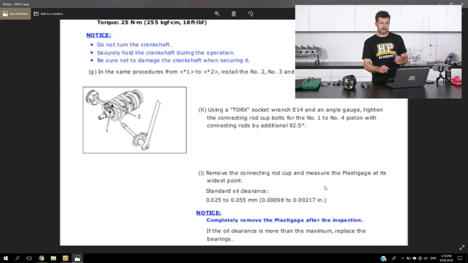
| 04:22 | And this is a page out of our Subaru FA20 engine relevant to our current task. |
| 04:30 | I'll just see if I can zoom in a little bit on this. |
| 04:33 | So we've got the process here for assembling the conrod onto the crankshaft in order to check our clearances. |
| 04:41 | Here they're talking about using plastigauge. |
| 04:43 | We're obviously not going to be using that today, we're gonna be using a micrometer and a dial bore gauge. |
| 04:48 | But it still gives you the process, and the important thing for our information here is the standard oil clearance is listed in both metric and imperial. |
| 04:59 | We're looking at 0.025 through to 0.055 millimetres or just under one thou through to just over two thou of clearance if you prefer to work in imperial. |
| 05:11 | So this sort of information is really really vital before we get too far into our engine building process. |
| 05:18 | Now I'll just see if I can, no it's not going to let me move, that's helpful. |
| 05:31 | Right the other aspect when we are looking at any of our specifications, is it is really important to make sure that our engine components are within spec before we start worrying about our clearance so actually I don't think I've got that page right here, but the process basically is to go through and make sure that all of our crankshaft journals measure up on size. |
| 05:55 | So just like the page that we've looked at there for our oil clearance, we're also going to have specifications for minimum and maximum diameters for all of the journals on our crankshaft. |
| 06:05 | So we can go through and make sure that those journals are within specification. |
| 06:09 | That's our first job. |
| 06:11 | If the journals aren't within specification then we may need to start by replacing the crankshaft. |
| 06:16 | So this would be a situation where there may have already been some wear on the crankshaft and this could end up influencing the overall diameter of the journal. |
| 06:26 | So obviously if there's wear on the journal and the journal diameter isn't where it should be, then we end up in a situation where we're unlikely to have the sort of oil clearance that we should be achieving and there's no point trying to put a band aid on the situation where the actual problem is our crankshaft there's no point putting a band aid on this by trying to use a different bearing shell in order to get our clearance where it should be. |
| 06:53 | So as a very rough rule of thumb here, we normally expect our bearing clearance our oil clearance, to be somewhere in the region of about one thou per inch of journal diameter. |
| 07:06 | So what I mean by this is if we've got a crankshaft with a two inch diameter journal, we should be expecting our oil clearance to be somewhere in the region of about two thousandths of an inch. |
| 07:16 | Now it is a rule of thumb so there's always exceptions to this rule, and our Subaru FA20 is a classic example. |
| 07:23 | While our big end clearance there for our connecting rod pretty much follows this rule, what we find is that the recommended clearance on our main bearing is actually significantly tighter. |
| 07:34 | The factory clearance there is listed at one thou through to 1.9 thou. |
| 07:40 | The reason this is tighter is because it is an alloy block so we set our clearance at room temperature a little bit tighter knowing full well that that alloy block is going to expand a little bit and our clearance is going to change when the engine is at operating temperature. |
| 07:56 | So still fundamentally important to start with your workshop manual. |
| 08:02 | The other aspect here is the workshop manual is perfect if you are building a factory specification engine or one that's at least relatively close to factory specification. |
| 08:14 | The factory specifications though are designed for factory power output and they're also designed for a factory rev limit. |
| 08:21 | So when we start really heavily modifying our engine, particularly if we're looking at maybe double or triple or quadruple the factory power and maybe extending our rev limit to one, maybe two, three thousand RPM beyond the factory rev limit, then everything changes here. |
| 08:37 | What we need to take into account is that as we put more stress into our engine components, we're going to get more flex from those components. |
| 08:46 | And if we run the factory clearances, this increases the chance that we can have metal to metal contact on those components. |
| 08:54 | As I've already mentioned, that's a recipe for just about instantaneous disaster or failure so we wanna stay away from that. |
| 09:01 | The general guide here is that if we're building a very high output engine, where we're increasing the power level and the RPM range or both of them, then it's typical that we, in the aftermarket would build a slighltly looser clearance than the factory specifications. |
| 09:19 | In this case we may want to add perhaps as much as half a thou of additional clearance to our big end and our main journals. |
| 09:27 | That just allows a little bit more room for movement before we get into that situation with metal to metal contact. |
| 09:33 | We'd also typically couple this with a heavier grade oil, a thicker viscosity oil so that we still achieve the oil pressure that we want, and by doing so we end up with a thicker film of oil that's going to potentially offer better protection to our engine components. |
| 09:51 | At this point it is also worth mentioning that the trend we see in professional level motorsport is actually completely the opposite. |
| 09:59 | In professional level motorsport we often see engine builders actually moving to tighter tolerances with very high output engines. |
| 10:07 | Now that gives them some advantages because that allows them to use a thinner viscosity oil, this reduces the frictional loses inside the engine and in turn can help to free up a small amount of power. |
| 10:19 | You do need to understand though that the companies working at this level have access to specially designed engine components in terms of bespoke engine blocks, specially made billet crankshafts, that generally are going to be significantly more rigid than what we get access to when we're dealing with OE specification parts. |
| 10:40 | So what works at that sort of budget level, probably isn't going to filter down and work too well for us at the more hobbyist level of motorsport. |
| 10:50 | OK so with all of that in mind, how can we measure our clearances if they are so important? One way we can do this for a novice engine builder, if you're not really confident, it's better to actually leave this to your engine machinist. |
| 11:04 | I am a firm believer that if you're going to be the final person touching that engine and putting it together, finally the onus rests on you to check and confirm that every single aspect of that engine build is exactly as it should be. |
| 11:18 | This is where we get into a bit of a grey area where often an engine machinist would do the machining work, supply the parts, something's maybe been overlooked, let's be honest, even a good engine machinist is still human, things can be overlooked, things can be missed, or things can go wrong. |
| 11:34 | But we should be picking this up during the final checking and the dummy assembly process. |
| 11:39 | So a lot of novice engine builders will leave the clearances and the clearance checking to their engine machinist. |
| 11:46 | Personally because I'm a bit fussy, I will always want to do this myself. |
| 11:49 | So our next step, and we've run a number of webinars on this, and there is a webinar in our archive for our members to view, this is also covered in our engine building courses, is the use of plastigauge. |
| 12:01 | Now I know that a lot of engine builders don't really believe that well in using plastigauge. |
| 12:08 | It's considered to be a cheap and inferior product that's not going to give you good results. |
| 12:13 | I personally believe that if you understand how to use plastigauge, you can get excellent results. |
| 12:18 | And particularly for a novice engine builder who's not maybe that confident using specialist measuring equipment such as micrometers and dial bore gauges, you're actually more likely to get a good result using a piece of plastigauge than you are with much more expensive much more specialised equipment. |
| 12:37 | However when you get to a point where you're really wanting to extend your knowledge and you're wanting to sort of invest a little bit more in your engine building knowledge, then obviously you want to step up and start using the micrometer and dial bore gauge, so that's what we're going to cover today. |
| 12:54 | So the two products we're going to use, micrometer we've got here. |
| 12:58 | Again, specialist piece of measuring equipment, I'm not going to cover how to use the micrometer in today's webinar. |
| 13:05 | Again we do cover this in another webinar in our archive. |
| 13:09 | So after this has aired, if you do want a little more information on how to correctly use a micrometer, I know they confuse a lot of novice mechanics and novice engine builders, check in our archive, just search for micrometer and you'll find that. |
| 13:22 | And to go along with our micrometer, we're going to be using a dial bore gauge. |
| 13:27 | So the principal of these two products and how we're going to use them, we're going to use our micrometer initially to measure the outside diameter of our crankshaft journal. |
| 13:37 | So here we're going to be looking at our big end journal. |
| 13:40 | There's two pieces of information we can take away here. |
| 13:44 | First of all we're going to take multiple measurements of our journal, and again referring this back to our workshop manual, we can confirm that the journal is on size it's within specification. |
| 13:56 | That's our very first step as I've mentioned. |
| 13:59 | Once we know that it's on size, we're going to use our micrometer, and we're going to use that to then zero our dial bore gauge, we'll go through that process in a second. |
| 14:09 | And once that's zeroed we can then place our dial bore gauge into our bearing journal on our connecting rod and we're going to end up seeing what the difference is, what the difference between the outside diameter of our crankshaft journal and the inside diameter of our bearing journal, that's going to be our oil clearance. |
| 14:29 | OK so let's just talk about this dial bore gauge a little bit. |
| 14:32 | They're nothing particularly fancy here. |
| 14:35 | Essentially we have a dial gauge on the end of a shaft here. |
| 14:40 | At the end we've got the head of the dial bore gauge. |
| 14:43 | This has a fixed anvil at one end of it and a moveable anvil at the other end. |
| 14:48 | And we'll just head across to our overhead shot now. |
| 14:51 | And what I'll do is just move the little moveable anvil in and out and we can see that as I do that it moves the dial gauge so that's what we're going to be looking at when we're reading it. |
| 15:04 | Now obviously with our dial bore gauge we're also going to be using it on a range of different diameters. |
| 15:09 | So again if we can just go to our overhead shot here, this is the kit that we've purchased, this is an Insize product. |
| 15:15 | And we can see that it works on anything from 50 mil diameter through to 105, or actually 160 millimetre in diameter if we use our extension. |
| 15:25 | So a pretty wide range there, we can use it for our bearing clearances. |
| 15:29 | As it's name implies it can also be used to check our bore size, we can check our bores for size, for taper, for out of round, and we can also check our piston to bore clearance. |
| 15:40 | The important thing which is often overlooked with a dial bore gauge is the dial bore gauge on its own is useless. |
| 15:46 | This is essentially you could consider a comparative tool. |
| 15:50 | So we need to actually zero the dial gauge first of all using our micrometer. |
| 15:56 | Alright so let's get into this. |
| 15:58 | What we're going to do is start by cleaning down the journal on our crankshaft that we're going to be measuring. |
| 16:06 | So here all I'm doing is using a clean rag and just a brake clean product. |
| 16:11 | So it's really important to make sure that you have properly cleaned down the journal surface so that you've got no oil, no dirt, no debris that can affect the reading that you're going to take with your micrometer. |
| 16:26 | Once we've done that, we can take our micrometer, just gonna back this off for a moment, and we're going to place our micrometer down over the journal, and we're just going to tighten that up. |
| 16:39 | And again if you do want more information on how to use the micrometer, please refer to our archive. |
| 16:47 | Once we've got a reading that we're happy with, just double check that, we can lock the micrometer off. |
| 16:54 | So our micrometer's now set, and what we're going to do is use that to zero our dial bore gauge. |
| 17:01 | So the process here is a little bit fiddly. |
| 17:04 | What I'll do is just move this crankshaft out of the way and we'll see if we can demonstrate this on our overhead shot here. |
| 17:12 | So what we're going to do is we're going to place the dial bore gauge in between the anvils of our micrometer and we're just going to swing this past, and yeah hopefully you should be able to see there, the pointer on our dial gauge and what I'm doing is just swinging it past the narrowest point. |
| 17:35 | So it's really important to move it around just gently so that we're really just seeing the narrowest point. |
| 17:41 | And we're seeing that we're coming right up on that zero point. |
| 17:44 | So obviously I've previously zeroed this, i just wanted to demonstrate the process. |
| 17:48 | So if we weren't zeroed there, all we need to do is loosen off our little lock for our dial gauge and we can rotate our dial gauge around until we're zeroed. |
| 17:57 | So it's really important to take the time to do that properly. |
| 18:00 | So at this point our dial gauge is ready to take a measurement. |
| 18:05 | Before we do that though, what we wanna do is now install our bearing shells into our connecting rod. |
| 18:10 | So again it's really important here to make sure that all of the components we're using are clean. |
| 18:16 | So for our demonstration here we've got a set of Brian Crower H beam rods for our Subaru FA20 and we've also got a set of ACL race series bearings. |
| 18:28 | So again just using a brake clean or isopropyl alcohol will also work, what I'm going to do is take all of these components and just make sure that there's no oil, no dirt, no debris on any of the products, any of the components. |
| 18:41 | Likewise we can do exactly the same for our bearing shells. |
| 18:46 | It's really really easy to end up affecting the accuracy of our reading if we've got any oil or contaminants on these surfaces. |
| 18:55 | So once we've got everything cleaned down we can assemble our bearings into our conrods. |
| 19:01 | So I'll just do that here on our overhead camera. |
| 19:04 | So what we wanna do is just assemble the bearing shell initially into the cap here with the locating tang just in the little cut out in the conrod. |
| 19:14 | And now a common mistake I see a lot of people make when they're installing bearing shells is from this point what they'll do is just push the bearing shell down, and all that does is it scrapes the backing off the shell against the sharp edge of our connecting rod cap. |
| 19:29 | So what we wanna do is actually use our thumbs to apply a little bit of pressure inwards towards the centre. |
| 19:35 | Essentially we're crushing down the bearing shell slightly as we push it forwards with our two thumbs. |
| 19:41 | And what that's going to do is make sure that we locate the bearing shell into the connecting rod without scraping anything off the back of the bearing shell. |
| 19:49 | So we're going to repeat that process here for our connecting rod body. |
| 19:53 | And once we've done that, I'll just use my one thumb there to do that, once we've done that we can then assemble the cap and the body together and we would then torque that to specification required. |
| 20:07 | So in this case we're using an ARP 2000 rod bolt which calls for 45 foot pound of torque if we're using a torque method in order to tighten that. |
| 20:17 | So I've already got one which I have previously torqued down. |
| 20:20 | So what you want to do now is we want to take our dial bore gauge, and again I'll just do this on the overhead shot. |
| 20:27 | I'll just move our crankshaft out of shot a little bit. |
| 20:34 | So what we want to do is take our dial bore gauge and place this in the connecting rod journal and just gently place that in the journal there, and we're looking to just move this backwards and forwards. |
| 20:52 | And we're looking for the minimum reading that we've got there. |
| 20:55 | So we can see that we're coming down to just a touch over 4000ths of an inch. |
| 21:00 | Sorry actually I should've mentioned, just to add to a little bit of confusion today, we are using a metric dial gauge. |
| 21:08 | So this is actually 0.04 or 400ths of a millimetre. |
| 21:13 | We're just a touch over 400, sort of maybe 4.5 hundredths of a millimetre. |
| 21:18 | So it's important just to rock it backwards and forwards and we're just looking for the point, the minimum point. |
| 21:24 | So that's the technique we're going to use there and of course we then want to compare that back to our specification in our workshop manual. |
| 21:34 | So let's just head back to that now. |
| 21:39 | Head across to my laptop screen. |
| 21:40 | So remember in metric units here we were looking for 0.025 through to 0.055 millimetres so we've got 0.04, maybe 0.0425 of a millimetre clearance. |
| 21:55 | So we're well within that range there, and for those of you who prefer to work in imperial units, we can convert that, again I'll just do this on our overhead camera. |
| 22:08 | So we had 0.04 and we wanna divide that by 25.4 so we see that that's approximately 1.6 thousandths of an inch. |
| 22:17 | So regardless whether you are working in imperial or metric units, it is really really easy to swap between those units if you simply remember that there are 25.4 millimetres in one inch. |
| 22:33 | OK so that's the process we go through, and regardless whether we are going to be using our dial bore gauge and micrometer for our big end of our connecting rod, or for the main bearing journal in the engine block itself, the process is exactly the same. |
| 22:49 | It can get a little bit tricky though, particularly on maybe an inline six cylinder engine to get right through to the centre main journal using a dial bore gauge so we can get longer dial bore gauges, which will be suitable for that particular application. |
| 23:05 | An alternative though is we can, if we have individual bearing caps, we can do one cap at a time to give us access to the bearing journal that we're interested in looking at. |
| 23:18 | So once we've gone through and we've confirmed all our measurements, we know whether our clearances are where they need to be. |
| 23:25 | Now we're going to move into some questions pretty soon, so if you do have anything, again, that I've talked about here, please ask them, anything that you'd like to know more about, please ask them in the comments or anything generally related to this particular topic. |
| 23:41 | OK so the next question we often get is what do we do when we find that our clearances aren't where they should be? And obviously that's a situation we are going to find ourselves in from time to time. |
| 23:54 | And this can be a little bit tricky, but there are a few solutions. |
| 23:57 | So generally particularly a lot of the more modern performance orientated engines, you're going to find in the workshop manual that when it comes to selecting bearings for a particular journal, that there are, what is referred to as graded bearings. |
| 24:14 | So what we can do here is we can look at the match marks on the engine block for the particular journal we're interested in, or alternatively the connecting rod, as well as marks or numbering that we'll have on the crankshaft. |
| 24:28 | And by matching those up on a grid, this will give us the factory specification for the bearings shells we should be putting on that journal. |
| 24:35 | So obviously if everything is in as new condition, there's no wear on the components, this should give us the factory oil clearance specification very accurately. |
| 24:45 | So in a way this is basically like factory blueprinting. |
| 24:48 | Now we can of course influence this in our own favour by using different bearing shells, using that grading system from the OE manufacturer to make small adjustments to our oil clearances and get them where we want them to be. |
| 25:02 | In some instances in the aftermarket, we can purchase bearing shells that will give us additional clearance. |
| 25:09 | Some manufacturers produce shells that give an additional thousandth of an inch clearance for example. |
| 25:17 | And that may be enough just to increase the clearance to where we may want it to be. |
| 25:23 | The hardest situation though is if our oil clearance is already excessive. |
| 25:27 | In this case the only real option we have is to grind the journal on the crankshaft undersize and then we couple this with an undersize bearing shell to take up that additional space. |
| 25:40 | So basically this gives us a free rein to adjust the journal size to actually get the oil clearance that we want. |
| 25:48 | And often if we're trying to shoot for something that is not factory, in terms of our oil clearance, the technique that we would go through here is to assemble the component, be it the connecting rod or our engine block, with our undersize bearing shell. |
| 26:01 | Measure the journal diameter that we have in there and then use that with our oil clearance in mind, in order to grind our crankshaft to the correct finished size. |
| 26:12 | So there is a little bit of flexibility in there, but of course it is always a bit of a frustration when we go through and measure our components and find that the clearances aren't what we wanted. |
| 26:21 | It is however always better to know this in advance than find our the hard way when we go to actually run our engine and we end up with metal to metal contact or insufficient oil pressure, and then we have to pull our engine apart and go through the whole process again. |
| 26:37 | Alright we'll go through and have a look at some questions now. |
| 26:42 | Ale has asked, what do you think about Prolong lubricant? Not something that I've personally used myself sorry. |
| 26:49 | I've got no opinion that I can offer you on that one. |
| 26:54 | Andy has asked, do you throw away the rod bolts if they are a one time use type? Generally in the aftermarket, I'm always dealing with some kind of connecting rod that has an aftermarket rod bolt. |
| 27:09 | So I actually surprisingly couldn't tell you the last time I rebuilt an engine that used factory rod bolts or for that matter just about any factory fasteners. |
| 27:19 | So a typical performance engine build is almost always going to use a set of aftermarket rods, unless there's a really good reason not to. |
| 27:27 | Those are gonna come, typically the most common would be an ARP rod bolt. |
| 27:32 | Likewise we're also going to typically be fitting a head stud kit and a main stud kit so you do need to be careful with, this is more to do often with head bolts and main bolts. |
| 27:45 | Often factory engines use what's referred to as a torque to yield fastener, which is a one time use fastener. |
| 27:52 | So with that sort of fastener, what we're doing is tightening the fastener, or stretching it beyond its yield point. |
| 27:58 | So when we undo that fastener, it is permanently deformed, and we can't reuse that sort of fastener. |
| 28:04 | With the ARP or a lot of the aftermarket fasteners that we use in the performance industry, these are torqued down below their yield point which means that they aren't permanently deformed and this means that when we undo the fastener, it returns to its original length so we can reuse it. |
| 28:22 | With rod bolts it is, because these are the most stressed fastener that we've got in our engine, it is a good idea to keep a log of the lengths of the bolts and if we do find over subsequent tear downs that the bolts have stretched, then we do want to replace them. |
| 28:41 | The ultimate way is, well just getting a little bit off topic but I'll continue, the ultimate way of tightening our conrod bolts is with a rod stretch gauge instead of using a torque wrench, so we can actually directly measure the stretch in the bolt. |
| 28:58 | Craig has asked, is there a noticeable difference in measurement when the temperature changes 10 degrees or 30 degrees? Look I haven't taken exactly the same engine and measured it across a range of ambient temperatures. |
| 29:13 | Over a 10 degree change in temperature, I don't think you're going to notice a significant change. |
| 29:20 | It's also gonna come down to the component the material that you're measuring. |
| 29:24 | So I mentioned earlier in the webinar about the tighter clearance that we run on an aluminium FA20 block because that block will expand as it comes up to operating temperature. |
| 29:36 | So what I'm getting at here is the thermal expansion coefficient of aluminium is higher than steel. |
| 29:41 | So that's something to keep in mind. |
| 29:43 | Generally within reason, it's not that critical for us. |
| 29:47 | The reason I say that is we're generally going to find that in most instances, our workshop temperature's probably not going to vary over a range of much more than about 20 degrees so the net effect of that's probably going to be not too significant. |
| 30:02 | The other aspect is you hopefully remember back to the factory specification for our bearing clearance, it's actually quite wide, it's quite a significant range that the factory still deem to be acceptable. |
| 30:15 | So a variation of 10 or 15 degrees centigrade is probably unlikely to make a significant difference there. |
| 30:24 | Yeoh has asked, is there a general rule of thumb for choosing the desired viscosity of engine oil when engine load operating range and bearing clearances were increased in order to still maintain the minimum film thickness and bearing characteristic? OK so this is a really complex topic and I'll be the first to put my hand up and say I am not an oil specialist. |
| 30:46 | I know what I've tested myself through my own career building a number of very heavily modified drag engines, where we took the factory power level and multiplied that by about four, as well as taking an engine that in stock form revved to 7000, or 7500 RPM, and took that out to 10500, or 11000 RPM. |
| 31:07 | And I know the development we went through there. |
| 31:10 | So generally what I like to do is use slightly looser clearances, as I alluded to earlier. |
| 31:16 | With our 4G63 drag program, we were adding around about half a thou clearance to both the big end and the main journals over the factory spec. |
| 31:25 | And we ended up in that particular engine, running quite a heavy grade oil. |
| 31:29 | We ran a 15W50 full synthetic oil. |
| 31:33 | This oil provided the sort of protection that we needed on the bearing shells in the journal, and it also gave us the oil pressure that we needed. |
| 31:42 | So there are a number of considerations there and particularly if you are running a factory oil pump, one of them will be your oil pressure. |
| 31:50 | So all things being equal, if we rebuild an engine with looser clearances, and we run the factory viscosity oil, you're going to find that your oil pressure will drop. |
| 32:00 | Simply there's more area for that oil to leak out internally inside the engine, so hence your oil pressure will drop. |
| 32:06 | So you're almost definitely going to need to jump up your oil viscosity. |
| 32:10 | With our modern engines though, this comes to be a little bit more complex because we're seeing most of our performance engines these days use continuously variable cam control, and that relies on oil pressure through the cam wheel in order to advance or retard the camshaft. |
| 32:27 | So you'll see that the majority of late model performance engines normally specify a relatively thin oil, maybe something like a 0W20 or a 5W30. |
| 32:37 | And by moving to a very thick oil, maybe a 20W40, 15W50 et cetera, the thicker oil can impair the ability of that cam control system to function as quickly and track target as quickly as it potentially should. |
| 32:54 | So that's something you need to kind of weigh up. |
| 32:57 | And generally, in a long winded answer to your question there Yeoh, it would be a case of simply testing and finding out what works, what gives you the sort of oil pressure that you want, and if you've got a cam control engine, still giving you sufficiently fast control of the cam timing and cam position. |
| 33:18 | Barry G has asked, what are your views on mixing bearing sizes per journal to achieve the correct clearance? Are there any dos and donts when using this approach? It's not actually something that I've personally done outside of using factory graded bearings. |
| 33:33 | It does sound like a shady practice, but in essence it isn't. |
| 33:38 | So one of the things to consider here, which a lot of people again overlook, is that our bearing shells actually provide what's referred to as eccentricity. |
| 33:48 | So the journal itself here isn't completely round the whole way. |
| 33:51 | And if we used our dial bore gauge to check the clearances across the parting face of the cap there, we're actually going to find that the bearing clearance there is significantly larger than if we look at it in the direction that the bearing's going to be loaded. |
| 34:06 | So in that case there is no real problem with using different shell thicknesses. |
| 34:12 | Obviously within reason, we're talking very small differences here, generally, if you are going to be mixing and matching across graded bearing shells. |
| 34:22 | Generally in the performance engines that we're involved with, if we do want to make adjustments to the oil clearance, what we're going to do is actually have the crankshaft polished or even ground to achieve that clearance, and use a suitable set of shells. |
| 34:38 | One of the reasons for this is not because I'm adverse to, or opposed to using mixed shells like you've mentioned, but one problem we do see is if the engine ends up going elsewhere, gets torn down and gets rebuilt, often another engine builder won't be quite as fussy and maybe notice what has been put in the engine, so it's likely that we're going to end up with a set of matched shells and the clearances may then no longer be correct. |
| 35:10 | Jamie has asked, would you say it's worth switching to an ACL or King bearing from an OE bearing, even if the clearance is within tolerance. |
| 35:17 | I.E. do the aftermarket bearing benefits really succeed the OE bearing? That's a really good question Jamie. |
| 35:23 | I've used both factory bearings and the variants of race series bearings in our own race engines and I've had good results with both, however what you do need to understand is why these race bearings or high performance bearings are in existence. |
| 35:39 | And generally if we look at the construction of an OE bearing, what we have is quite a thick upper layer which is referred to as an imbedability layer. |
| 35:48 | So no matter how good your cleanliness is, no matter how well your filtration system's working for your oil, you are going to end up with some amount of debris being pumped through the oil. |
| 35:59 | And that imbedability layer on the top surface of the bearing shell is there to trap that debris, these very fine pieces of debris. |
| 36:08 | They get trapped in that top layer of the bearing shell so they don't end up damaging the crankshaft journal. |
| 36:13 | The downside with that design is while it's great for long term reliability of our engine, we don't end up damaging our crankshaft, what we end up with is inferior load handling capability. |
| 36:25 | So essentially you could think of the bearing as being a little bit easier to deform. |
| 36:30 | That top layer is a little bit softer and easier to deform. |
| 36:33 | So with the race series bearings, that imbedability layer is much much thinner and this provides a much stronger bearing, it's able to support more load without deforming. |
| 36:44 | And the downside of course is we don't have that level of imbedability so they generally are more suited to very high output engines that are going to see regular tear downs. |
| 36:56 | This is because simply the bearing shells may not actually last as long because they don't have that imbedability. |
| 37:02 | Hopefully that explains things. |
| 37:04 | One other aspect as well, I know this is an aspect that ACL sort of advertise with their race series bearings, is the improved heat transfer out of the bearing shell back into the engine component, either the conrod or the engine block. |
| 37:23 | So there's a lot of heat being produced in that journal and we wanna get rid of that heat. |
| 37:29 | So the conformity of the back of the bearing shell to the engine component that it's being fitted to is superior and it improves the heat transfer. |
| 37:37 | So there's a couple of aspects to consider there. |
| 37:42 | Yeoh has asked, do you compensate for the deviation of diameters of each journal by pairing it with bearings of different diameter? OK I think we've sort of covered that question previously with the answer to Barry's question. |
| 37:53 | David has asked, you mention the only solution to excessive oil clearance is to regrind the journal and go to undersized bearing. |
| 38:00 | Are there circumstances where you could use an oversize bearing, one designed to fit rods that have been honed out as a way to close the clearance down? No, OK so you're right there, we've got the ability to purchase from various manufacturers, both oversize and undersize bearing shells. |
| 38:18 | The oversize bearing shells are designed with a larger outside diameter. |
| 38:23 | So as you've mentioned there, this would be something that we could fit into a connecting rod, where maybe the tunnel size has been increased or in the engine block, wherever you're fitting those components. |
| 38:36 | The problem with this is we need a certain amount of crush with our bearing shells once everything is torqued in place. |
| 38:43 | So once the bearing cap is actually torqued down, what we're doing is we're crushing the bearing shell, and that's what actually holds that bearing shell in place and stops it rotating. |
| 38:53 | A lot of people incorrectly think it's the locating tangs on our bearing shells that prevent the bearing shell from spinning in the journal. |
| 39:01 | That's not the case, it is the crush. |
| 39:02 | So that's essential, that's an aspect of the journal diameter and the bearing shell outside diameter. |
| 39:11 | So if you end up doing what you referred to there, you're gonna end up with excessive crush and it's just not going to work. |
| 39:18 | Hopefully that explains things there. |
| 39:21 | Joey has asked, should the journals be measured in multiple areas, 90 degrees from one measurement? Yeah absolutely so this really comes back to the first step which we haven't really covered here. |
| 39:33 | I mentioned that one of the first steps is we're gonna go through our crankshaft, we're going to measure each of the journals and we're going to measure in multiple points to make sure that it is within specification. |
| 39:43 | So what we're checking here is that it is within specification, but by measuring at multiple points, particularly two points perpendicular to each other, this is going to allow us to confirm that the journal is nice and round. |
| 39:58 | So you'll also find in the factory manual, there is a specification for the maximum allowable out of roundness on a journal so this is what we're going to go through here. |
| 40:07 | We also measure at each edge of the journal as well as in the centre and this allows us to check the journal for taper as well. |
| 40:15 | Andy's asked, if checking the clearance, when you may reuse the existing bearings, does the clearance change from the original? I'm not quite sure I follow your question there Andy. |
| 40:31 | So if you're reusing the existing bearing, does the clearance change? From the original specification? I'm not sure there what you're sort of referring to. |
| 40:41 | Regardless whether you're reusing an existing factory bearing or existing bearing, if you are gonna be doing that, you'll still wanna check your clearance and make sure it's OK. |
| 40:51 | In this case though, basically unless there was some wear on the crankshaft journal, you would expect that that clearance should be exactly where it was when the engine was last built. |
| 41:01 | Spooner's asked, Spoon Honda's asked, we're building a Honda K20A2 with a Darton sleeve, hoping to push it past 1000 horsepower. |
| 41:09 | Is it necessary to line bore the main bearings on that engine after sleeving it? The answer is it may or may not be. |
| 41:17 | You need to check. |
| 41:18 | What you will find is that with the installation of those MID sleeves, there's a huge amount of machining gets done to that K20 block. |
| 41:28 | And it's a hugely time consuming process and it also produces a lot of heat. |
| 41:33 | You're actually removing quite a lot of the structural integrity of the block as designed by Honda. |
| 41:39 | Obviously with the intention of improving it clearly for your particular purposes. |
| 41:44 | So it is quite possible because of where the sleeves sit that this could cause some distortion to the main bearing tunnel. |
| 41:55 | Personally I'd be more worried about the distortion in that main bearing tunnel that's likely to come from you fitting a set of heavy duty main studs which I'm certain that you'll probably also going to be doing. |
| 42:07 | When you do that in an alloy block, because that alloy block is relatively soft, the improved or increased clamping force that comes from the aftermarket stud kit, is almost certainly, in my experience, going to produce some form of distortion in that main bearing tunnel. |
| 42:24 | So lined boring is probably not going to be necessary. |
| 42:28 | There's two processes there that can be used dependent on the amount of material that needs to be removed and how much that journal needs to be tidied up. |
| 42:37 | So line boring is pretty severe, this would be used for example if you are fitting a set of billet main caps and there was a lot of material that needed to be removed out of the main caps. |
| 42:47 | For your purposes we would probably use a process called line honing. |
| 42:51 | And this is a finishing process, if you've had the engine line bored, it's used after line honing and this gives you a finish size on the journals and also ensures that everything has the right surface finish on it. |
| 43:06 | 2004 LS1 RX8 has asked, are there certain bearing materials that should be used for very high spinning motors? Example a D stroke V8 with a capable 11K RPM limit. |
| 43:19 | So this really comes back to the question we were talking about earlier with these race series bearings versus an OE bearing and the improved load handling capability of those bearing shells. |
| 43:31 | So this goes for both engine RPM and engine power. |
| 43:36 | So certainly at a very high RPM rev limit, then yes I would probably be veering towards one of the performance bearing brands. |
| 43:47 | Something designed for performance use, you're probably going to get better reliability out of that bearing. |
| 43:54 | If you want a little bit more information about that as well, if you check out on our YouTube channel, there is an interview with King Bearings at PRI and that covers the difference between an OE bearing and their performance series bearing so you'll have a better understanding of that. |
| 44:11 | Probably easier than me trying to explain it in detail here. |
| 44:15 | Tony has asked, if you crush a bearing in a conrod for checking clearance, can you use them again for final assembly? Yeah absolutely there's nothing wrong with that. |
| 44:21 | As I mentioned before, there is a small amount of crush on those bearings to keep them in the journal. |
| 44:27 | But they're not deformed or damaged, they are reusable, so yep not a problem at all. |
| 44:34 | Barry has asked, do you have any experience with the coated bearings, e.g. King's racing bearings? If so have you seen any benefits from those coatings? To date I have not had any experience with coated bearings at all. |
| 44:47 | The LS1 that we're abut to put together, we will be using a set of coated bearings so hopefully I'll have a little bit more input on that in the not too distant future. |
| 44:58 | Now one thing to keep in mind, again, a lot of people sort of get confused with the coatings, thinking that it's going to give better abrasion resistance to the journal. |
| 45:09 | Again, just to reiterate, it's really important to remember that the journal should never be touching the bearing shell. |
| 45:15 | If it does, no coating's really going to give you much of a buffer in terms of long term reliability, you're gonna have some pretty serious problems on your hands. |
| 45:25 | Alright guys that brings us to the end of our questions, some really good questions in there so hopefully this webinar has been useful to everyone and hopefully everyone's learned something. |
| 45:34 | As usual if you do have any more questions please ask them in the forum and I'll be happy to answer them there. |
| 45:41 | Thanks guys. |


