172 | Measuring Piston To Bore Clearance The Correct Way
Summary
One of the most critical measurements in your engine is the clearance between the piston skirt and the cylinder wall. In this webinar we’ll look at how to use a micrometer and a dial bore gauge to find this clearance.
| 00:00 | - Hey guys it's Andrew from High Performance Academy, welcome along to this webinar where we're going to be talking about our piston to cylinder wall or piston to bore clearance. |
| 00:09 | We'll find out what exactly that specification or clearance is, and why it's so critical. |
| 00:15 | And then we're going to have a look at how we can go about measuring this using our Subaru FA20 block that I've got here on our workbench. |
| 00:22 | As usual with all of our webinars, we will be having a question and answer session at the end of the webinar, so if there's anything that I cover today in the webinar that you'd like me to explain in more detail, please ask those in the comments and we'll get to those at the end of the webinar. |
| 00:38 | So we'll start with the simple question of what exactly is the piston to bore clearance? And really its' pretty well explained in the name. |
| 00:46 | We're simply looking at the clearance that we have between the outside diameter of our piston skirt, and the inside diameter of our bore in our engine block. |
| 00:58 | Now it's essential that we have the correct amount of clearance there. |
| 01:01 | If our clearance is too tight, what's going to happen is that as the piston expands with heat, during operation, the piston is going to expand out, the skirt's going to contact the cylinder wall, and in a worse case scenario it can end up seizing in the bore So obviously no future in that, definitely not something we want to occur. |
| 01:23 | The flipside of that is if our piston to bore clearance is excessive, what we're going to end up with is in operation the piston is not going to be well supported and it's going to end up rocking backwards and forwards in the bore. |
| 01:36 | Now there's a few problems when this occurs. |
| 01:38 | First of all it's going to create a lot of noise which isn't exactly what we want. |
| 01:43 | Probably a lot of you will have already heard an aftermarket engine built with forged pistons that's maybe a little bit tired, and often during a cold startup, before the piston has expanded to normal operating size, this does create a lot of knocking from the piston rattling in the bore. |
| 02:05 | So that's what we get there. |
| 02:06 | The downside of this as well, other than the noise is that we're going to end up with excessive wear on the piston and potentially the bore. |
| 02:15 | We're also going to end up with the rings not being held as stably in the bore so this actually can affect our ring seal and in turn can effect the performance of the engine. |
| 02:27 | So obviously detrimental there, we don't want that happening. |
| 02:30 | And the last aspect there which really goes hand in hand with getting our rings stable in the bore, is that if we're running excessive piston to bore clearance we can end up finding that we're going to be using a lot more oil. |
| 02:43 | So all of those things we obviously want to stay away from. |
| 02:46 | So getting our piston to bore clearance on specification where it should be is really really critical. |
| 02:53 | So next we'll talk about what tools we're going to need in order to do this job. |
| 02:58 | So this is one of those jobs where if you want to be checking this sort of clearance yourself at home, you are going to need to shell out a little bit of cash on some precision measuring equipment. |
| 03:11 | So the first piece of equipment you're going to need is a micrometer, or more likely you're going to need a set of micrometers. |
| 03:18 | What we find with our micrometers is that they only work across a certain range. |
| 03:23 | So for example this is a three to four inch micrometer so it is only able to measure sizes between three and four inches. |
| 03:34 | So obviously if we're going to be measuring a range of different piston sizes or for that matter, if we're gonna be using our micrometer set to measure a range of different components, we are going to need more than one micrometer. |
| 03:45 | When it comes to micrometers you also do need to decide, whether you're going to be purchasing a micrometer set that is metric or imperial. |
| 03:55 | For those of you who have followed a few of our engine building webinars or taken our engine building course, you'll know that despite coming from New Zealand where we do use the metric system, I am a big advocate of being able to work in both metric and imperial units. |
| 04:12 | The reason for this is that we're going to be sourcing a lot of our components, in this case we're going to be using a JE forged piston sourced from the United States for our webinar. |
| 04:21 | So a lot of the components are going to be coming out of the US, and this means inevitably they're going to be delivered with imperial specifications. |
| 04:30 | So even if you do work predominantly in metric, it really is important to be able to work in both metric and imperial units and convert between the two. |
| 04:39 | Really easy though if we just remember that there are 25.4 millimetres in one inch. |
| 04:45 | And just to be really confusing for today's webinar, I'm going to be working in both units because we have an imperial micrometer yet the second piece of equipment that we need to do this measurement is a bore gauge and to confuse matters a little bit, we are going to be using a metric bore gauge. |
| 05:05 | So doesn't really matter here, again as long as we understand what we're using, we don't get confused between imperial and metric units, and we know how to convert between the two of them. |
| 05:15 | So the bore gauge, as its name implies, can be used to measure our bore diameter, can also be used as we see to measure our piston to bore clearance. |
| 05:24 | These also can be used to measure our bearing clearances, so it's a pretty important tool to have around if you want to start measuring your own clearances. |
| 05:34 | Now it is important to mention here that a lot of home enthusiast engine builders will rely on their engine machinist to do all of this work for them. |
| 05:45 | So while I certainly recommend it, this isn't something that you necessarily need to be doing yourself, and I just wanna talk about that a little bit. |
| 05:54 | For me personally, I believe that the onus is on the person doing the final assembly of the engine to make sure everything is correct. |
| 06:04 | So what I mean here is if we're working in conjunction with an engine machinist to perform all of the heavy lifting, machining our engine components such as doing our boring and honing, maybe polishing or grinding our crankshafts et cetera, then a lot of engine builders will just assume that that engine machinist has done their job properly, and then blindly clean and assemble the engine without checking any of the work. |
| 06:28 | For me I believe that really the person doing the assembly needs to check and be really confident that everything is correct. |
| 06:34 | The reason for this is we do need to understand that machinists are still human and even a really high end good quality machine shop can still make mistakes. |
| 06:45 | Now while no one wants to have a mistake on their engine components, it's always much easier to pick this up during the dummy assembly engine building process, rather than get to a point where your engine is fully assembled and find the hard way where the engine actually fails, that something wasn't quite right inside the engine. |
| 07:03 | This also gets into the kind of complex and fuzzy area of if that does happen, then who's fault is it? Personally I think you're probably better to just bypass those awkward conversations and just check everything and make sure that it is right the first time around. |
| 07:17 | OK now the other thing I'll mention here is that if your engine block has been torque plate bored and honed by your engine machinist, then you are also going to need the torque plate when you go through and measure your piston to bore clearance. |
| 07:32 | Now again I'm going to just cheat a little bit and confuse matters here. |
| 07:35 | As we can clearly see, our FA20 Subaru engine block doesn't have a torque plate fitted to it at the moment. |
| 07:42 | We actually have had this block torque plate honed. |
| 07:44 | The reason I don't have the torque plate fitted is because it just makes it a little bit more complicated and difficult for us to demonstrate the actual process here. |
| 07:53 | So under normal conditions, if I was actually building this engine, we certainly would be using a torque plate during the measurement process. |
| 08:02 | OK so we know what tools we need, now we'll talk about how much piston to cylinder wall clearance we actually need. |
| 08:13 | And this is a bit of a tricky one, because it is going to depend on primarily the piston as well as the piston or bore diameter. |
| 08:22 | So the material the piston's made out of is a big driving factor in what our bore diameter should be. |
| 08:29 | As well as the way the engine's going to be used. |
| 08:31 | And really what it all comes down to here is the amount of heat that's being produced inside the combustion chamber, and then being transferred down through the crown of the piston, which finally obviously heats up the entire piston as well as the skirt, and makes the whole piston expand out. |
| 08:46 | So what we're trying to do when we are checking, setting our piston to bore clearance here at room temperature in the workshop, is to set a clearance that's going to give us the actual desired clearance we need in operation when everything is stinking hot up to operating temperature. |
| 09:04 | So for a factory cast piston, generally we're going to be able to run very very tight piston to cylinder wall clearances. |
| 09:13 | These may be down in the range of about 1000th of an inch, sometimes a little bit more, sometimes a little bit less. |
| 09:19 | And this is great for OE manufacturers, this is just one of the reasons why cast pistons are favoured in an OE application. |
| 09:26 | Because the cast pistons don't expand very much with heat, they can run that very tight piston to wall clearance. |
| 09:33 | This reduces noise, we don't get that rattling or rocking of the piston in the bores when the engine's cold. |
| 09:40 | It also makes sure that the piston is nice and stable as is the ring pack on the piston in operation, this reduces wear and it reduces oil consumption. |
| 09:49 | So obviously all great things. |
| 09:51 | Of course the problem with this is that cast pistons can be a little bit brittle and a little bit weak so they're not always suited to high performance applications. |
| 10:02 | This is why often we will end up moving to a forged piston such as the ones we've got here. |
| 10:08 | Now there are a couple of alloys that are used in the manufacture of forged pistons. |
| 10:13 | By far and away the most common for very high performance forged pistons is 2618. |
| 10:20 | Now this is a low silicon content aluminium and the upshot of this is that when compared to a factory cast piston, a 2618 forging will expand more as it heats up. |
| 10:36 | Naturally what this means for us is that when we are fitting a set of forged pistons, particularly if it's a 2618 alloy, we need to provide more piston to cylinder wall clearance. |
| 10:47 | So we need more piston to cylinder wall clearance when the engine is at room temperature, so that when everything heats up and expands under operating conditions, we have the ideal amount of piston to cylinder wall clearance. |
| 11:00 | So I've mentioned that for a stock cast aluminium piston, we may be somewhere in the region of 1000th of an inch. |
| 11:08 | For a forged 2168 piston we're quite likely to be somewhere in the region of four to five thou, or even greater depending on a range of different factors that come into play there. |
| 11:21 | OK so we know about our clearance, now we also need to understand, when we go about checking our piston to cylinder wall clearance, we need to understand where abouts on our piston skirt we are measuring. |
| 11:33 | So this is one of the areas that is often confused by novice engine builders. |
| 11:40 | When we look at our piston like this, it's really easy to assume that the piston skirt is parallel from the top of the crown to the bottom of the skirt. |
| 11:48 | Where in fact it's actually not. |
| 11:50 | Most piston skirts are machined with a barrel profile. |
| 11:54 | So what this means is that if we check the diameter of the piston from the top of the crown to the base of the skirt, what we'd actually find is that the profile changes. |
| 12:04 | So we find that somewhere down near the base of the skirt is the widest point on the skirt and this is where we want to make that measurement. |
| 12:12 | So if we're making the measurement in the wrong place on the skirt, we're going to end up with completely wrong information. |
| 12:20 | So fortunately when we purchase a set of pistons, we're going to get some information about the piston, and we'll just use our remote camera here and I'll show you the relevant information here. |
| 12:31 | This is for our Subaru piston that we're going to be using. |
| 12:35 | And we can see here that the gauge point as it's called, is in this case seven millimetres up from the base of the skirt. |
| 12:42 | So that's really important information that we want to take into account, before we go and make that measurement. |
| 12:48 | Now I'll just also move up a little bit further on this information. |
| 12:53 | Because when it comes to choosing our piston to bore clearance, we're not left on our own. |
| 12:57 | And in this case we can see that JE recommend, for this particular set of pistons, that we use 0.004 of an inch, or 4000ths of an inch. |
| 13:05 | Or if you wanna work in metric, 0.1016 millimetres. |
| 13:09 | So that's the sort of information that we're going to need from the piston manufacturer in order to decide what our clearance should be. |
| 13:18 | This information also needs to be given to our engine machinist during the engine machining process so that they can achieve the correct piston to bore clearance. |
| 13:28 | It is also worth mentioning here that these are some rough guidelines that JE give out. |
| 13:34 | So this will be suitable for probably 75% to 90% of people using these forged pistons in most applications. |
| 13:42 | If you are using these pistons in some relatively extreme circumstances though, then you may need to adjust that clearance to suit. |
| 13:53 | So remembering here that we're setting our piston to bore clearance, based on the amount of heat being produced as well as the usage of the engine. |
| 14:03 | This is really what we want to take into account when we're deciding on our piston to bore clearance. |
| 14:08 | So for example here, if we were designing this engine to run extremely high boost pressure, on a pump gasoline for example, and it was also intended to run for long periods of time under high load, what we know that this is going to do is produce a lot more heat in the combustion chamber, and that heat in turn is gonna be transferred into the crown of the piston and into the skirt of the piston. |
| 14:32 | So it's likely we could expect the piston to expand more, than if we were using exactly the same piston in a much lower powered road car application where it's simply not going to get such a hard time. |
| 14:43 | Should hopefully be pretty clear that under those extreme circumstances, we may need to provide a little bit of additional clearance. |
| 14:52 | Likewise if we're running on perhaps an alcohol fuel, maybe we're running a lower boost pressure producing less power, alcohol fuels tend to run a little bit cooler, we may be able to get away with slightly less clearance. |
| 15:05 | And another aspect with our clearance as well, if you are building up the same engine repeatedly, this gives you the opportunity to tear down an engine after it has been used, and inspect how the pistons have been wearing. |
| 15:21 | And by looking at the wear patterns on the skirt of the piston, this can give you a pretty good indication if your piston to cylinder wall clearance is correct or excessive or maybe even too tight. |
| 15:34 | In particular what we're looking for is signs of wear on the skirt of the piston, and where abouts that piston skirt has been contacting. |
| 15:43 | In general for a piston to cylinder wall clearance, that's pretty much on point. |
| 15:48 | What we're looking for is a slight wear mark, you're always going to see some amount of wear on the skirt of the piston, and it will be centralised on the skirt of the piston. |
| 15:59 | So if we're seeing something like this, this generally means that we have our piston cylinder wall clearance just about right. |
| 16:06 | OK we're going to go through a practical demonstration now of going through and making these measurements, and after this we will move into some questions and answers, so again if you do have any questions and answers, please ask them in the comments. |
| 16:21 | Alright so we'll go through the steps that are required here, and I'll demonstrate them on our Subaru FA20. |
| 16:27 | So obviously the first step here is to check the specifications from our piston manufacturer so that we know what we're looking for. |
| 16:35 | In this case as we've already seen, we're looking for 0.004 of an inch, 4000th of an inch, which happens to be 0.1016 millimetres. |
| 16:44 | Remembering for our demonstration today, we are using a metric bore gauge. |
| 16:50 | So the metric measurement 0.1016 millimetres is what we're going to be using for that. |
| 16:56 | OK so the other aspect here is that when we take our pistons out of our packaging, we also want to inspect the pistons and just make sure that they haven't been damaged or bruised in transport. |
| 17:08 | So particularly we're looking at the skirt of the piston just to make sure that there's no obvious marking. |
| 17:14 | Likewise it's also a good idea to just inspect the ring lands of the piston as well as the crown just to make sure that nothing's contacted that piston. |
| 17:23 | It's also really easy if a piston has been dropped off a bench and you're not aware that that's happened, then obviously it's very easy to distort the piston and damage it. |
| 17:33 | Now once we've got our piston and we're confident that it's all in good condition, we want to note that gauge point that we've already looked at. |
| 17:41 | So you remember that we were looking for a point seven millimetres up from the base of the skirt. |
| 17:47 | Now personally I find it's a really good idea to actually mark that gauge point on our piston skirt. |
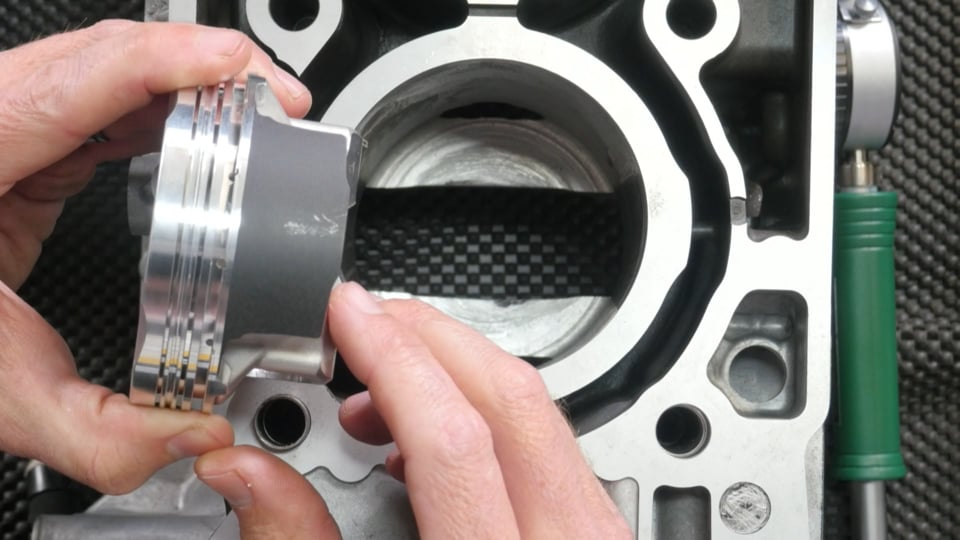
| 17:54 | So all we can do here is just take, in this case I'm using a set of vernier callipers, and we just want to measure up from the base of the skirt there. |
| 18:02 | And we'll just go to our overhead camera and hopefully you'll be able to see. |
| 18:06 | I've actually put a little black sharpie marker mark on that skirt, both sides, just so I've got a reference point of where I can align my micrometer. |
| 18:21 | So with that out of the way, we know where we're measuring our piston and we can take our micrometer. |
| 18:26 | Again we do have a webinar on how to use a micrometer so if you're not familiar with how to use the micrometer I would suggest that you go and check that out as well so you really understand what we're going through here. |
| 18:42 | And what we want to do is hold our micrometer, and we're just going to locate that micrometer over the match marks that we've just made. |
| 18:52 | Now this is a delicate process here because what we want to do is gently move our micrometer around and make sure that we are getting the widest part of that piston skirt. |
| 19:03 | So not only do we need to make sure that our micrometer is correctly aligned in this plane here, we also need to understand that, let's go to our overhead camera here. |
| 19:16 | If we're looking at our piston skirt, we want to be measuring the widest point here so if we move our micrometer across to one side of the piston skirt, obviously that's going to affect our measurement. |
| 19:28 | So we need to be really careful that we do that. |
| 19:30 | Just a word about micrometers as well, this is something that's been brought up a couple of times, I'm not particularly critical about it, but do understand that by transferring heat from your hand into the frame of the micrometer, this can have an effect on the micrometer reading. |
| 19:50 | So we actually see that we do have a little plastic point to hold the micrometer. |
| 19:57 | And this is just helpful to reduce that heat transfer into the micrometer. |
| 20:00 | I just raise that just to be completely accurate in our discussion on using the micrometer. |
| 20:06 | So anyway we'll go back and we'll measure our skirt there. |
| 20:09 | And I'm just using the little thimble at the end of the micrometer just to avoid overtightening, and this just allows us to get a consistency, particularly if multiple operators are using the same micrometer, by using the thimble at the end of the micrometer, the ratchet thimble, this ensures that we do get consistent readings. |
| 20:28 | So once we've got our reading we can lock off our micrometer. |
| 20:31 | Now it is also a good idea at this time to compare the reading on our micrometer with what we've actually got on our specifications for the piston. |
| 20:43 | So in this case the bore diameter, the requested bore diameter, so this is what the machinist would be aiming for, is 3.405 of an inch. |
| 20:54 | Now remembering that our piston to cylinder wall clearance is four thou so obviously this means that our piston skirt diameter should be measuring 3.401 of an inch. |
| 21:06 | So it's just a good idea to as a bit of a sanity check, confirm that that is in fact the case. |
| 21:11 | If you're not measuring 3.401 inch, the correct skirt diameter there, then you'd definitely want to investigate why, either you've got a damaged piston, you've incorrectly measured that skirt diameter or there's a problem with your micrometer. |
| 21:26 | So that's our first sanity check there. |
| 21:28 | Once we've got our micrometer locked off at our measurement, we then need to set up our bore gauge. |
| 21:36 | So our bore gauge simply has a dial gauge at the top which we can zero. |
| 21:40 | A lot of people don't understand how a bore gauge works. |
| 21:44 | The bore gauge on its own is not that useful. |
| 21:48 | It is a comparative tool, so we need to zero our dial bore gauge, in this case in our micrometer. |
| 21:54 | So basically what we're doing is zeroing the dial bore gauge on the outside diameter of our piston skirt. |
| 22:00 | And then the dial gauge will give us the difference between that measurement and whatever we're inserting it into, obviously in this case, our bore diameter. |
| 22:09 | So the dial bore gauge is also designed for multiple diameter measurements. |
| 22:16 | So let's just place that down carefully for a moment and what we'll do is we'll jump to our overhead camera, and this is the kit of parts that comes with this particular dial bore gauge. |
| 22:28 | And we can see we've got a range of different little extensions that can be placed in our dial bore gauge, depending on what we're trying to measure. |
| 22:36 | So in this case anywhere from 50 mil up to 160 mil we can measure. |
| 22:43 | OK so once we've got our dial bore gauge set up there, we, sorry I'll just get rid of that. |
| 22:52 | Once we've got our dial bore gauge set up, we've got an extension there that's going to give us just a correct amount of preload in our bores there. |
| 23:01 | We want to make sure that when we actually place the dial bore gauge in our bores, that we are actually going to be able to see the dial indicator moving. |
| 23:12 | So once we've done that, we've got everything set up, the next step which gets a little bit fiddly is that we need to place our dial bore gauge inside, between the two anvils of our micrometer, and we need to zero our dial bore gauge. |
| 23:28 | And because this step is a little bit fiddly, I've already done this previously. |
| 23:32 | But the process is basically to insert the dial bore gauge between the two measurement points on our micrometer, and we want to rock that backwards and forwards across those two points, and we're looking for the smallest point, so it does take a few goes to get that right. |
| 23:51 | And what we want to then do is adjust the dial indicator so that we are zeroed on that particular measurement. |
| 24:00 | So let's just see if we can, let's go to our overhead camera now. |
| 24:04 | And we'll see as I'm just moving this backwards and forwards through the anvil there, we can see that we come right up to that zero point there. |
| 24:11 | So as I said I've already zeroed our dial bore gauge at this particular point. |
| 24:17 | So that sets our dial bore gauge on our zero point. |
| 24:20 | We also want to lock off the adjustment on our dial bore gauge so that nothing's going to move. |
| 24:25 | Then what we can do is place our dial bore gauge into our bores, just gently. |
| 24:31 | We want to then rock it backwards and forwards, we'll just get this across so you guys will be able to see it at home. |
| 24:38 | And what we're looking for here, remember we've got our zero point up here, and in this case each single interval on our dial indicator is 0.01 of a millimetre. |
| 24:50 | So we can see there that we're just coming up our smallest point there, as we rock through we see it comes smaller and then it'll start getting bigger again. |
| 24:59 | We can see that we are 10 increments to the left of our zero mark. |
| 25:04 | So in this case that indicates 0.10 millimetres. |
| 25:09 | So we can see that in this case we are right on our target of 0.10 millimetres. |
| 25:16 | Now the other thing that's important to do with our dial bore gauge though is to make multiple measurements. |
| 25:23 | So what we could do here, we've just looked at one point in our bore. |
| 25:26 | Now by dropping the dial bore gauge halfway down the bore and repeating the process, and then also at the bottom, what this is allowing us to do, is to see if we've got any taper, or any belling in the bores. |
| 25:41 | Likewise we can also take measurements perpendicular to each other. |
| 25:45 | So what I mean there is once we've taken one set of measurements, we would take the bore gauge out turn it 90 degrees and repeat the process. |
| 25:52 | And this allows us to ensure that our bores are true, they're nice and round. |
| 25:58 | We'll find as well that in our factory engine specifications, we will have a recommendation for any maximum taper or belling, and any maximum out of round. |
| 26:10 | Obviously in the perfect world we would want everything to be absolutely perfect, absolutely true, no out of round measurable and also no taper or belling. |
| 26:20 | But we will often see some small amount of inconsistency there, that in some instances is unavoidable. |
| 26:28 | Now again just repeating back to what I talked about with our torque plate here, there's not a lot of point, if we have torque plate bored and honed our engine block, there's not a lot of point making these measurements because the distortion that the torque plate induces, obviously that's supposed to replicate the cylinder head distortion when that's bolted to the block, will effect the bore shape when the engine is bored and honed. |
| 26:56 | So when we release that torque plate and take it off, it is quite likely, particularly in an engine block that is known to distort significantly, it's quite likely that when we check the bores with the torque plate removed, that we will find that bores aren't perfectly round. |
| 27:10 | So that's just something that you need to consider. |
| 27:13 | Alright so that brings us to the end of our webinar. |
| 27:17 | We'll just come down now and we'll have a look at our questions. |
| 27:24 | Flying Haggis has asked, the specs said to allow 40 thou clearance, but you said in high load applications we'd allow a little bit more. |
| 27:32 | So first of all four thou, not 40 thou. |
| 27:35 | If we had 40 thou we'd probably have a lot of trouble getting our engine started in the first place, but yeah four thou was the specification on that. |
| 27:44 | If we were building something for a very very high power application then we may want to allow an additional half a thou to one thou. |
| 27:55 | For an 86 millimetre bore which we're running here, if we end up much over about 4.5 to five thou, we're definitely going to have an engine that is quite rattly, particularly when cold. |
| 28:09 | And the other aspect with this is while we know that we're not going to have problems with our pistons seizing up in the bore, from the tuner's perspective this actually makes it a little bit trickier to tune the engine because an engine that's built with very loose tolerances or clearances like this, tends to be mechanically a lot noisier when we've got it on the dyno. |
| 28:29 | So particularly when it comes to aspects such as listening for knock, it can be really really tricky for us to really distinguish knock, over and above general mechanical noise. |
| 28:40 | Alright that looks like it's the only question we've got there. |
| 28:44 | As usual if you do have any further questions, please ask them in the forum and I'll be happy to answer them there. |
| 28:51 | Thanks for everyone joining us today and I hope you enjoyed the webinar, look forward to seeing you all next time. |
| 28:58 | Now for those of you who are watching on Facebook today, this is just a little bit of insight into what we put on every week for our HPA gold members. |
| 29:08 | Now gold members are able to review and rewatch these webinars in our archive, where we've currently got over 170 hours of webinar content. |
| 29:16 | We vary our topics between both engine building and engine tuning. |
| 29:20 | Now our gold members also get access to our private members only forum which is the perfect place to get fast and reliable answers to your specific engine building and engine tuning questions. |
| 29:30 | Gold membership is available on its own for USD$19 a month. |
| 29:35 | But any of our courses will give you three free months access to our online community. |
| 29:41 | So if you want to check that out, you can head to our website to learn more. |
| 29:45 | Alright thanks guys for joining us, and I look forward to seeing you online again soon, cheers. |