189 | How to Splice
Summary
Splicing a single wire out to multiple wires is something that must be done multiple times for every harness build, and there are always questions about the best way to go about it. In this webinar we'll look at how we size the splice to use, the required tooling, where the splice should be located in the harness, and perform a practical demonstration of the process.
| 00:00 | - Hi guys, Zac from the High Performance Academy here, welcome along to today's member's webinar where we're going to be talking about splicing. |
| 00:08 | So that's taking one wire and making a really nice reliable connection to one or more other wires. |
| 00:16 | This is a job you're gonna have to perform multiple times when you're building a wiring harness. |
| 00:21 | The example that always springs to mind for me is taking a single sensor ground wire and splicing that out to all the wires that head off to the multiple sensors in your engine bay. |
| 00:32 | There's of course other examples, a sensor supply is going to be a similar one to that and actually power supply circuits get spliced out a lot as well. |
| 00:40 | You're probably going to have a single, or couple of wires coming off your enable stage relay, they might head down to your ignition coils where it'll have to splice out to all the individual coils, and of course heading off to your injectors for the same purpose. |
| 00:53 | Not to mention exactly the same thing out of your main stage relay as well. |
| 00:58 | So no matter what you're building a harness for or what the project is, you are going to have to be performing multiple splices along the way. |
| 01:08 | So today we're gonna have a pretty in depth look at how I like to perform splices and a way I know that is really really reliable. |
| 01:15 | We're going to look at it in quite a bit of detail and get into a little bit of the math behind sizing the splice and talking about how we determine the amount of copper that we're actually gonna have in that splice to make sure we're gonna get a really reliable join. |
| 01:30 | So the first thing I want to talk about for splicing is where we're actually going to try and locate those splices in our wiring harness. |
| 01:39 | Now splices, if there is going to be a point of failure in your wiring harness, which of course we're trying to avoid at all costs, but if it is going to happen, splices are a pretty common culprit. |
| 01:52 | Now when I say common, failures in wiring harnesses built to a good level are pretty uncommon, but if they do happen, splices are one of the first places I start looking for them. |
| 02:02 | To try and mitigate some of that, when I'm deciding where to put a splice in a harness, I'm always going to choose to put that right behind a connector or at a harness transition point. |
| 02:14 | So by transition point I mean a section where the harness is possibly going from a larger trunk and branching out to the multiple smaller sections that might head off to the individual sensors and actuators in the engine bay. |
| 02:24 | Now the reason I like to place my splices there is that that way I can document very easily where they are in the harness so if I do find a problem with that particular circuit, I know where to go looking for it. |
| 02:37 | The other reason is that by putting the splices in that location, we're most likely going to be putting a strain relief boot in that same location which we can locate the splices underneath. |
| 02:51 | That is definitely a key part to making sure all your splices are nice and reliable in your wiring harness, getting them beneath those strain relief boots to make sure that they can't be getting tugged on in any odd directions which can cause them to fail prematurely. |
| 03:07 | Another benefit is that by locating your spices in those points, you never have a situation where halfway along a continuous section of harness, the size of the harness mysteriously increases because a single wire has spliced out to multiple wires. |
| 03:22 | You do want to avoid that if you can as it does tend to look a little bit unsightly in the harness and it can give you a bit of a tight spot if you've gotta get that harness through a grommet or say a piece of sheathing onto the harness when you're building it as well. |
| 03:38 | So hopefully that gives you a really good idea as to where you should be locating your splices and that fact that you should definitely not be just winging it on that decision, it is something you want to work into your design stage and document where you've located those splices as well. |
| 03:55 | Next thing we're gonna talk about are the actual type of splice that we're going to use and how we're going to size that splice. |
| 04:03 | So if I'm building a wiring harness for a club level loom, so I like to divide the wiring harness projects up into two sort of categories, we've got our level or modified street car harness and then we've got our professional level motorsport wiring harnesses. |
| 04:21 | Now the club level motorsport wiring harness, as soon as people hear that we've divided it up into two sections, they think that's going to be a budget low quality harness. |
| 04:30 | Absolutely not the case, we're still using really good materials that we have specified to be completely accurate for the situation and they are going to be nice and reliable, however we do have to factor budget into that decision as well. |
| 04:46 | So for that reason when I'm building a club level harness I like to use brass open barrel splices. |
| 04:51 | So I've got one here as a bit of an example. |
| 04:53 | I'll just hold it in my pliers and we'll pop over to, just use this bit of wire as a pointer here, pop over to our macro shot and have a quick look at it. |
| 05:02 | And you can see how they've constructed. |
| 05:05 | So they're made out of brass and that is actually quite important in this situation. |
| 05:09 | So in case you're not aware, brass is a alloy of copper and zinc. |
| 05:15 | And the brass used for these open barrel splices is around about 65% copper and 35% zinc. |
| 05:22 | That actually means that they're really quite stiff. |
| 05:25 | And we'll get into a reason that that's quite important in a minute when we talk about the tooling. |
| 05:33 | Another reason that it's very important is that when we're actually going to crimp this splice with our wires, with our copper conductor strands through the splice there, because it's brass and we're going to crimp it down and it's quite stiff, it's actually going to retain its shape through the life of the harness and keep pressure on those wires, keeping everything really nice and tight together there. |
| 05:54 | So the way these work is that we're going to strip back a section of the insulation from our wire. |
| 05:59 | The length of which is going to be determined by the size of the open barrel splice that we're using. |
| 06:06 | So you can see if I pop this through here, we'd be stripping off the insulation back here to give us enough copper conductor strands poking through there that we can see them on both sides of that open barrel splice. |
| 06:18 | And then we're going to insert the assembly into a tool that is going to fold these upper tangs over and it's going to grip everything really nice and tightly, and it's actually going to put enough pressure, because we have our tool calibrated properly, on this splice join, to essentially cold weld the copper conductor strands together. |
| 06:36 | They're going to be squished together so hard that they're basically going to become one piece of copper but only through the centre section of that splice there. |
| 06:46 | Just gonna have a quick look at my notes here for a second to make sure I haven't missed anything in that explanation. |
| 06:52 | I know the question that we're going to get asked an awful lot is where to source these splices. |
| 06:58 | We've got a couple of documents up available on our forum in the wiring fundamentals section up the top there that have actually got the part numbers of three open barrel splices that I use most often and where you can source those. |
| 07:12 | But for reference, the smaller one is a TE 62759, the middle size is a 63130, and the largest size is a 62357. |
| 07:26 | So if you google those numbers you will find the exact same TE open barrel brass splices that I like to use. |
| 07:33 | When we get into sizing our splice, which we're actually going to do right now because it's a really good time to put it in there, we'll talk about something called CMA which is circular mill area, now this is a little bit of an unusual measurement but it is a common one you find when you're dealing with wire sizes. |
| 07:54 | It's a very american measurement, in that it is based on inches, it's not a metric unit at all. |
| 08:01 | And it's a way of sizing an area, sizing a circular area, basically you're sizing a circular area as if it was a square. |
| 08:12 | The way you calculate the circular mill area of your wire is to look at the diameter of that wire and simply square it. |
| 08:21 | So if you think about how that works, that would actually give you the cross sectional area of a square that had the same distance between sides as the diameter of the wire. |
| 08:31 | So basically it's a way of avoiding having to include pi in the equation. |
| 08:36 | And because all these calculations end up referencing back to one another and we've got the splices are sized for that measurement, it does actually end up working quite well. |
| 08:48 | So the way you're going to calculate the circular mill area of your wire, is you're actually going to end up needing a little bit more detail about the wire you're using than you might otherwise think would be necessary. |
| 09:02 | So when I'm building a club level harness I'm most likely going to be using TXL wire and I use a lot of 22 gauge TXL wire when building a harness like that as it's a really good size for most injector power wiring and I almost exclusively use it for sensors. |
| 09:20 | The reason for that is that it's robust enough that it can withstand being handled by someone when the harness is being installed into the vehicle, and there's enough copper conductor strand in a 22 gauge wire that you can get a good reliable crimp join onto it when you're crimping a terminal onto it. |
| 09:37 | A lot of terminals are sized for 20 to 22 gauge wire. |
| 09:42 | Now the TXL wire I use for a club level harness typically is, well it's always a stranded wire, but typically it's made up of seven 30 gauge strands. |
| 09:54 | So when it comes to calculating the circular mill area of this wire, what we're actually going to do is calculate the circular mill area of a 30 gauge strand and then we're gonna multiply that by seven. |
| 10:05 | Now there is a formula for calculating that circular mill area, it's actually a formula for calculating the diameter of a particular AWG of wire. |
| 10:15 | I'm not going to go through that right now but what I will do is, I've actually made a post in our webinar section of the forum where I'll post that formula up. |
| 10:27 | But essentially it's 0.005 times 92 to the power of 36 minus the wire gauge you're dealing with, divided by 34. |
| 10:40 | So you can see why I'm not gonna go into that in detail now because everybody would absolutely fall asleep. |
| 10:45 | But what you're going to find is it's not too tricky when you've got a calculator in front of you to calculate the diameter of a single strand of the stranded wire that you're dealing with. |
| 10:57 | What you then do is square that number and that's going to give you the circular mill area. |
| 11:04 | Because as we talked about, circular mill area is basically a way of being lazy and not including pie in the calculation but it does work quite well because it's all referenced back and it's the information we have when we're sizing those splices. |
| 11:17 | What we find for our TXL 7/30 wires, so that's seven strands of 30 gauge wire inside there, is we end up with a circular mill area of almost exactly 700. |
| 11:29 | That's pretty typical for a stranded 22 gauge wire. |
| 11:34 | However when you get to the motorsport, professional motorsport level of harness construction, you're going to be using most likely Tefzel insulated wire, or Mil Spec wire as it's commonly known, and that is almost exclusively going to be a construction of 19 strands of, I think it's 34 gauge wire, yeah 19 strands of 34 gauge wire. |
| 11:57 | And if you go through the calculation process for that, what you're going to find is it has a circular mill area of around about 760, so you've actually got a wee bit more copper in that wire which can be a really good thing when you need just a little bit of extra capacity to flow a wee bit more current along that wire. |
| 12:14 | But it doesn't actually increase the size of the wire much because we've got that thinner insulation with that Tefzel wall. |
| 12:21 | But when you get into a situation where you might be splicing say a single 16 gauge power wire out to, could be as many as say eight injector power supply wires, that extra 60 of CMA per individual wire can actually bump you up a size in the splice that you're going to need to use. |
| 12:39 | So while you can look up some reliable and useful charts online, that have CMA values for some common wire types. |
| 12:47 | That little bit of background knowledge is probably pretty important to have as well to make sure that you are using the right calculations for the situation that you're in. |
| 12:58 | However talking about our club level harness again, where we're using our open barrel brass splice, the demonstration I'm going to show here, because we'll show a practical demonstration of actually performing an open barrel splice join, so you know what you have to be aware of there. |
| 13:12 | The demonstration we're going to go through is taking a single wire here and splicing that our to four 22 AWG wires. |
| 13:22 | So that means I've got five 22 AWG wire here in total, in TXL. |
| 13:27 | As I mentioned, going through that calculation process, each one of these wires has a CMA of 700, I've got five of them, so I've got an overall CMA of 3500. |
| 13:38 | Now that's the calculation you're most likely going to be performing most of the time because it's going to get you to the value that you're going to need to then go and size the splice that you're going to use. |
| 13:48 | So the three splice types that I did talk about earlier on, those brass open barrel splices, have, I like to call them small, medium and large, because that's sort of how I have them organised here in my tool kit. |
| 14:03 | The small splice I use for a CMA combined that is 1500 and less. |
| 14:09 | So usually I'm only using that splice if I'm splicing say one 22 gauge wire to another 22 gauge wire because if I get into splicing three of those wires together I'm actually over the size. |
| 14:21 | So typically the only time I really use those splices is for a repair in a harness. |
| 14:25 | The middle size splice covers a range from 1500 CMA up to 5000 CMA. |
| 14:34 | So you can see that is also quite a large range as well. |
| 14:37 | Now this would be the splice I find I use most often and I always have a good stock of them in the tool kit 'cause you never wanna be caught short in that one. |
| 14:45 | And then the large splice is gonna cover everything from 5000 up to 10000 CMA. |
| 14:51 | That's gonna be used mainly on power supply circuits, particularly where the power wiring coming out of your relays is going to splice out and head towards the individual power components as often that wire coming out of the relay or more commonly actually coming out of the fuse, is probably gonna be quite a large size. |
| 15:11 | So we know for our example here which is our five 22 gauge wires, I'm gonna be using my middle size splice and we are actually at 3500 CMA, pretty much smack bang in the middle of the range for that splice there. |
| 15:24 | So I'm gonna go ahead and strip a section of insulation off the end of all these wires and as we mentioned earlier on when we were looking at that under the detail shot, the length of insulation that I'm going to strip here is determined by the size of that open barrel splice. |
| 15:41 | And we will show that again in just a minute when we've got all of these stripped. |
| 15:49 | And show that you do want to be seeing all of those copper conductor strands protruding all the way through that open barrel splice. |
| 15:59 | So just popping over to our macro shot again for a second. |
| 16:04 | There we go, so you can see that is a pretty good strip length. |
| 16:09 | I definitely want to be able to see all of my copper conductor strands on the exit of the splice on both sides and it's a really good way of visually checking that you know you have what's known as full copper engagement in that splice. |
| 16:23 | We've gone through such a process to calculate the combined CMA of our wires and size our splice accordingly, we don't want to then accidentally miss some of the copper that we've included in that calculation in that splice join as it might, if we're right on the edge of a range, actually throw us out a bit and we could end up with a slightly unreliable splice join. |
| 16:45 | Now we'll have a quick look at the tool we're going to use to perform this splice join, I'll just get those put out of there out of the way. |
| 16:52 | The first thing I'm going to do though is actually talk about the tool that we're not going to use to perform this splice join. |
| 16:57 | So I've got that one here and it's a tool that I really do love and I use all the time, for, if we have a look at it under the overhead shot there, I use this tool all the time for terminal crimps that are going to be pinned into a connector. |
| 17:14 | So those are connector terminal crimps. |
| 17:16 | And the reason for that is that it's got really nice array of our conductor strand splice shapes here, so we sort of refer to those as the seagull shape, and our round section dies here which are normally used for an insulation strain relief splice. |
| 17:31 | The reason that we're not going to use this for our open barrel splice join, is that those open barrel splices are, as I mentioned, brass and they're quite stiff. |
| 17:39 | And if you try and use this particular tool for those, it's actually not really strong enough for the task and you'll end up deflecting it, the jaws won't close all the way and the tools actually get quite sloppy quite quickly, it's a really good way to wear them out quite fast. |
| 17:54 | It'll definitely work a few times but I wouldn't recommend it on the regular. |
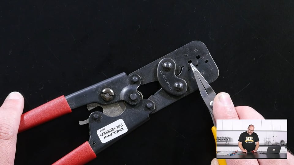
| 17:59 | So the tool we are going to use for that is a open, well I call it my open barrel splice tool here but it is just another general purpose crimp tool. |
| 18:07 | But it's got much thicker dies, and that gives it the rigidity that it needs along with this leverage mechanism which gives you the mechanical advantage that you need to really easily perform that splice join. |
| 18:22 | And those thicker jaws give you the rigidity for the actual tool not to flex, to make sure all the pressure you're applying is actually getting put into the splice and not being soaked up by the rest of the tool. |
| 18:33 | Now this tool here is a, well we've got the Delphi part number here, it's actually made my a company called Sargent tools and it's a, I think it's a CT3137. |
| 18:44 | But I'll put that detail up in that forum post as well. |
| 18:47 | We do also have it in the wiring fundamentals post where we go through all the materials used in that course. |
| 18:54 | 'Cause this is a really really good tool to have and when you're undertaking these splice joins it is definitely my go to. |
| 19:01 | When it comes to choosing the size of general purpose, the size of these dies we're going to use on the end here for ur general purpose tool, it is sort of a trial and error case. |
| 19:12 | You're gonna wanna undertake a few test crimps and observe how they've gone and you're gonna see pretty quickly whether you've got the right size die for the application. |
| 19:24 | What you're going to find if you choose a die size that's too large is that that crimp's going to be loose and it's actually going to pull off the wires very very easily. |
| 19:33 | If the die size you've selected is too small, it's going to be very very difficult to actually crimp. |
| 19:39 | You could possibly end up damaging the tool and it's going to almost shear the open barrel crimp in half. |
| 19:46 | Quite often you find you're left with big ugly burrs on the bottom of the open barrel splice and they can actually, they will actually pretty easily fracture at that point and just come straight off the wires. |
| 19:58 | I know from experience with my middle size splice here, the size die I'm going to use is the A size die on the end here. |
| 20:06 | It's perfect size for the application, does a really really good job. |
| 20:09 | So as I mentioned these are the most common size of splice, which has just completely disappeared. |
| 20:19 | OK we'll grab another one 'cause that one's not coming out of there, I hope that's not gonna cause us any issues. |
| 20:24 | So as I mentioned, these are the most common size of splice we're going to use, so that is the most commonly used jaw on this tool as well. |
| 20:32 | So this tool really does see an awful amount of use when we're undertaking a complete harness build. |
| 20:38 | So what I'm gonna do is get that installed in the end of the tool there, and because this is a ratcheting tool, what I can actually do is put a good amount of pressure, a reasonable amount of pressure on those handles, and because it's ratcheting it's actually gonna keep itself in position, and that's gonna keep my splice nicely installed in the end of the tool here. |
| 21:02 | That's going to be really important, as splicing is one of those jobs, as a lot of jobs when you're building a wiring harness, that'd be really handy to have a third hand for. |
| 21:12 | So the next part of the process as you can imagine, is I'm going to get my wires lined up here, I'll just get this in the overhead shot. |
| 21:20 | And I'm going to have to get these five wires all installed into this open barrel splice. |
| 21:25 | Now it would be really really tempting at this point to grab all those bits of wire and twist them together. |
| 21:31 | You don't want to do that however as what you do when you do that is you actually increase the overall diameter of the bundle which can make it harder to get into that open barrel splice and you actually end up putting quite a bit of strain on the point right where the insulation ends and the copper conductor strands begin and it can give you a place where fractures can occur. |
| 21:50 | So instead we're simply going to pinch those together and get them as tight as we can, and then we're going to maneuver them into our open barrel splice which is sometimes easier said than done and definitely don't be afraid to take a few bits at it if needs be. |
| 22:08 | You will get better at this, the more splices you undertake. |
| 22:15 | Come on, there we go. |
| 22:18 | All in place. |
| 22:20 | So you can see I've got all five of those wire in there now. |
| 22:24 | And having a look at the other side we can see all our copper conductor strands protruding as well. |
| 22:28 | So we wanna do a good visual inspection on both sides of this before we crimp this to make sure we've got full copper engagement in there, as we did go to quite a lot of a process to size this splice. |
| 22:40 | So the procedure now is simply to squeeze down on the handles and undertake that crimp operation. |
| 22:48 | And withdraw it from the tool. |
| 22:51 | So luckily that open barrel splice which is now I think permanently part of this tool didn't cause us any issues there. |
| 22:58 | So we'll head over to our macro shot and have a look at the details of this crimp join and talk about the important parts. |
| 23:06 | So you can see the open barrel splice here has been really nice and evenly folded over, we've got contact down the middle and it's a little bit tricky to see, but on either end of this splice we've actually got a little bit of a bell mouth as well. |
| 23:22 | Now that's an artefact of the actual shape of the dies on that tool, and it's really important as it softens the transition between our splice join here and our stranded copper. |
| 23:31 | And that really helps reduce any possible fatigue cracking that could happen. |
| 23:38 | We can see we've got our copper conductor strands protruding from the end here and it's a good way of being able to do a good visual inspection, make sure we did have all of those wires in there. |
| 23:51 | Now we would, what we would do now in this situation is we would actually take a section of our raychem SCL heat shrink and we would shrink that down onto this piece of harness and then close off the end with some flat nose pliers, and that's going to electrically insulate this splice join from any other wires or any other, the connector body, or anything else in the harness there that it could possibly short out on. |
| 24:20 | However we're not going to undertake that immediately. |
| 24:23 | So the next thing we're gonna have a talk about is professional, how we perform that same sort of splice application but at the professional motorsport level, and the differences that you need to be aware of when you're undertaking splices at that level and with Tefzel wiring. |
| 24:40 | We are gonna be having the standard Q&A session at the end of today's webinar so I would say that now would be a really good time to start firing any of those questions through and the guys will pop them up for me and we'll get to answering those in a moment. |
| 24:53 | Just gonna have a quick look at my notes here again. |
| 24:59 | Make sure we haven't missed anything, no, we're all good. |
| 25:03 | Right so when we get to performing the same splice joins like we've undertaken here but at a professional motorsport level, we're going to use a slightly different type of splice. |
| 25:14 | It's what's know as a closed barrel splice. |
| 25:17 | So I'll actually just get one out here and we'll have a look at it under that macro shot. |
| 25:22 | And it's gonna be pretty obvious immediately what the main difference is. |
| 25:29 | So heading over to that macro shot, so this is what is known as a closed barrel splice. |
| 25:36 | In particular these are made by TE again, and they size them, there's three different sizes of them, they come in a red band, a blue band and a yellow band. |
| 25:47 | That's in order from smallest to largest. |
| 25:50 | There is a really good PDF document on these particular splices which are called mini seal stub splices. |
| 25:57 | And there is a link to that in the webinar section of our forum as well, this is a thread about today's webinar up there. |
| 26:05 | So the key differences we're looking at here are the most obvious one is that this is a completely encased circle. |
| 26:11 | It's not an open barrel, it is a closed barrel and that is why it is called such. |
| 26:17 | When it comes to the actual performance of these splices, I haven't noticed a huge difference, in fact I would go so far as to say that I haven't actually noticed any difference whatsoever in their electrical performance or actually in their reliability. |
| 26:31 | But using a splice like this does get you one very important, one very important piece of information and that's actually traceability. |
| 26:40 | So these splices are supplied with a specific batch number that they come from, which you can include in your documentation, meaning if you ever see any issues with the closed barrel splices that you've used, over say a section of harnesses that you might have built, you can go back and refer to the specific batch number that they were all from and you might actually find that they were possibly from a batch that ended up being recalled or rejected, and it might give a bit of an explanation as to why a section of harness that was built had failures. |
| 27:12 | That being said, I have never had a failure with a closed barrel splice like this, but when you are building harnesses to a professional motorsport standard, that level of traceability is going to be expected to be included in the documentation, so it can be really important. |
| 27:29 | For using these splices, it is very much a almost rinse and repeat of the process we've just gone through with our open barrel splice there. |
| 27:39 | We're going to calculate the size of splice that we're going to need. |
| 27:43 | So as I mentioned, there was the red, blue and yellow sizes. |
| 27:47 | Red spans CMA from 304 to 1510, blue is from 1058 to 2680, and yellow is from 2375 to 6755. |
| 28:00 | Once again, you're not gonna remember all that information now but it is in the document that we've given you a link to in that forum post. |
| 28:08 | And you're going to go through exactly the same process with determining the CMA of the wire you're going to be using, which in this instance is more than likely going to be Tefzel wire. |
| 28:18 | So you might have some slightly different CMA values to what we would find in a club spec harness and that's going to give you the right size splice that you're going to want to use. |
| 28:28 | From there it's the same situation of getting that splice installed into our crimp tool. |
| 28:35 | Once again on that theme of traceability, the tool that you're going to use with these open barrel splices is no longer going to be a general purpose tool, it is going to be a specific tool for this specific application and I would say no other application. |
| 28:51 | It's going to be a tool dedicated to the specific splices and you're not going to use it anywhere else in your harness really as it is going to be for just this one purpose. |
| 29:02 | TE specify a particular tool for this. |
| 29:06 | Which is the AD1377. |
| 29:11 | I know that it is actually exactly the same tool as the Sargent 3137CT that I have here, it is just manufactured by Sargent for TE and the rebadged. |
| 29:22 | So this is most definitely the correct tool to be using in this application. |
| 29:27 | As you can see, the actual handle structure and the leverage mechanism is exactly the same as our general purpose tool there which is to be expected as they're actually made by the same company. |
| 29:39 | One difference, so the main difference with this tool is in the die shapes here, and it's very nice of them to actually include the colours so you know what size die you're going to be using as well. |
| 29:51 | If you read through the documentation for this tool, it is actually quite interesting as they specify that it's not meant to be calibrated by the end user, but then a couple of paragraphs below that they specify that when you get the tool, you should calibrate it using a go, no go gauge. |
| 30:07 | So when you buy this tool you are going to be supplied a gauge that's going to fit in here when the tool is in its closed position. |
| 30:14 | If you can get that go, no go gauge, if it fits in, on the go side, but doesn't fit in on the no go side, when you've got this tool in the closed position, then you've got it calibrated correctly to give the correct amount of crimp pressure at the end here. |
| 30:31 | The way you calibrate this is actually with this nut here, you undo that and you can move the last ratchet point, so that's the amount of pressure you need to put on those handles before that ratchet releases and you can release your crimp out of the join there. |
| 30:48 | Right so you might be asking, why don't we simply use the closed barrel splices all the time? As I mentioned, I haven't actually found them to perform any better electrically or in a reliability standpoint in that matter. |
| 31:04 | They are far more expensive than our brass open barrel splices. |
| 31:09 | I typically buy brass open barrel splices in quantities of about 1000, and they're usually less than, I would say one to two cents each. |
| 31:18 | So they're very very cheap to buy in large quantities and you can always make sure that you've got quite a good supply on hand. |
| 31:26 | That's not the case for our TE closed barrel splices. |
| 31:31 | This single yellow band stub splice there is probably about $5 worth. |
| 31:36 | So if you're undertaking say 20 splices in your harness and you're doing it all with the closed barrel splices there, you could be getting upwards of $100 in just splices, just the materials to undertake that splicing in your harness, not to mention the fact that you've got this specific tool that you're only going to be using for that application. |
| 31:58 | Whereas with our brass open barrel splices and our general purpose tool that you do use in a couple of other applications as well, it is more cost effective. |
| 32:06 | But as mentioned you're not going to get that traceability. |
| 32:09 | So when you get into the realms of professional motorsport wiring harness construction, and you're giving that level of traceability to all the materials that you've used, there really is no other option but to be using those closed barrel splices. |
| 32:24 | Now there is, I didn't show an example of it, but we did talk about sealing our open barrel splice here using some raychem SCL. |
| 32:32 | Part of the TE miniseal range of splices are actually specific sealing boots that get shrunk over these. |
| 32:43 | I don't actually have one to show unfortunately but they look very very much like a solder splice if you've seen one of those. |
| 32:52 | They're a transparent blue heat shrink. |
| 32:55 | They've got a coloured ring in them that lets you know you're using the right size for the size splice that you're using and the benefit of them is that they've got a little bit more flexibility once they're shrunk down, but they've got a good sealing bead at either end and they're actually going to ensure that the wires going into that splice are completely environmentally sealed. |
| 33:15 | There is one step further and they actually provide sealing solder, sealing sleeves for the splices that have got individual holes at one end that you can feed the individual wires through. |
| 33:29 | Then when you shrink it down it really is going to completely environmentally seal that splice away. |
| 33:37 | Rightio I'm just gonna have a quick look at my notes and make sure we've got everything that I wanted to talk about there. |
| 33:44 | Yep we have, right so hopefully that's gonna give you a really good idea of how to correctly undertake a splicing operation in your harness. |
| 33:52 | And what you really need to know for the club spec modified street car level and our professional motorsport wiring harness level as well. |
| 34:02 | Just gonna have a quick drink and then we'll get into the Q&A. |
| 34:11 | Rightio Lepantain has asked what about solder sleeves? Yes really good point, I've got a couple of solder sleeves here, if we just pop to that overhead shot we can have a look at that one. |
| 34:22 | So actually a moment ago when I was talking about those sealing sleeves for the splices, they actually look identical to this, except they don't have the solder band in the middle. |
| 34:31 | So solder sleeves like this, in case you've never seen one before, the way they work is you insert your wires in either end and you heat them up with a heat gun, this solder is, this red band here is actually a solder band and it's a low melt solder that melts at a lower temperature than ordinary say 60/40 tin solder. |
| 34:51 | So it will melt and flow onto the wires, the copper conductor strands in either side and bond everything together, and when the actual red colour there disappears is when you know you've got enough heat into it to flow the solder adequately. |
| 35:05 | The whole thing is heat shrink as well so it all shrinks down, these sealing beads at either end melt and seal everything together. |
| 35:12 | So they would seem to be a really good option for splicing our wires together. |
| 35:16 | However what you will find is it's actually reasonably tricky to get your wires inserted and get it over the heat gun and make sure that you've got that, all those wires totally inserted when it shrinks down and that solder actually flows. |
| 35:32 | They're not really for the purpose of splicing one wire out to multiple wires, I'm not saying you can't do it and it won't be reliable, I'm just saying they're more, where I use them is for splicing to the shielded braid of a shielded cable. |
| 35:47 | You bare back a section of that outer jacket to expose the shielding braid, this goes over the top of that, you insert your one wire that needs to connect, and then shrink everything down. |
| 35:57 | Because you've only got the one wire in there, it's much easier to keep everything really accurately lined up when you're undertaking that heat shrink operation and they are really good for that purpose. |
| 36:07 | Craig has asked, crimping splice joints, engine side or chassis side, which is better? Right good question, and it is one that we do get asked a lot. |
| 36:16 | So I'm going to say typically chassis side I like to do for a harness that is a one piece harness where it comes into the interior and then goes through to the engine bay, it'll probably go through a sealing grommet. |
| 36:32 | The reason for this is that I can locate all those splices in one place, that it's probably going to be quite easy to perform any repairs to, if that's ever needed and you're going to know where all those splices are and then you're going to know exactly how big that harness is going to be through its main trunk section which is typically going to be heading away from the ECU, that is going to be the biggest part, it's never going to get any bigger than that. |
| 36:54 | That actually makes it much easier to install your heat shrink sheathing as well and get everything nice and tidily branched out. |
| 37:01 | The other situation is where you're using a bulkhead connector. |
| 37:05 | So this is connecting your ECU harness up to the bulkhead and then a connector will connect on the engine bay side to head out to the engine. |
| 37:13 | In that situation I'm probably going to look at the number of pins I've got available on that connector and that's probably going to make a lot of the decision for me. |
| 37:23 | For something like a sensor ground pin, the other thing I'll take into consideration is the length of harness on the interior side where it goes back to the ECU. |
| 37:33 | If that needs to be say a metre long, I might not want a single metre long section of 22 gauge wire taking the current from every sensor in the engine bay. |
| 37:43 | It could actually end up giving us a little bit of a voltage drop across that. |
| 37:47 | That might actually not be a problem if all our sensors are exposed to that same voltage drop but it's still something you best want to avoid if possible. |
| 37:55 | In that situation what I'm likely to do is take my single sensor ground wire, splice it out to all the sensors immediately and just bit the bullet of having to run that single sensor ground circuit through multiple pins in that bulkhead connector. |
| 38:11 | If we're talking about power wiring, I can be possibly a little bit more flexible on this. |
| 38:18 | I do quite often take say an injector power supply wire out through the harness in a larger gauge, say 18 gauge for example and splice it out to the four or six 22 gauge wires that might head down to the injector at the point where the harness branches out. |
| 38:36 | It will, one thing that will never change though is you're definitely always going to locate that splice point below a boot of the harness. |
| 38:45 | It's either going to be at a transition point or a connector boot for that extra strain relief that it's going to give. |
| 38:52 | Mike Dizzle has asked where would a multi wire splice be used on the harness? So that's a really good question, we've gone through the example that I like to talk about 'cause I think it's the easiest one to understand is most performance aftermarket ECUs have got one sensor ground pin and you need to splice that out to all the individual sensors in your engine bay. |
| 39:14 | It will, just off the top of my head for example, it might either head to our MAP sensor connector, intake air temp, engine coolant temp, throttle position and possibly many other sensors as well 'cause they all need to share that reference ground level. |
| 39:30 | Power supply wiring, you're going to be splicing in there an awful lot. |
| 39:34 | And that's typically why when I'm building a harness the power supply wiring side is the first part of it I build 'cause there are the most number of splices in there. |
| 39:43 | Sensor supplies, you really are going to be undertaking a lot of multiple wire splicing when you're building a harness. |
| 39:49 | Pedro has asked, there's some important differences between closed and open barrel splices? The differences you're going to see, from my perspective, my experience of using them, I've not seen a difference in electrical performance, so that's conductivity, and I've not actually seen a difference in reliability either but that traceability aspect is absolutely crucial at a professional motorsport level, so you can attach that to your documentation. |
| 40:21 | Because if something goes wrong and it gets traced back to a splice join and that costs a race day, that could be 10s of 1000s of dollars down the drain and they're going to want an explanation for that, so you're going to need that traceability through your documentation to be able to find that explanation. |
| 40:39 | Peter Parker has asked, is the wire alloy composition important and is this available for the wire that you use, is there a preference? The wire that I use, it comes down to two types, it's TXL wire like this which is pure copper wire, as far as the strands inside. |
| 40:59 | The Mil Spec or Tefzel wire is, it's still copper but it is actually tinned or tin coated. |
| 41:09 | I'm going to say no it's not going to matter when you come to splicing it as you are going to put the whole system under enough pressure that it is going to essentially all be cold welded together. |
| 41:22 | Boost Tuning has asked, do you use a different insulation stripper for Tefzel and PTFE? Absolutely yes we do. |
| 41:29 | Give me two seconds and I will grab it out because I know it is just under here. |
| 41:36 | I've actually got two that I would use. |
| 41:38 | So we've got our Ideal Ergo Elite, this is the one I like to use the most as it's really ergonomic as the name says. |
| 41:47 | There's also the Ideal Custom Stripmaster Lite so I'll just get those both under the overhead shot here so you can have a quick look at those. |
| 41:55 | The difference and the reason that we choose these specific tools actually comes down to really precise sizing of the dies here. |
| 42:04 | It's really important when you're dealing with Tefzel wire because the insulation is so thin and quite tough as well, that when you strip it, you go through only the insulation and you don't end up going too far and nicking those copper conductor strands or even breaking them off. |
| 42:21 | Once again when we get to the professional motorsport realm where we're using that wire, individual strands can make a difference to a successful crimp join, particularly when you're pinning autosport connectors. |
| 42:33 | The size you're going to use on the positioner is related to size of wire you're got in that terminal not to mention the terminal itself. |
| 42:41 | And if that wire going into that terminal doesn't have the expected amount of copper, it might end up giving you a slightly unreliable crimp join. |
| 42:49 | So for that reason, these are the only tools that I will ever use in a professional motorsport level because they're the only ones that are specified for the job and that I find to be 100% reliable. |
| 43:04 | Jelala's asked do you need to worry about any sort of voltage drop at the splice? I'm going to say no, that's going to come down to the rest of your design procedure, what I would find is that because we have put the splice join under so much pressure and those copper conductor strands are all essentially cold welded together, you can think of that as being one continuous piece of wire now. |
| 43:29 | If you wanted you could measure the voltage drop across there, but I would suspect you're going to need a very very accurate voltmeter or a way of actually pumping quite a lot of current through that wire to get the measurable voltage drop across it. |
| 43:42 | Performing splice joins like this I've found to be completely reliable in terms of electrical performance. |
| 43:51 | Mike Roan has asked, be very interested in a link to the seal that I talked about with provisions for each individual wire. |
| 43:57 | You are in luck if you head to the HP Academy forums, the webinars section, there'll be a post right up the top that says 189, there is a link to the TE PDF about these Superseal splices here, and that actually has information on those solder seals that have got the individual wire holes in them. |
| 44:21 | Bellotech has asked trigger wires like trigger one and trigger two, do you pass them also in the bulkhead connector? Absolutely but I think the question that you might be more referring to there, the one that we get an awful lot, is what do you do about the shielding braid for that wire when we have to head through a bulkhead connector? What you do is you actually splice a standard piece of wire to the shielding braid, it's a technique we go through in our practical wiring course actually in quite a lot of detail. |
| 44:54 | Show a couple of different methods of doing it, both the club spec way and also using these solder splices as well. |
| 45:02 | And then you're going to pass that wire that's connector to the shielding braid through the bulkhead connector on a separate pin, so it gets its own dedicated pin for the task. |
| 45:13 | On the other side of the connector, you're then going to very shortly after that connector, splice it back into the shielded braid. |
| 45:20 | You're gonna wanna keep the minimum amount of unshielded section of wire there. |
| 45:27 | If we were talking about genuine Mil Spec or military applications, you would probably be using connector bodies that are capable of actually being connected to a shielding braid and then the connector body forms part of the whole faraday cage that's around the wire that's actually absorbing any noise and draining it away to ground. |
| 45:50 | The autosport connectors that we use in professional motorsports don't have that facility, however with where we locate them up on the bulkhead, the electrical noise you see up there normally isn't huge, a lot of it is actually dampened down by the firewall itself and the connection from that metal bodied connector to the firewall so you don't typically see any problems with noise getting into the system there. |
| 46:17 | But to summarise, yes you absolutely pass a shielding braid through on its own dedicated pin so you do need to make allowances for that when you're specifying the number of pins you need on that connector. |
| 46:29 | Rightio that's actually brought us to the end of our questions. |
| 46:31 | Thanks heaps for tuning in today guys. |
| 46:34 | I really hope that's given you a good idea of what's involved in performing really nice reliable splice joins to make sure your harness is gonna be totally reliable when it's in service and where we actually place those harnesses, where we place those splices in the harness as well. |
| 46:52 | So thanks heaps guys, I really look forward to catching you on the next one. |


