218 | What is a Pull Up Resistor?
Summary
If you’re using a two wire thermistor for temperature sensing then you’re ECU is going to need a pull up resistor in order to be able to convert the variable resistance of the sensor into a voltage that it can interpret. Most often the pull up resistor is an internal part of the ECU and doesn’t require us to think too much about it, however in some instances we may need to fit this pull up resistor externally. In this webinar we’ll discuss what a pull up resistor is, how it works, and show you how you can add your own external pull up resistors when necessary.
| 00:00 | - Hey guys, Andre from High Performance Academy, welcome along to another one of our webinars. |
| 00:04 | Now this time we're going to be talking about a topic that kind of crosses over between both wiring as well as engine tuning. |
| 00:12 | We're going to be talking about the topic of pull up resistors. |
| 00:14 | And this isn't a particularly complex topic but if you don't understand what a pull up resistor is, how it works and how to properly work with a pull up resistor in your chosen ECU, then you can set yourself up with a few potential problems. |
| 00:29 | Particularly with the likes of digital inputs and if you are going to be adding in a two wire analog temperature sensor into your ECU, you're also going to need to know about these. |
| 00:42 | As usual, with all of our webinars, if you've got any questions while I am presenting here, please feel free to ask those in the chat and the team will transfer those through to me and we'll deal with those questions at the end. |
| 00:54 | So I think we probably should start off with what is a pull up resistor and why do we need one? So in general there are two areas that we will use a pull up resistor. |
| 01:05 | One is where we have a digital input. |
| 01:08 | So let's say for example a driver controlled switch inputting to a digital input pin on our ECU. |
| 01:16 | In this case, and we'll talk about this in a little bit more detail shortly, in this case the pull up resistor is necessary so that the ECU can distinguish between the switch position. |
| 01:25 | Whether the switch is switched to ground or whether it's in the open position. |
| 01:29 | Without the pull up resistor, when the switch is in the open position, the voltage that the ECU will see is going to be undetermined, it's going to be floating so means that without the pull up resistor the ECU can't tell if the switch is open or closed. |
| 01:44 | Now I've just talked about a switch but there are also digital input sensors used for the likes of engine position and engine speed which are in exactly the same situation, they switch between a low voltage and a high voltage and some of these will also need the pull up resistor. |
| 01:58 | Likewise if you are dealing with an analog temperature sensor, so I've got a couple of these here. |
| 02:06 | We'll just have a look at these under our overhead camera. |
| 02:08 | So this is a fairly standard Bosch air temp sensor. |
| 02:14 | It uses the two pin EV1 style injector plug. |
| 02:17 | And then we've got a slightly more modern 1/8th MPT fluid temperature sensor. |
| 02:24 | The thing you can see, particularly with this one here is that it has two wires on it. |
| 02:29 | And this is important with a temperature sensor like this, they're referred to as a negative temperature coefficient thermistor. |
| 02:38 | And they don't output a voltage which our ECU needs to see in order to decide what the temperature is. |
| 02:45 | Instead what happens with the NTC sensor is that the temperature will affect, will result in the, excuse me, I'll just get this up on the screen so I can show you. |
| 02:57 | The temperature change will result in the resistance of the sensor changing. |
| 03:02 | So it's the resistance that actually changes not the voltage but the ECU doesn't detect that resistance. |
| 03:08 | So we need a way of converting that change in resistance into something that the ECU can understand as a variable voltage. |
| 03:15 | So while I was messing around there, let's just jump across to my laptop screen for a second and we'll have a quick look. |
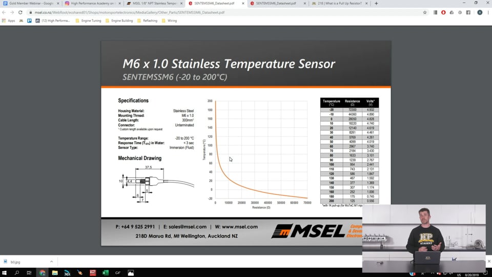
| 03:21 | This is the data sheet from Motorsport Electronics who produced that little 1/8th MPT sensor that I just showed you. |
| 03:28 | And there's a couple of bits of information that are important on this sheet here. |
| 03:32 | But for a start what I wanted to just show you is that this graph here represents the change in resistance with the change in temperature. |
| 03:40 | So you see quite a large non linear variation in our resistance as the temperature changes and of course there is a little data sheet over here that shows you exactly what that resistance will be at each particular break point for temperature. |
| 03:55 | Alright so how do these work and why do we need them? So first of all what I think we'll need to do is head across to have a look at a diagram here of how the circuit looks for a digital switch. |
| 04:09 | So this is a driver controlled switch which I've already talked about. |
| 04:12 | So here on the right hand side we've got our ECU. |
| 04:15 | We've got our switch which is represented here by this broken circuit and one side of the switch is connected straight to a zero volt. |
| 04:25 | So generally this will be connected to a sensor zero volt circuit on our ECU and then we've got the other side of the switch which we can see here is connected to the digital input pin on our ECU header. |
| 04:37 | Now the problem is here that if we forget for a moment about this little circuit here which is our pull up resistor. |
| 04:44 | Without that pull up resistor, when the switch is open or closed the ECU can't distinguish between that difference. |
| 04:51 | When the switch is closed it's going to switch to zero volts. |
| 04:54 | But we need a change in voltage when the switch is open so that the ECU can detect or sense that. |
| 05:01 | So this is where our pull up resistor comes in. |
| 05:04 | Now this is being drawn externally. |
| 05:07 | So pretty obvious there, it's outside of the ECU. |
| 05:09 | The reality is that most aftermarket ECUs on the digital inputs will have a software selectable internal pull up. |
| 05:17 | So we don't actually have to do any wiring here and this will all be controlled electronically, it's all held inside of the ECU. |
| 05:25 | But still the circuit is still going to show us what happens here. |
| 05:29 | So one side of the pull up resistor here, where it goes into the ECU header plug, this will be connected to plus five volts, I'll try and draw this without making a mess of it, there we go. |
| 05:42 | That actually looks pretty tidy, happy with that. |
| 05:43 | So we've got plus five volts going on there. |
| 05:46 | And in this case if we've got plus five volts on one side of the resistor and we've got our switch open here, what of course is going to happen is that when the switch is open, five volts will also be present at our digital input pin. |
| 05:59 | So in the open position, the ECU is going to see the input on that circuit at five volts. |
| 06:06 | Of course when we close the switch here, this completes the circuit, the circuit will go to ground and we'll end up with our voltage at that pin on the ECU at zero volts. |
| 06:17 | So this is what is causes, the pull up resistor creates a difference in the voltage that the ECU will detect when the switch is in the open or closed position. |
| 06:27 | Now the pull up resistor, while there isn't a fixed resistance that must be used, generally the resistor that is favoured is the one kiloohm or 1000 ohm resistor. |
| 06:38 | So what this also results in is a really small amount of current in that particular circuit so that's why when we switch to ground, we're going to end up with that voltage dropping straight to zero volts. |
| 06:50 | So we're going to have a look in an ECU just to get an example of what that actually looks like in the tuning software in a moment but as I mentioned, that's one use of the pull up resistor. |
| 07:02 | The other use of the pull up resistor is where we are going to be using a negative temperature coefficient thermistor, our two wire thermistor that we've already looked at. |
| 07:12 | So what we'll do is have a look at that particular circuit. |
| 07:16 | So pretty much exactly the same. |
| 07:18 | In this case, what we've done is we've taken our switch out of the circuit and we've added in our little Bosch air temp sensor there. |
| 07:24 | So what this does is it creates what's called a voltage divider circuit. |
| 07:29 | So we've essentially got a resistor here and we've got a resistor here. |
| 07:35 | And this controls the amount of current flow between the five volt pin at the ECU and the, it's going obviously to ground at the other side. |
| 07:45 | So what we end up now with is a variable amount of voltage depending on the resistance of the thermistor. |
| 07:52 | So what I'm actually going to do, I think I can probably draw this slightly better, that's going to give you a slightly better idea of how that will look. |
| 08:01 | So just bear with me for a second while I do this. |
| 08:04 | So what we'll have is our resistor here and this will be our one kiloohm pull up resistor. |
| 08:13 | Then we come down to our thermistor which I'll just draw in here. |
| 08:18 | In the middle here we've got our voltage out to our ECU and then we're going to have this connected to ground. |
| 08:27 | So again I'll just try and quickly draw this in, so we've got five volts here. |
| 08:35 | We've got our 1K pull up resistor here. |
| 08:40 | And this is our, let's say it's an IAT sensor. |
| 08:45 | Horrible drawing I'm sorry. |
| 08:47 | And then finally we've got our output here to our ECU. |
| 08:51 | So how this works, it really comes down to the real basics of electronics which is ohm's law. |
| 08:58 | So this is with ohm's law we need to know our voltage and our resistance and we can work out the current flow in that circuit. |
| 09:06 | And then once we know the current flow, we can work out what the voltage is going to be at the ECU. |
| 09:13 | So V=IR, so if we've got five volts there and we've got our one kiloohm resistor, our one kiloohm pull up resistor and then we've got our intake air temp sensor. |
| 09:25 | If we add those two resistances together, obviously the air temp sensor resistance is constantly changing. |
| 09:32 | But if we add those together we're going to be able to find out what the current flow through that entire circuit is. |
| 09:37 | So we're going to be able to get our current flow from our five volt sensor supply voltage down to ground. |
| 09:44 | Once we know what our current flow is, we can then use ohm's law again to find out again what the voltage across, oops that wasn't very clever of me. |
| 09:52 | We can find out what the voltage across our intake air temp sensor is going to be and that is the voltage that our ECU will find. |
| 10:00 | Now to make that a little bit clearer as well we're going to go through the process here of just showing you how that all works, how ohm's law works. |
| 10:10 | So we'll head across to my laptop screen here again. |
| 10:13 | And in this case the sensor that I just showed you from Motorsport Electronics has this nice calibration table here with all of the data that we're going to need. |
| 10:23 | We've got our temperature, we've got our resistance and we've got our voltage. |
| 10:27 | However in some instances we are not going to know, sorry what I should say, in some instances that data won't be presented with voltage as well. |
| 10:37 | Instead what we'll get is simply temperature and resistance. |
| 10:41 | And in a lot of ECUs we don't get the ability to directly enter resistance. |
| 10:46 | Instead the ECU is interested in the voltage that it's going to see. |
| 10:50 | So we need to actually create that information ourselves. |
| 10:54 | I am getting a little bit ahead of myself though, I just want to jump back a step. |
| 10:59 | I'm going to show you in excel how we can generate that voltage data. |
| 11:02 | Basically replicate that table. |
| 11:04 | But first of all let's just actually have a look at the options that are available for getting one of these air temp sensors or analog temperature sensors into an ECU. |
| 11:14 | So we'll head into our tuning software here. |
| 11:17 | And what we're going to do is have a look at our options for input. |
| 11:21 | So when it comes to inputs we've got the ability to have analog inputs. |
| 11:26 | So we'll open up our analog inputs. |
| 11:28 | And with our analog inputs we've got four, in this case, analog temperature sensor inputs. |
| 11:36 | And then we've got a range of analog voltage inputs. |
| 11:38 | In this case we've got 12 analog voltage inputs. |
| 11:40 | Now the thing that differentiates between an analog temperature input and an analog voltage input. |
| 11:47 | And this goes for the majority of ECUs, is that the analog temperature sensor inputs, unsurprisingly, as their name would suggest, is designed for directly connecting up to one of these negative temperature coefficient thermistors. |
| 12:00 | So what it does, for that very reason is it has a built in pull up resistor inside of the ECU so that 1K pull up resistor that we just looked at the circuit for, that will be housed inside of the ECU. |
| 12:14 | On the other hand the analog voltage inputs are more usually used for a sensor that already outputs a variable voltage. |
| 12:21 | Maybe a MAP sensor, maybe a throttle position sensor. |
| 12:25 | Any sensor essentially that will give a zero to five volt signal. |
| 12:28 | So for that sort of sensor, a pull up resistor is not necessary, that's all done by the sensor, you give the sensor five volts, you give the sensor a zero volt reference and depending on the conditions that the sensor is exposed to, it will output directly a variable voltage to the ECU. |
| 12:45 | So let's have a look here at our AN temp 1 input and we'll have a look at our options there. |
| 12:52 | So we can see that at the moment, that is selected to be off. |
| 12:56 | We're going to set that up and for the moment let's call that our gearbox oil temperature, we can choose that from our drop down menu. |
| 13:04 | So let's choose that option and this will give us, all of the other options will now become available. |
| 13:12 | So we can set an error voltage level, so this is just some diagnostics, if the circuit is open circuit or closed, or straight to ground, it will trigger a high voltage or a low voltage warning. |
| 13:24 | And in both of those situations we can also select what the default value will go to, in this case 150c. |
| 13:31 | Now this is the important part for us though, we can see that we have a pull up resistor. |
| 13:37 | In this case one kiloohm internal is selected. |
| 13:40 | We can double click on that and we've got a range of options here. |
| 13:43 | We've got either a 1K or a 10K internal, or alternatively you can add your own external pull up resistor and in this case the ECU will disable the internal pull up resistor and it will do the calculation so that it knows what voltage to expect from the particular sensor. |
| 14:03 | In this case, again while we don't have to have a specific resistor, I'm going to leave that at one kiloohm and we can then go to our sensor type. |
| 14:14 | So for the majority of the common sensors, there will already be a predefined sensor available, however we're going to just have a look here at using a user defined sensor. |
| 14:25 | So this is where we'd have a data sheet like that one we just looked at and set this up ourselves using a cal table. |
| 14:31 | So once we've done that, obviously we then need to input some data into the cal tables. |
| 14:36 | So let's have a quick look at that. |
| 14:38 | So we'll go to cal table one which is what we were using. |
| 14:41 | Now I do apologise because with these changes that I've made, it comes up in red, so a little hard for you to read but the input units, and a nice feature with the Link ECU, we can either choose to set this up in ohms or volts. |
| 14:56 | And that's not always going to be the case but either way basically as long as you've got the data, you're going to be able to calculate as I'll show you shortly, what that's going to come out to be. |
| 15:08 | Then we can choose what the units are for temperature as well as the start point of the table and our increments. |
| 15:15 | And then if we double click on our cal one table, we can then set that up. |
| 15:20 | So remembering again this is voltage, I've actually got numbers in here that clearly represent resistance. |
| 15:26 | Hopefully we're not going to have 65000 volts going into our ECU but once we've got that table filled in with the data from our data sheet, we're going to have a sensor that works. |
| 15:37 | OK so for most tuners, that's about as far as things go. |
| 15:43 | They don't really need to think too much harder about pull up resistors. |
| 15:47 | However you can get yourself into a situation where you've run out of analog temperature inputs on the ECU header plug but you still want to add more temperature sensors into the ECU. |
| 15:57 | And this now represents a problem and this is a situation where you do need to know about pull up resistors. |
| 16:04 | And the reason for this is we can actually repurpose an analog voltage input for the purposes of adding a temperature sensor, but in order to do so, we're going to need to wire in an external pull up resistor to five volts at the ECU header plug. |
| 16:19 | So let's have a quick look at how we would do that. |
| 16:21 | We'll head to our analog voltage settings this time. |
| 16:25 | I'll just load that up and we've got in this case, let's look at our analog voltage input 10 and we'll turn that on. |
| 16:37 | So we've got all of the usual sensors that you would normally see with a analog voltage sensor, MAP sensor, MAF, throttle position et cetera. |
| 16:46 | But if we cycle down we can see we've got the option to add some temp sensors here, so engine coolant temperature, air temperature, general purpose temperature and each of these is denoted with external pull up. |
| 16:59 | So that's just a little reminder that you're actually going to have to do some work here yourself. |
| 17:04 | So let's set up a general purpose temp sensor. |
| 17:06 | We can give this a label so that we know what that's going to be. |
| 17:08 | Let's call this diff temp, that'll probably be fine. |
| 17:13 | And then we've got exactly the same situation here, we've got our calibration that we're going to be using, in this case cal table one. |
| 17:19 | In this case because it is an analog voltage input we are going to be doing that calibration in terms of voltage. |
| 17:26 | And then we've got our high error, our low error and our error value. |
| 17:31 | So once you've got that set up you can then set up your calibration in the ECU. |
| 17:36 | And that temperature sensor will read just as well as if it was going in through an analog temperature input. |
| 17:43 | Now that I've filled in the blanks there we're going to go back to where I was and we'll look at how we can generate the voltage data. |
| 17:51 | So let's just head back across to our spec sheet here. |
| 17:54 | So this column here is what we are going to be trying to create. |
| 18:00 | Now remembering again that this just works on ohm's law. |
| 18:03 | We're going to be calculating the current flow through the circuit and then we're going to be using that current flow, multiplying that by our variable resistance from our temperature sensor to work out the voltage that the ECU will be seeing. |
| 18:19 | And just again we'll have a quick look and show you what that actually looks like. |
| 18:22 | So we've got our five volt source basically here, going through our pull up resistor which is here, then we've got our temperature sensor in the circuit and then finally that is connected to ground. |
| 18:37 | So what we really want to do is basically calculate the voltage in this part of the circuit here which is what the ECU header plug, the analog voltage input, is connected to. |
| 18:46 | So let's head across to my excel spreadsheet that I've got set up here and what I've done is I've just entered the temperature and the resistance values straight from that datasheet that we've already looked at and I've also put in a pull up resistance here. |
| 19:02 | The nice thing about setting this up here is that if you do it like this, you can then choose to change your pull up resistor value. |
| 19:09 | Not too sure that that'll often be handy but you can choose to do that and it will change the voltage calculation for you. |
| 19:17 | So let's see if I can get this right. |
| 19:19 | So what we want to do is start by hitting equals and then we're going to have five volts, so that's our voltage and then we're going to divide that by our total resistance, so we've got the divide sign, we're going to do our open brackets, and then what we want to do is add the two resistances. |
| 19:36 | So for this point it's our 72300 or 72 kiloohms. |
| 19:41 | And then we're going to add that to our pull up resistor value, then we can close our brackets and then that is going to calculate there the current through that circuit at -20 degrees centigrade. |
| 19:53 | What we're then going to do is multiply that out just by our resistance at that temperature, this is our voltage divider remember, we're trying to find that voltage that the ECU is going to see. |
| 20:04 | If we press enter, you can see that gives us 4.932 volts. |
| 20:09 | Now what we're going to do is drag that formula down to fill in the rest of the table. |
| 20:13 | Before we do that I'm just going to make a little modification here using the dollar sign symbol here we can fix the cell for our pull up resistor so that that's not going to go haywire. |
| 20:26 | What we'll then do is highlight the cell with the formula that we want to drag down, drag that down and it'll fill in the rest of the values. |
| 20:33 | So if we now check, let's just take one value here obviously at -20 degrees C, 4.932 volts. |
| 20:42 | We'll head across to our data sheet, 4.932 volts. |
| 20:46 | Now this might seem all superfluous, unnecessary, who cares, you've got that data sheet. |
| 20:52 | But I always believe, regardless whether it comes to wiring, engine building or tuning, that having a basic understanding of what's actually going on behind the values there is going to be really helpful. |
| 21:03 | And particularly if you get yourself into a situation where you've got a data sheet that doesn't have those voltage values, it's really easy as you've just seen to use an excel spreadsheet or Google Sheets to calculate those values. |
| 21:15 | Now the nice thing about doing this here as I mentioned, once we've got that all set up, if we wanted to maybe change our pull up resistor to 10000, we can do that and the voltages will automatically adjust. |
| 21:29 | So really easy to go ahead and do that. |
| 21:32 | Alright we're going to move into questions and answers really shortly but just before I do that, I just wanted to show another couple of bits inside the Link ECU where this pull up resistor comes into play. |
| 21:44 | So obviously we've looked at our temperature inputs here. |
| 21:47 | What we'll also do, excuse me, is we'll just have a quick look at the setup for a digital input. |
| 21:54 | So for example here we've got our aircon request on our digital input one. |
| 22:00 | So we'll head across and have a look at that. |
| 22:03 | So this really comes down to how the sensor switches or how the input switches. |
| 22:08 | In this case you can see that we've got our pull up resistor switched to off. |
| 22:13 | And the reason for this will be that when the aircon request is going into the ECU, rather than the aircon request from the factory car switching to zero volts or to ground, what it'll actually be doing will be switching to a high voltage. |
| 22:27 | So in that case you do need to be careful with your pull up resistor because if you turn the pull up resistor on here, when the aircon request isn't present, we're going to be seeing five volts because of the pull up resistor and of course when the air con request switches on, we're staying at a high voltage so again the ECU sees no determination between the switched on and switched off position. |
| 22:48 | So with a digital input, we're going to need to use the pull up resistor, if we're switching to ground. |
| 22:54 | If we're switching to a high voltage then we do not want to use our pull up resistor. |
| 22:59 | In this instance as well we can also select what voltage level the input will be considered to be on in. |
| 23:10 | The other thing that is important to understand here, let's just head back across to our analog temperature inputs for a second. |
| 23:19 | Is when it comes to our pull up resistors and the fact that with the analog temperature inputs on the Link ECU, these are software selectable. |
| 23:29 | So we've got the ability to turn our pull resistors off. |
| 23:33 | The reason we may want to do this, and this would probably be quite rare, would be the situation where you are installing an aftermarket ECU in a piggyback application where you're piggybacking the factory ECU and you want to share the input signals from the likes of the intake air temperature and the engine coolant temperature. |
| 23:50 | Now in that instance the factory ECU, for exactly the same reason, will have internal pull up resistors on those analog temperature input channels. |
| 23:58 | So if you connect up an ECU and you share that signal, if the aftermarket ECU which you've just piggybacked in, also has a pull up resistor, this is going to play havoc with the values, basically turning them into nonsense. |
| 24:10 | So if you are piggybacking a factory ECU, you can still do that as long as you turn the pull up resistor off. |
| 24:16 | Unfortunately a lot of aftermarket ECUs don't have software selectable pull ups on their analog temperature inputs, they are permanently hardwired in there, so doesn't give you a lot of option unless you want to maybe set up the temperature sensors through an analog voltage input or alternatively you're going to be stuck with adding your own external sensors. |
| 24:40 | Alright that has got us to the end of our webinar. |
| 24:43 | Obviously a pretty simple topic really there, there's not a lot to understand but I just know that there are a few key areas that people still get tripped up on. |
| 24:53 | And particularly that little demonstration there showing you how to convert between resistance and voltage provided you know the pull up resistor value, that in its own right is really powerful to keep in the back of your mind. |
| 25:07 | Alright looks like we don't have any questions there so I am going to call it a day. |
| 25:14 | Hopefully everyone has enjoyed today's lesson and of course as usual if you have got any questions after this webinar has aired, please feel free to ask them in the forum and I'll be happy to answer them there. |
| 25:24 | Thanks for joining us, hope to see you all again next week. |
Timestamps
0:00 - Introduction
0:50 - When do we use pull up resistors?
3:55 - How does a pullup resistor work and why do we need one?
8:00 - Converting from ohms to volts
10:50 - Getting sensors into an ECU
15:35 - Repurposing an analog voltage input for a temperature sensor
17:40 - Generating voltage data
21:30 - Digital input setup
23:10 - Considerations when piggybacking factory ECUs


