230 | Star point earthing explained
Summary
Incorrect earthing is one of the most common issues we face when it comes to diagnosing wiring issues with EFI systems. Some of these issues can be time consuming to find and fix, and of course, time is money. In this webinar we’ll discuss star earthing and find out why we use it.
| 00:00 | - Hey team, Andre from HIgh Performance Academy here, welcome along to another one of our webinars. |
| 00:05 | And today we're going to be covering a wiring topic, we're going to be talking about the topic of correct grounding. |
| 00:11 | And this seems like a simple topic, it's something that I know a lot of people don't really give too much thought to when they are wiring up their aftermarket standalone ECUs or basically doing any modifications to the wiring harness but coming from a background where I owned a performance workshop, tuning literally hundreds of cars every year, grounding or earthing problems were one of the most frustrating issues that we came across, probably also one of the most common issues that we came across. |
| 00:42 | And particularly when you've got a car on a dyno, it can waste a lot of time trying to sort out exactly what's going on, fix these issues and of course time is money when you are on a dyno so this can end up wasting a lot of your money if you do have these issues. |
| 00:57 | The good news though is that if you've got a solid understanding of what's going on, then it's actually relatively easy to do this right the first time around and if you do it right the first time around then you're very unlikely to have any problems going down the track. |
| 01:12 | And this also counts for long term reliability issues that crop up, so you may end up wiring up the car, producing a grounding strategy that isn't actually correct but it may still actually function correctly at the time. |
| 01:26 | However you do then open yourself up as you will find as we go through the webinar for problems that can crop up if maybe one of your earth straps comes loose or maybe becomes a little bit corroded and the resistance of that earth strap increases. |
| 01:40 | So this can bring in really frustrating reliability issues down the track that can be really really hard to fault find. |
| 01:47 | Now I want to be right up front here with this webinar as well and mention that I am going to be using a lot of information in this webinar that's come from Andy Wyatt's tech talk on star point earthing. |
| 02:02 | The reason that I'm going to be doing this is that Andy does an exceptionally good job of explaining it so I'm actually going to be using some of the diagrams from his particular article so I do credit Andy for that information. |
| 02:15 | For those of you who aren't aware of who Andy is, Andy was the owner and designer of Adaptronic aftermarket standalone ECUs. |
| 02:23 | Adaptronic I think last year or maybe late 2018, was purchased by Haltech and Andy is now working for Haltech as an R&D engineer. |
| 02:33 | Of all of the people that I've met in the aftermarket standalone ECU industry, Andy is definitely one of the smartest guys out there. |
| 02:43 | I've got a lot of respect for him and basically if he says something, you can pretty much guarantee that it is technically correct. |
| 02:51 | So the idea behind this is not just a case of explaining to you what you should be doing. |
| 02:58 | I could do that and if you followed what I explain and what I tell you to do, then you're going to get a good result and a reliable earthing strategy. |
| 03:06 | However I always think it's more important to actually have an understanding of why you need to do something, this way you can figure it out for yourself and you've got a better understanding if something isn't right, of the potential reasons around that, rather than just basically copying exactly what I tell you to do. |
| 03:24 | As usual with this webinar, we will be having questions and answers at the end, so if you've got anything that I talk about today that you'd like me to dive into in a little bit more detail, please feel free to ask those questions in the chat, the team will transfer those through to me. |
| 03:40 | So basically we want to start by talking about what the issues can be if we get our grounding or our earthing wrong. |
| 03:47 | And these really come down to two separate areas. |
| 03:50 | The first is that we can end up striking ground offsets which are voltage offsets on the zero volt plane. |
| 03:58 | Basically the ECU uses the zero volt reference for its sensors. |
| 04:03 | So as we'll see as we go through this, this can play havoc with the input from some of the sensors. |
| 04:09 | We can also end up with problems where large current flow is inadvertently run through the grounding on the ECU and in worst case scenario, this can actually end up damaging the ECU beyond repair. |
| 04:23 | Understandably the ECU really isn't designed to handle the high current that we might expect to see in the vehicle electrical system, the likes of when the starter motor is cranking the engine over. |
| 04:35 | So that's our first issue, basically talking about ground offsets, the second one is that we can end up with magnetic field noise which can cause interference and problems with triggering to our ECU. |
| 04:48 | So this is a really big issue that can be frustrating to fault find because if you are running into triggering issues, there can be a variety of reasons that would cause that. |
| 04:59 | So again minimising these problems, which as you'll see, really really easy to do, if we follow some basic protocols, is going to mean that you've got the best chance possible of getting the right result. |
| 05:10 | So let's start by talking about our ground offsets. |
| 05:15 | And what's important to start with here is to understand that every wire in our wiring harness has some level of resistance. |
| 05:23 | So it might not seem that significant but every wire has some level of resistance depending on its diameter, its AWG, its gauge and also the length of that wire. |
| 05:37 | So what this means instantly is if we've got resistance in a wire, if there is current flowing in that wire, we by definition will end up with a voltage drop across that wire. |
| 05:48 | So this is where we get into problems if we've got voltage drops across the wire we can have issues with the reference voltage or ground voltage for our ECU. |
| 05:59 | So there's three examples that I'm going to go through here and I'm going to try and explain to you and we'll see how the grounding strategy that we use can affect things. |
| 06:11 | So what we'll do for a start, we'll just head across to my laptop screen here. |
| 06:15 | And we've got a basic wiring diagram here so we've got our car battery here. |
| 06:21 | We've got our ignition switch, we've obviously got the engine here and then we've got a situation where first of all there is a ground strap which runs from the engine block to the battery negative. |
| 06:37 | It might not necessarily go straight from the battery to the engine. |
| 06:42 | Quite often you'll find it'll go through the chassis but for simplification that's what we've got. |
| 06:46 | We've then got a situation where we have another earth strap or power ground I should say that runs to our ECU. |
| 06:53 | And then we've got another power ground here that runs from our ECU to the battery negative. |
| 06:59 | So this is a way I do see occasionally an ECU installed where the ECU is grounded to both the battery negative as well as the engine block. |
| 07:09 | And I know that a lot of people, particularly if they don't really think through what's happening here, think that earthing to multiple points like this is going to be an advantage, it's actually going to do a better job. |
| 07:21 | But the reality is that's not the case. |
| 07:23 | So if we look at what's happening here in this diagram, we've got our ignition switch in the crank position so of course when the engine is cranking we've got very high current flow to that starter motor. |
| 07:34 | Because we've got high current flow to the starter motor, that current flow also has to go back through our ground strap here. |
| 07:42 | And what that does is it creates, as we've got in here, a voltage across, a voltage drop across that ground strap and again as I mentioned, that's dependent on the resistance of the ground strap, obviously they should be relatively low resistance, they're going to be a large diameter, large gauge ground strap. |
| 07:59 | But you're going to nonetheless end up with a voltage drop across that ground strap. |
| 08:04 | So then what we end up with is a starter motor current basically can end up sheering or going into the ECU power ground as well. |
| 08:17 | Because both grounds there are at slightly different voltages due to that voltage drop we've got across the ground strap between the engine block and the battery negative. |
| 08:28 | Now again if everything is in good condition, this shouldn't be a massive concern and it is only momentary, it's only happening when the engine, the starter motor is being cranked. |
| 08:39 | The problem is with age or if the ground straps aren't in good condition, we can actually get into a situation where, let's say for example worse case scenario, this ground strap between the engine block and the battery negative falls off, OK that's extreme, maybe it gets loose or in some way it's not able to support the current flow like it's supposed to. |
| 09:00 | So we've now got another current path that's going to end up going through our ECU, back through our ECU to ground. |
| 09:07 | Now again as I mentioned, obviously the ECU is not designed in any way shape or form to support the sort of current flow that the starter motor is going to produce. |
| 09:16 | So of course when that happens, you're going to instantly damage the ECU, most often beyond repair and of course when the smoke gets out, that's going to be pretty expensive. |
| 09:26 | So that's our first situation and showing hopefully there that earthing the ECU to both the battery negative and the engine block is a no no. |
| 09:36 | Now the next example and this is one that Andy from Adaptronic actually used to use as a test for engineers when he was employing new engineers. |
| 09:47 | So this is actually an issue with the Mazda NA6 Miata and it was a factory fault from Mazda and the way they wired it. |
| 09:57 | So here what we've got is our ECU, I do apologise for the quality of these images but hopefully I'm going to be able to explain what's going on here. |
| 10:05 | So we've got our ECU, we've got our, in this case our coolant temperature sensor. |
| 10:11 | So that's obviously providing a variable resistance as our coolant temperature changes and that variable resistance is basically inside of the ECU. |
| 10:20 | Here we've got a five volt supply and we've got a sensor ground so basically as the resistance of that temperature sensor changes, the ECU can detect a variable voltage and it's calibrated between voltage and temperature. |
| 10:36 | Now in the NA6 Mazda, the engineers from Mazda for some unknown reason decided that they would ground the sensor to the engine block as well as the ECU. |
| 10:50 | So basically we can see here that the ground side of this coolant temperature sensor, comes down here and it goes back to our signal ground. |
| 10:59 | But at the same time it also goes back to our engine block. |
| 11:04 | Now I'll just mention here that conventionally when we are wiring up any sensors, that are not grounded to the engine block, so this would be most of the sensors we're likely to run, our typical fuel pressure sensors, oil pressure sensors, manifold pressure sensors, throttle position sensors, these sensors all require a regulated five volt, they also require a sensor ground and then they output a variable voltage based on whatever the pressure or throttle position they're measuring is. |
| 11:35 | So it's really important for reliable results or accurate results from that sensor, that they have five volts at one side and a zero volt reference on the other side. |
| 11:44 | Because the calibration is voltage to whatever, throttle position or manifold pressure, if the five volt or zero volt references aren't accurate then of course the output from the sensor is going to be inaccurate. |
| 11:57 | Now in this situation, under most conditions this actually doesn't cause any real trouble. |
| 12:03 | But at higher RPM because we've got a higher injector duty cycle, basically the ECU is needing to sync more current through its power grounds than it would at low RPM or idle. |
| 12:17 | What we end up with is a voltage drop across the power ground. |
| 12:22 | Now what this does then is it ends up affecting the signal ground reference. |
| 12:28 | So basically it raises the signal ground reference and by definition then the coolant temperature will actually read higher than what it really is. |
| 12:37 | So with one of these engines, and if you've got this sort of an issue, what you will see is an erratic output from your sensor's reading as the engine RPM climbs. |
| 12:49 | So this is a question I do quite often get asked about sensors, should we ground them to the engine block? Obviously from this the answer is a big no. |
| 12:58 | We want to make sure that our sensors are only grounded to the sensor ground wire on the ECU. |
| 13:07 | And on our ECU's wiring diagrams we're going to generally have two types of grounds, we'll have the sensor ground, so this provides the zero volt reference for those sensors. |
| 13:17 | And then we're going to have the power grounds. |
| 13:19 | The power grounds are designed there for syncing all of the current through the, that the ECU will be drawing, particularly as I've mentioned there, that current will vary with aspects such as our engine RPM. |
| 13:31 | So you'll generally also see that the sensor grounds, because there's very very little current actually flowing in the sensor grounds, they'll generally be quite a small gauge wire. |
| 13:42 | Whereas our power grounds, you'll probably find that those will be a bigger gauge and often there will be multiple of each. |
| 13:49 | You might see two or three sensor grounds and two or three power grounds depending on the ECU, the pinout, number of connectors et cetera. |
| 13:56 | Alright so that's our second situation, we've looked at what happens when we're cranking with our starter motor and the current flow creating that voltage drop across our ground strap. |
| 14:07 | We've looked at the current flow in our power ground there, affecting our sensor readings if we have grounded our sensors to the engine block. |
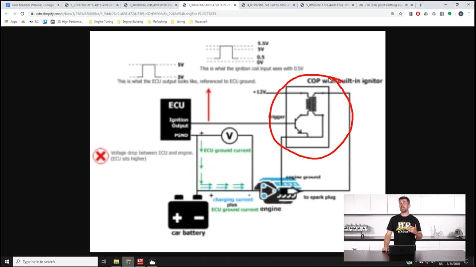
| 14:16 | The third aspect that we're going to have a look at here is what happens with our ignition system. |
| 14:25 | So in this case we're looking at a coil on plug ignition coil with a built in igniter module. |
| 14:32 | So what this does here is it takes an ignition output from the ECU to the trigger input on the coil. |
| 14:39 | So what it's looking for here is a square wave output from the ECU so that the coil knows when to trigger. |
| 14:47 | So a little bit hard to see here but this is what the ECU is outputting. |
| 14:51 | It's a square wave that runs between zero and five volts Now again here what happens at higher RPM we've got, I should also mention in this case the ECU has been grounded only to the battery negative, actually it hasn't been run to the engine block. |
| 15:12 | So this is the other way I know people do install ECUs. |
| 15:16 | So we've got our ECU ground current coming down through here at higher RPM. |
| 15:20 | Also at higher RPM we're going to end up with a charging current from our alternator and that obviously requires current flow as well so that's going through to our ECU. |
| 15:31 | So what happens here is that at high RPM, we're going to end up with a voltage drop across this power ground. |
| 15:42 | So what this does is it artificially ends up increasing the voltage at the power ground terminal on the ECU. |
| 15:48 | So instead of being a true zero volt, we're going to end up with a situation where maybe the output to the coil might float up to half a volt or thereabouts. |
| 15:59 | Now the coil itself is grounded to the engine block so what we end up with now is a situation where the output from the ECU here, the ignition output, instead of being at zero volts when the ECU isn't trying to trigger the coil, this might be half a volt or more depending on exactly what that voltage drop is. |
| 16:21 | So that gives a situation here which what we've got here, the square wave ends up offset. |
| 16:27 | So instead of going between zero volts and five volts in a square wave form, it might end up being 0.5 volts to 5.5 volts as far as the ignition coil is concerned. |
| 16:36 | Now that may or may not be a problem. |
| 16:39 | The issue is that with some coils, they will only require a relatively low voltage threshold to trigger. |
| 16:46 | So if that voltage drop is sufficient to get above that trigger level, what we can end up with is the coil erratically firing and it's not going to be synchronised at all to the engine position so we can end up with the coil firing absolutely anywhere in the engine cycle. |
| 17:04 | Again, really frustrating to track down, it's not immediately obvious why that's occurring and of course it can end up doing some damage, particularly if you've got a coil on a very high powered engine, running very high cylinder pressures, if it fires very very early in the engine cycle, essentially this is creating a same condition as pre ignition and that can do a huge amount of damage very quickly. |
| 17:30 | Alright so that's the situation we've got with our ground offsets and why we need to be very mindful of how we ground the ECU. |
| 17:39 | Now I've talked about a few issues there, you'll note that at this point I haven't really talked about solutions, don't worry, we will get onto that. |
| 17:46 | But before we do that, I want to talk about the next aspect which is magnetic field noise. |
| 17:51 | This is probably a lesser concern I think just given my own experience with what I've seen through our dyno cell doors. |
| 18:00 | However it is worth talking about while we're going through this. |
| 18:04 | And basically if we get everything right, we're going to kill two birds with one stone anyway. |
| 18:09 | So basically what we need to understand here is that when we have current flowing in a circuit we're going to end up creating a magnetic field. |
| 18:20 | Now the intensity of the strength of that magnetic field is going to depend on the size of the loop or the circuit and it's also going to depend on the amount of current flowing and this is really the same principle behind any of our ignition coils, we've got multiple windings of our coil in order to create a strong magnetic field and that's the principle behind the operation of an ignition coil. |
| 18:47 | Now what we're going to end up with however is if we've got a very large loop area, we're going to end up creating quite a large magnetic field. |
| 18:56 | So let's have a look at our next slide here and here we've got our ignition coil. |
| 19:02 | And in this instance we've got the coil, the coil has been grounded to the battery negative so that's our little connection here. |
| 19:12 | So basically what happens when the coil fires is that we have our high voltage output that goes to our ignition lead and then down into our spark plug, transfers down through the spark plug, of course the spark jumps the gap, starts the combustion process, and most people don't really think about the other part of that circuit but it is actually a circuit. |
| 19:34 | The ground side of the spark plug, obviously the spark plug is screwed into the cylinder head so it actually grounds through the body of the spark plug so that's where the earth strap from the spark plug basically grounds. |
| 19:44 | So then the current flow basically is into the engine block and normally that'll then be back through the earth strap to the car chassis, once it's gone through the car chassis, it's going to go to another earth strap that comes back to our battery negative. |
| 20:00 | So what we can see there is it's a relatively large loop area. |
| 20:03 | So if it's wired up like this, if our coil is grounded to our battery negative, we're creating the potential for producing a large amount of magnetic, or large magnetic field which can end up creating problems with triggering issues down the track. |
| 20:22 | So what we want to do to avoid that is instead of grounding the coil to the battery negative, what we can see is that our coil here is grounded straight to, well let's try and draw that properly, straight to the engine block. |
| 20:36 | So we've got our coil sitting on our cylinder head, we're going to generally have a common earth if we've got a multi coil system, we're going to have a common earth that connects to all of those coils. |
| 20:48 | You'll generally find that that will then be earthed straight to the cylinder head. |
| 20:52 | So as you can see in comparison to our previous example here, where we've got this large loop area, when we've got the coils grounded straight to the cylinder head, it produces a much smaller loop area. |
| 21:06 | We're not going to be in danger of creating those large magnetic fields and that gets us away from problems with interference, particularly with triggering errors at high RPM. |
| 21:19 | Alright so we're going to move into some questions shortly so if you've got any questions, this is a great time to ask them. |
| 21:27 | Before we move into the questions though, we're going to talk about the solution. |
| 21:31 | So what are we supposed to do here, how do we avoid this? Well what we're going to do is use what we refer to as star earthing. |
| 21:40 | And it's just a simple way of basically explaining that we're going to earth everything to one common point. |
| 21:47 | And this avoids the issues that we've just talked about with ground offsets, obviously if we're careful with our ignition coil wiring as well, we're going to avoid the problem with magnetic field generation. |
| 22:00 | So what we're going to do with our power grounds for our ECU, we're going to run these directly to a single point, we're also going to run our battery negative ground straps to the same point. |
| 22:13 | Now this avoids any potential problems as well if one of our ground straps is a little bit maybe second hand, not working as well as it should, let's say our ground strap falls off the engine, we're not going to get into that issue where the starter motor will back feed and use the power ground through the ECU as a way of still completing the circuit so you're not going to do any damage to your ECU. |
| 22:36 | In that instance you're going to know something's wrong because the engine simply won't crank, it won't start and you have to get stuck in and find out why that's the case. |
| 22:46 | Always easier than actually replacing your ECU. |
| 22:50 | So the next obvious question is where should our star earthing point be, what should we be doing, should it be at the battery negative, should it be on the chassis, should it be on the engine block? And this is again a question that a lot of people ask. |
| 23:07 | The reality is if we work through the process, work through what we've just learned, it actually becomes pretty obvious. |
| 23:14 | Now the first clue here is that we've already talked about the fact that our ignition coils are going to be earthed on the engine block or probably more accurately the cylinder heads. |
| 23:26 | I'll just mention here that when I talk about earthing to the engine block or the cylinder heads, I don't really care where that is. |
| 23:31 | Basically the engine is one big lump of metal with essentially incredibly low impedance. |
| 23:37 | So we can essentially earth to any point on the engine block or the cylinder heads, we're not likely to have any trouble with ground offsets being caused by that. |
| 23:46 | So basically at that point you can choose a convenient location on the engine block or the cylinder head, it doesn't really matter, it's not that critical. |
| 23:54 | The other aspect as we've mentioned, the fact that most sensors are going to be not conductive or not grounded I should say, through the body of the sensor back to the engine block so our MAP sensors, our fuel pressure sensors et cetera, those all run a separate signal ground wire as we've already discussed with the Mazda Miata example. |
| 24:18 | Now that's pretty typical. |
| 24:19 | We will find there are some sensors, some older knock sensors for example, that are only single wire, they're actually grounded through the sensor body. |
| 24:26 | The other one is some of the Nissan cam angle sensors are grounded through the body of the sensor back to the engine block. |
| 24:34 | So there's a clue in there as well, straight away if that's the situation then the engine block becomes our ground reference. |
| 24:41 | We've really got no way of doing anything about that. |
| 24:43 | So if that's the case, it would make sense there for you to use the engine block or cylinder head as our star ground point. |
| 24:50 | So key points there, what we're going to do is we're going to run our power ground or power grounds from our ECU directly to the engine block or cylinder head. |
| 24:59 | I know that a lot of people are tempted to, if you've got two or maybe three power grounds to run these together in a single wire. |
| 25:08 | It is better to run these independently. |
| 25:11 | This is going to make sure that you've got sufficient wire gauge to support the current flow that the ECU is designed to support. |
| 25:19 | It may not be an issue in every case but it's not really going to take you a lot more time or a lot more effort to run independent grounds to that same point. |
| 25:27 | Second point, our sensor grounds, hopefully you've figured out at this stage that you don't want to ground your sensors to the engine block, you want to use the sensor ground pins on the ECU and run the zero volt reference straight back to the ECU there, does not want to go to ground. |
| 25:46 | Then we've got our chassis ground or our battery negative. |
| 25:50 | Now this is another question I quite often get asked, do we need to run a negative or ground strap all the way from the battery negative to the engine block? Now in the perfect world that's what we would do, particularly if the engine is mounted, sorry if the battery is mounted in the engine bay, really there's no reason not to do that. |
| 26:11 | It's going to be a relatively short run for our ground strap. |
| 26:14 | However it is quite common practice for weight distribution and to clean out the engine bay, in a racecar to relocate the battery maybe into the passenger compartment or maybe into the boot of the vehicle. |
| 26:26 | In which case if you want to run a ground strap all the way to the engine block, yes you can do that but it's going to be incredibly long. |
| 26:34 | In these situations as long as you're using a clean grounding point on the chassis, making sure that you've removed any paint or rust or anything so it's got a good clean contact to the chassis, then we can use the chassis there so basically run an earth strap from the battery negative to the chassis, wherever you've mounted the battery and then just like the engine block we can assume that essentially there is very low impedance throughout the chassis so we're not going to end up with any concerns with voltage drops as we then run a second ground strap from the chassis near the engine bay, or in the engine bay, up to the engine block. |
| 27:11 | So that's the strategy to go ahead and do that. |
| 27:16 | Right so just looking to see if we've got any questions. |
| 27:23 | Yeah we've got one that's just popped up from Dimitri who's asked, wideband controller and wideband analog output grounds, which are best, my AEM has one measly sensor ground but three chassis grounds. |
| 27:35 | Yeah this is a real problem Dimitri and in all honesty, I have yet to find a wideband controller that uses an analogue voltage output which has been completely immune from grounding problems. |
| 27:51 | So the general process here is that most controllers will have a heater circuit and that heater circuit is relatively high current and it really doesn't have any influence on the analogue voltage output that's important as far as the ECU's concerned. |
| 28:07 | So generally the controllers that offer multiple grounding, there'll be a power ground for that heater circuit, you can ground that to the chassis, you can ground it to the battery, it really doesn't matter as long as you've got a good clean ground. |
| 28:20 | The key point here is that most of these controllers will have a analogue output and a sensor zero volt or analogue zero volt and it's important to make sure that that analogue zero volt wire is wired up to a sensor ground at your ECU. |
| 28:35 | So what this does is it should put the reference plane, the zero volt reference from the controller, will be the same as the zero volt reference on the ECU. |
| 28:45 | If you don't do that, you're going to have a lot of trouble with inaccuracies in your calibration but even doing this I've found that most of the analogue voltage based wideband controllers still have some discrepancy. |
| 28:58 | A little trick that I use here is with most of the controllers you can set them up to output a fixed voltage. |
| 29:06 | So what I do is basically set the controller to output a fixed 0.5 volt irrespective of air/fuel ratio and then actually set the ECU up and look and see what the voltage the ECU is receiving is. |
| 29:18 | Obviously it should be 0.5 volts, quite often you'll be surprised to see how far away it is. |
| 29:23 | Do exactly the same at 4.5 volts and that will show you what your voltage offset is. |
| 29:28 | You can then account for this with your calibration and you should get an accurate calibration that way. |
| 29:37 | Beau has asked, ground to the chassis, as long as there are enough welds to the panel, sheet metal, to run along, or run another long ground wire. |
| 29:46 | So I think I probably just covered that. |
| 29:48 | Basically yeah you can consider the chassis as a suitable ground reference, it's not an issue there and you don't have to run a separate ground strap the whole way forward from the battery. |
| 30:05 | Looks like we might have one more. |
| 30:09 | Ah so probably a little bit off topic here from OMEPeace who's asked, how can you wire an EGT probe to trigger a warning light without using a gauge? You'd need something in there to do that, the EGT probe itself produces a very very low voltage so it's pretty well useless without a thermocouple amplifier which generally will convert the output of the thermocouple, the EGT sensor, to a 0-5 volt output. |
| 30:37 | The only thing I can think of at the moment off the top of my head is you'd need to input that into either an ECU or a dash and then set up a table to trigger a warning light as an output once that goes above a point that you're uncomfortable with. |
| 30:53 | NickShop has asked, I'm relocating the battery in my R32 GT-R, I plan on running a negative cable to the engine, is it still acceptable to ground the fuel pump to the battery? Yes, absolutely, so I'll actually talk about this because this is another area I have seen a few issues, particularly with factory wiring, Subaru is one of the vehicles that I've seen this quite a lot. |
| 31:16 | Is where we use the factory wiring for the fuel pump, obviously absolutely 100% fine for a stock application but once we start pushing the engine a little bit further, particularly if we've fitted a larger fuel pump, you can find out that even with a larger fuel pump, you're actually running out of fuel and interestingly if you check the voltage across the fuel pump, instead of the 13.8-14.2 volts we'd expect with the engine running, the alternator charging, we may find that we're only getting down to maybe 12.5, maybe 12 volts. |
| 31:47 | And while obviously you'd think well fine it's not getting a good enough power feed, yes that can be a problem. |
| 31:54 | In some applications, it's actually the poor grounding through the factory wiring harness that's the issue so sometimes just replacing that ground straight to the, you can run to the battery negative or even the chassis, again using the chassis as your ground plane, that works pretty well for batteries. |
| 32:16 | Nissan John has asked, can you run most ECU signal wires in a twisted pair to reduce electromagnetic radiation? OK so the reality, and again this is a question we get quite often, the reality is that for most of the signals, most of the sensors that we have hooked up to our ECU, EMI, electromagnetic interference really isn't actually as big a concern as you'd think. |
| 32:38 | Obviously we want to take the precautions that we've already talked about in terms of generating magnetic fields with the coils et cetera, to make sure that we aren't generating undue electromagnetic interference. |
| 32:49 | Obviously the same thing goes for using solid ignition leads or maybe non resistor style spark plugs. |
| 32:56 | So there are some common sense aspects that we still need to tick off here. |
| 32:59 | But really the signals that are most sensitive to electromagnetic interference are really our engine speed inputs. |
| 33:06 | This is why those wires are run in a shielded cable. |
| 33:10 | Generally there's no need to shield or twist together any of our other signal wires. |
| 33:24 | Brian Sexsmith has asked, do you share the sensor ground with a datalogger ECU and dash? The answer there is going to depend on exactly what your products look like, what they're doing, how they're getting their information. |
| 33:43 | So basically if you've got a standalone datalogger that's taking information from the ECU via maybe a serial or a CAN interface, then that doesn't actually, the ground offset's actually not going to have any affect. |
| 33:59 | The information is being sent from the ECU to the datalogger in a data stream, so it's not an analogue voltage that's prone to those ground offsets so that's not an issue. |
| 34:09 | Same with the dash there. |
| 34:12 | The issue that would come about, kind of an answer to the earlier question we had about wiring in an AEM wideband controller. |
| 34:21 | If you are sharing sensors between these different units, then it's important that the sensor zero volt is at the same plane, so in which case you'd want to make sure that your sensor grounds are all connected together. |
| 34:38 | Cars Bars & Guns has asked, any special best practices for grounding the shields of shielded cables? Not really, this is pretty straightforward, again just following the manufacturer's wiring diagrams. |
| 34:51 | The key point to understand here is that with a shielded cable, we only want to ground the shield at one end, that's going to be the ECU. |
| 35:00 | Generally the shield is going to be grounded to either internally inside the ECU or it'll run to a ground pin at the ECU that should be documented on your ECU wiring diagram as well so pretty straightforward there. |
| 35:15 | We don't want to end up grounding, or earthing that shield at both ends, that's the worst thing you could do. |
| 35:21 | I've had a couple of people ask, if you only ground one end of the shield, isn't that going to create an antennae. |
| 35:29 | Yeah to a degree that's exactly right but the aspect there is that the shield is doing its job of basically taking that electromagnetic interference and draining it to ground so it's protecting the conductors underneath from that electromagnetic interference. |
| 35:51 | Beau has asked, factory harness situation, upgrading coils, stock coils are failing as they absorb temperature, aftermarket coils tend to deal with heat better. |
| 35:58 | Any additional ground place or leave it? So this is going to really depend on the particular coil that you are using. |
| 36:06 | One of the ones that's become very very popular in the aftermarket, cost effective and incredibly powerful is the IGN-1A coils. |
| 36:14 | Those are quite a powerful coil but to get the best out of them, they do need a very good ground and generally you need to step up the wire gauge over what you'd use in a lot of factory coils. |
| 36:28 | So basically common sense there, making sure that you're following the wiring diagram for any aftermarket coils and following the manufacturer's recommendation. |
| 36:36 | Another issue that we will quite often see with a factory harness that is a little bit old is that it can end up suffering from degradation from heat and one that I know we see huge problems with in the Japanese market is a lot of the NIssan stuff, both the RB engines as well as the SR engines, where the coils sit underneath a cover, basically in between the cams and the basically the wiring as well as the coils get baked. |
| 37:07 | So the problem with that is you'll notice that when you pull the connectors off the coils, they're very brittle, sometimes the plastic breaks, the wiring obviously suffers as well so in that instance if you've got questionable wiring and this is really aside from earthing or grounding issues, questionable wiring, it's a really good idea to start fresh and make your own harness. |
| 37:29 | Sometimes you can buy aftermarket replacement harnesses for these popular engines, that is a cost effective option there. |
| 37:38 | Right looks like that's all the questions we've got here. |
| 37:41 | I've got a couple of questions a little bit off topic. |
| 37:48 | John's asked, any plans to have more than one tuner meetup this year? Look John I think at this stage we're probably going to run another one at PRI. |
| 37:57 | We have a pretty tight schedule and it's a little bit difficult for us to make too many trips away. |
| 38:05 | Obviously the U.S. or Australia are our two biggest markets, that's the best place to have meetups. |
| 38:09 | So at this point I would say PRI is looking like our most likely but we'll make more announcements as we get closer to that date. |
| 38:18 | Mustang James has also asked, any good aftermarket ECU recommendations, I have a '98 Mustang Cobra. |
| 38:25 | What I'll mention here is it's very difficult for me to make ECU recommendations. |
| 38:29 | The reality is with a 1998 Ford Mustang, it's not a particularly advanced engine, there's nothing particularly tricky going on there. |
| 38:40 | So you'll basically going be able to run that engine on just about any popular aftermarket standalone ECU. |
| 38:47 | The recommendations I always make in this situation is first of all, figure out what your budget is, what you're prepared to spend. |
| 38:53 | That's going to narrow down your available options. |
| 38:55 | Inside of those options then I would be looking for an ECU that is supported well in your particular country or your particular area. |
| 39:04 | There's no point buying a really competent ECU from the other side of the world that's going to do everything you want but you're going to have to wait overnight for any customer support if you've got questions about how that works. |
| 39:16 | So yeah if you're following our HPA courses though, I'd also recommend obviously if you're dealing with an ECU that we cover, which is Haltech, AEM Infinity, Link, Syvecs, Megasquirt, any of those ECUs, it's going to make your life easier because we've already got course content on them. |
| 39:35 | Alright we'll leave it at that, thanks for joining us everyone and we hope to see you again next week. |
| 39:41 | And of course if you've got questions that crop up after this webinar has aired, please ask them in the forum and I'll be happy to answer them there, thanks. |


