244 | Introduction to ECUMaster
Summary
In this webinar we’ll cover an introductory look at the ECU Master Black ECU and the features it offers. For this webinar we’ll be using a V11 Subaru STi incorporating daw throttle and variable cam control.
| 00:00 | - Hey team, it's Andre from High Performance Academy, welcome along to another one of our webinars and this time we're going to be diving into an introductory look at the Ecumaster EMU Black ECU. |
| 00:12 | This is an ECU that we've been promising to bring you some content for some time and we finally got the opportunity to get it up and running on our version 11 Subaru STi. |
| 00:22 | And this ECU is pretty much what you'd expect from most modern ECUs, it's got a lot of functionality in terms of the normal aspects you would expect, sequential fuel injection, direct coil on plug spark, also encompasses drive by wire throttle control which there are still some ECUs that aren't supporting. |
| 00:43 | It also has onboard wideband lambda control and it supports variable valve timing as well so pretty fully featured ECU. |
| 00:54 | What we liked about it is the really tiny packaging, it's very very small in its footprint and it's also really competitively priced, I won't mention a price because the fact is that the price is going to vary slightly depending on the market that you're purchasing it in. |
| 01:12 | However it does stack up really favourably against some of the other mainstream ECUs that we have on the market that compete with the same feature set. |
| 01:20 | Now the Ecumaster range have become pretty popular in Europe, also in the US. |
| 01:27 | We haven't seen them too much over here in New Zealand so it has been a bit of a learning curve for me in particular getting my head around the whole system. |
| 01:35 | The reason we have got this ECU installed in our Version 11 STi was to add some content to our Practical Standalone Tuning course. |
| 01:46 | I'm about 3/4 of the way through shooting that at the point that we are recording this webinar so depending when you are watching this webinar, if you're viewing it in the archive, it may already be added into our worked example library in there. |
| 01:58 | So if you do want to learn more in depth about how to use the ECU, that's going to be perfect for you. |
| 02:03 | As time goes by, we will be also adding some more specific webinars into our archive covering some of the intricacies of aspects such as the idle speed control, the variable valve timing control, boost control etc so that'll give you a more thorough understanding of those elements, also cold start enrichment, transient enrichment, those sorts of things. |
| 02:24 | So today we're going to be looking at a more sort of overall cursory view of the system, how it works and we'll give you a bit of a guide through the software. |
| 02:33 | Now I will mention that there are a couple of limitations that come with this ECU for our particular application. |
| 02:41 | Ones that we were 100% aware of when we purchased it. |
| 02:44 | In particular, probably the biggest one here is the variable valve timing control. |
| 02:49 | It is only designed with the ability to control two cams. |
| 02:53 | So if you are running an inline four cylinder, six cylinder etc, with two variable cams, it will be able to control independently the intake cam and the exhaust cam. |
| 03:05 | In our case this version 11 STi is a Japanese domestic market spec with the two litre EJ series engine running quad variable cam control. |
| 03:14 | So this presented a problem because we cannot control all four cams. |
| 03:19 | What we chose to do here was to use the variable cam control on the inlet cams only and leave the exhaust cams fixed. |
| 03:27 | Now that's perfect for us, we really aren't interested in so much the outright performance, we're more interested in just being able to develop our course material and it doesn't really matter if the exhaust cams are operational or not, I just mention that for those who are maybe viewing this and thinking of getting the Ecumaster up and running for their own Version 11 STi. |
| 03:46 | The other issue here is that for us, the Version 11 STi is, does utilise CAN messaging between the ECU and the other electronic modules on the car. |
| 03:57 | In particular the gauge cluster. |
| 04:00 | The Ecumaster ECU right now does not replicate the Subaru CAN message data stream so this is problematic because we don't get aspects such as the RPM or engine coolant temperature on the dash. |
| 04:15 | Also causes some problems with traction control and ABS systems so this is OK for our dyno use but would be problematic if you were intending this for use on a road car. |
| 04:28 | It's quite possible that in future Ecumaster will add the Subaru CAN data stream and I only mention that again just for those who maybe are going to come out of this webinar and think I'm going to go and put an Ecumaster EMU Black on my own Version 11 STi. |
| 04:42 | Probably right now not what I'd recommend. |
| 04:44 | Other aspect here is with this particular EJ series engine it runs the tumble generator valves or TGVs. |
| 04:53 | In factory form these are controlled with a position sensor so that the factory ECU can open and close them to a specific target. |
| 05:02 | Not a big deal in the aftermarket, most people will simply remove the tumble generator valves completely so we've gone with the option here of using a pulse width modulated output just to drive the tumble generator valves fully open all the time that the engine is running so we don't have factory like control over the TGVs. |
| 05:23 | Alright with a brief introduction out of the way there, let's just jump into our software and I think what we'll do is we'll walk through some of the features of it. |
| 05:32 | We'll do a little bit of steady state tuning and as long as we don't run out of fuel, which is marginal right now, I'm sorry to say, we'll see if we can squeeze in a ramp run there and have a look at some of the functionality around that as well. |
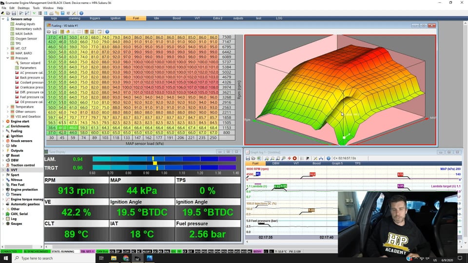
| 05:45 | So the user, the software is relatively user friendly, it didn't really take me very long to get myself pretty familiar with the layout and the way this sort of works is we've got a range of different tabs up the top here so we can see at the moment we're on our fuel tab. |
| 06:02 | Now you can configure these tabs as you like, we can see for example we've got one labelled as extra 2 right now which has got nothing on it, if I was to cycle through here we can see that each of these tabs is sort of set up for different functionality and different tuning. |
| 06:16 | So again you can completely customise these to your liking with whatever combination of parameters, tables, displays, logging on those tabs that you want. |
| 06:27 | So for example here we've got our fuel tab set up with our volumetric efficiency table here. |
| 06:33 | I've got a graph log set up over on the right hand side which is, I've found, quite powerful inside of the Ecumaster software. |
| 06:41 | It gives you a fully featured log file and you can pause and play that back. |
| 06:47 | What it does, obviously I'm just sitting here idling at the moment, there's not a lot to see but by scrolling through here we can see first of all exactly where abouts we were operating in any of the tables and you can see what the relevant outputs were at the time. |
| 07:01 | We'll just start that up for the moment. |
| 07:03 | So you can just reposition all of this data as you wish. |
| 07:08 | For example here when we are viewing our fuel and ignition tables it can be beneficial to view these graphically. |
| 07:15 | It's a little difficult sometimes to really spot trends in a table if we are just viewing them numerically like this. |
| 07:23 | So you've got the option in the toolbar here to display the data in a number of ways. |
| 07:26 | We can just view it completely graphically, we can view it numerically as we were or you can split the view so you've got both the numeric and graphical views which is one of my preferences here so we can see the general shape to our VE table and we can pull it around and reposition it to suit whatever we want to see. |
| 07:46 | So pretty user friendly there, we've also got some basic parameters down here in our tune display which gives us some of the information that we may be wanting to view. |
| 07:56 | In particular here, one of the key features when we are doing our fuel tuning, we've got our measured air/fuel ratio and we've got our target air/fuel ratio. |
| 08:05 | I'll go over a little bit about how we're getting the air/fuel ratio data into the Ecumaster in a moment. |
| 08:12 | We've also got obviously you can see manifold pressure, we've got RPM throttle position, our volumetric efficiency etc. |
| 08:19 | And again you can choose which of these parameters that you want to display. |
| 08:23 | Now what I'll do is just quickly go through some of the setup functionalities here. |
| 08:30 | So that you can sort of see how that works. |
| 08:33 | And we've got the menu structure down here on the left hand side which is how you can access all of that functionality. |
| 08:41 | We'll close that down for a moment and we can see all of those options. |
| 08:44 | So I just want to sort of take you through a bit of a basic workflow as to how we would set this ECU up. |
| 08:51 | And I think what we'll do is we'll start with our throttle position, actually we'll start with our oxygen sensor, I've just mentioned that so we can double click on any of these parameters and it will add it into our current tab so I'll just bring this up over the top of our VE table at the moment. |
| 09:06 | So this ECU does have a built in wideband controller. |
| 09:11 | We actually had a lot of trouble with this and at the moment Ecumaster haven't been able to come to the conclusion as to what was wrong there. |
| 09:21 | It's relatively straightforward, we've got the ability to run either an LSU 4.2 or 4.9 sensor wired directly up to the EMU Black but as I say we had trouble, we couldn't actually get a valid reading from a 4.9 lambda sensor. |
| 09:37 | We went backwards and forwards with Ecumaster over in Poland which I found to be, Jacob in particular, exceptional to work with, he's been very quick to reply to any of the questions we've got. |
| 09:48 | To the point where because he couldn't get a resolution to our issue right there and then, we already had a Haltech wideband controller in the car for the Haltech ECU we run on so he simply wrote some new code and a new firmware version was released which gives us ability to use the Haltech WB2. |
| 10:07 | So that's our sensor type here. |
| 10:09 | Looking into it further, seems like we're on our own here so it might be a hardware fault with the ECU that we've got, doesn't seem like I can find anyone else complaining about the use of the onboard lambda and that's a really nice feature as well because it saves you a bit of expense being able to use an onboard lambda controller, you don't need to go and buy an external controller. |
| 10:32 | The other thing is that the way the Ecumaster does this is it does use the calibration resistor inside the wideband sensor whereas a lot of ECUs will require a free air calibration which does work to a point but it gives you one reference data point, it gives the controlller one reference data point whereas using that calibration resistor does do a more accurate job so it's my preference where possible. |
| 10:56 | Anyway, we can see that you've got the ability to bring in a narrowband, LSU 4.2, 4.9, use an external controller, obviously the Ecumaster lambda to CAN and then we've got our Haltech lambda controller. |
| 11:08 | We can also select the fuel that we're running on, the mix of fuel based on being able to display an accurate air/fuel ratio so this is just adjusting the stoichiometric air/fuel ratio for the particular sensor fuel that we are using. |
| 11:24 | Then in this case you can also have a second lambda sensor but we obviously don't need that with our single exhaust system. |
| 11:32 | So that's our lambda sensor setup. |
| 11:34 | Now moving down I'll just show you through a few of these, the next one that we'll quickly look at here is our throttle position sensor. |
| 11:40 | Now this is obviously a little bit unique here because we are running a drive by wire system, so this uses a driver accelerator pedal position or APP as it's normally described and then we've got throttle position at the actual throttle body. |
| 11:55 | So this one here is for our accelerator pedal and this will work regardless whether it's drive by wire or it is a conventional cable throttle. |
| 12:05 | Now interestingly here the setup for this, we've got the TPS minimum voltage and maximum voltage which I've just circled there. |
| 12:12 | So it's a normal analog voltage input to the ECU, zero to five volts. |
| 12:16 | There isn't actually a calibration feature for this and instead you are going to use the graph. |
| 12:23 | So not a big deal but I found it was a little bit unusual. |
| 12:25 | So if we come over here, we've got a graph set up already for TPS and what we're looking at here in brown is our TPS voltage. |
| 12:34 | So obviously right now I'm off the throttle so we can see our closed pedal voltage is 0.67 volts. |
| 12:41 | Of course corresponds nicely to our minimum voltage. |
| 12:44 | So if I just give the throttle a quick blip to full throttle, and we'll just let that cycle through for a second and stop that. |
| 12:53 | So we can pause and start the logging any time we like. |
| 12:55 | We can see our voltage, actually I must have pressed the pedal a little bit harder, we're at about 3.99 volts, call it 4.0 volts so we can just enter that into this particular point here. |
| 13:07 | Also important to mention with the Ecumaster EMU Black, when we make a change like this, we need to actually write that change to the ECU to make it permanent. |
| 13:19 | So if you just disconnect from the ECU at this point and then power it back up, that change will not remain active. |
| 13:28 | It will actually guide you on this, when you connect to an ECU if you haven't stored the change, it will tell you that the data between the ECU and the software actually is different and it will ask you which one you want to use. |
| 13:41 | However once we've made a change and we're comfortable with that, we can just use the little make permanent, make changes permanent icon up here in the tool bar and that will write them to the ECU permanently. |
| 13:55 | Alright so we had a quick look at our TPS, now on the same note there the rest of the calibration for our drive by wire needs to be done as well. |
| 14:03 | And this is something that actually changed once we got this ECU. |
| 14:07 | So depending on what firmware version you are on, you may want to update the firmware, if we go to the tools drop down menu, you can see that there is now a drive by wire calibration too. |
| 14:18 | I'm not going to go through this, it's very straightforward but it does take a little bit of time and essentially what you want to do is have the ECU powered up but the engine not running and then you can just go through and click start and it'll run through the calibration process. |
| 14:33 | So not only does this automatically calibrate the throttle position minimum and maximum voltages, which otherwise you need to do using the logger and manually opening and closing the throttle butterfly. |
| 14:45 | It's also going to actually develop the PID algorithm gains for the drive by wire control. |
| 14:51 | So I believe this was on version 2.118 and above so if you are on older firmware, then it would be in your best interest there to update that. |
| 15:04 | Coming down we've got our intake air temperature and our coolant temperature as well so we'll just go through and have a quick look at those. |
| 15:13 | You can expand that out. |
| 15:15 | Now for our intake air temperature and our coolant temperature, it's easiest to use the sensor wizard, I'll bring that up, and you can see that you can choose from a range of different pre setup calibrations from this drop down menu so provided you've got a sensor that's pretty conventional, that's going to be the typical way that you'll be able to do that. |
| 15:38 | Always a good idea as well, this is just a tip that I have when you are setting up the calibrations for the likes of intake air temperature and coolant temperature, just as a bit of a sanity check, when the engine hasn't been started, you just want to have a look at your coolant temperature and your intake air temperature and we've got those side by side down here, and generally they should be, understandably the same as your ambient temperature and generally within at least sort of one or two degrees of each other so that's always a good sanity check just to make sure that the calibration you've selected makes sense and the numbers that you are getting are sensible there. |
| 16:16 | Coming down to our MAP and baro so this actually has an onboard MAP sensor. |
| 16:21 | So no reason to necessarily use an external unless you're planning on running beyond the capabilities of that internal sensor. |
| 16:29 | If we bring up our parameters here you can also select to use an offset if you want to offset the manifold pressure value, you can also set up how you're going to use a baro sensor if at all. |
| 16:44 | So at the moment we've got that set to do not use so we're not using baro correction. |
| 16:48 | If you are using an external MAP sensor that you've wired up, you can choose to use the internal MAP sensor on board the ECU as your baro or of course you can add in an external barometric pressure sensor. |
| 16:59 | Here we're not really seeing massive variations in altitude so barometric pressure correction for me personally, not that important. |
| 17:08 | Alright we'll also quickly cover off our pressure sensors here. |
| 17:13 | We actually have added a fuel pressure sensor to this which is being displayed down here in our tune display. |
| 17:20 | And you can come down to fuel pressure calibration, open that up and you can manually enter the data for this if you wish. |
| 17:28 | This is a pretty typical sensor, this is a Honeywell 0-150 psi fluid pressure sensor with two set point there, 0.5 volts and 4.5 volts, this calibration is in bar. |
| 17:42 | Alternatively you can use the parameters here and you can, no sorry that's not what I wanted to do, the sensor was what I wanted to show you. |
| 17:51 | And you can choose a calibration from this drop down menu, pretty much exactly like what we saw already and you can assign this to whatever your sensor is, so in this case, we would obviously choose fuel pressure but I'm not going to change that. |
| 18:07 | So that gets most of our set ups done and out of the way. |
| 18:12 | Of course there are also outputs to consider here, if we come down to our outputs, we'll have a quick look at those. |
| 18:21 | In this case let's quickly have a look at our fuel pump. |
| 18:25 | So we can open that up and our fuel pump is set up, we can define which auxiliary output the fuel pump is on, obviously auxiliary four here. |
| 18:34 | Now the other feature we've got here is we've got this little box to invert the output so this is going to depend on the way your relay or the control for your output is wired, whether the relay needs to go high or low in order to switch. |
| 18:49 | A nice feature with this is by clicking that little box, it will essentially run that output so you can actually test using this feature to see whether your outputs are operating correctly. |
| 19:01 | We've also got another tab assigned here called outputs which goes over the wider range of outputs there so for example we've got the coolant fan, we've got exactly the same ability to invert that output which is the one I've got ticked there, that will of course run the fan. |
| 19:19 | Another way that we can test our outputs, we can come to the little green tick box for test outputs in the toolbar, I can't do this with it running as it's just warned me but essentially what that's going to do is open up another little menu structure and allows you to test for example your ignition outputs and your injector outputs and it will allow you to pulse them a certain number of times. |
| 19:43 | And this is a really good thing to go through during your initial setup. |
| 19:48 | It allows you to confirm first of all that the outputs are actually functioning and particularly with your injectors and your ignition coils it will allow you to go around and you can audibly test to figure out where the injector is located on the engine and make sure that you've got the wiring correct and the correct cylinder ignition and fuel is actually operating. |
| 20:11 | Right we'll have a quick look at some of the tuning operations here as well. |
| 20:15 | So we'll just get our fan up and running here, now I should have mentioned at the start, we will be having questions and answers at the end of this lesson so if there's anything that I talk about that you'd maybe like me to dive into in a bit more detail, then please ask those questions in the chat. |
| 20:32 | So for this we'll come back across to our fuel logging tab and click on that. |
| 20:38 | So I've just got this set up with some of the key parameters that I'm interested in looking at here. |
| 20:44 | So at the top set of graphs, in red here we've got our engine RPM, in blue on the other side we've got our manifold pressure. |
| 20:51 | Then we've got our air/fuel ratio. |
| 20:53 | So in this case being displayed in terms of lambda. |
| 20:56 | In green we've got our measured lambda and on the right we've got our target lambda value. |
| 21:02 | So this is a VE based ECU, I'll deal with that in a second in a bit more detail. |
| 21:06 | Also got our injector duty cycle. |
| 21:09 | At the moment we've got our idle ignition correction showing that that's operational as well. |
| 21:14 | We'll talk about our idle tuning shortly and then I'm also displaying fuel pressure here as well so again you can choose to display whatever you want on here. |
| 21:23 | If we right click, you can set the particular channel for that graph or you can also change your preset, so you'll see here there are some preset channel configurations which are already designed for certain features that you are wanting to look at. |
| 21:40 | So what we'll do is we'll get ourselves up and running here and do a little bit of steady state tuning and we'll talk about some of the options when it comes to tuning. |
| 21:52 | Let's just get back into steady state control, we'll just come up to about 3000 RPM here. |
| 21:58 | So if we come across to our fuel table, we can see we've got a red cross hairs that shows us where abouts we're operating in that table so just like any ECU, understandably we want to make sure that we are as close to the centre of a particular cell as we can get before we choose to make any adjustments. |
| 22:20 | So we can see that we're currently sitting at 89 kPa, 2900 RPM give or take a little bit and we can see straight away from our measured air/fuel ratio that we are a little bit lean so we've got a few ways of making adjustments to the numbers in the table here. |
| 22:38 | So the first one is that we can use our plus and minus keys on our keyboard to add or subtract 1% so particularly if you're already pretty close to the target, a quick and easy way to make your changes and you can see we're straight away onto our target air/fuel ratio. |
| 22:54 | If you want to make a larger change than that, if we hold down the shift key and press plus, that'll make a 5% change so every time we press the plus key we're going to make a 5% change, likewise shift and minus key's going to make a minus 5% change. |
| 23:11 | If we want to start getting really fussy though if we hold down the alt key and then press plus, that's going to make a 0.1% change every time we press it and of course alt and minus will make a 0.1% change in the opposite direction. |
| 23:24 | We'll have a quick look outside of the area that I'm actually tuning at the moment. |
| 23:28 | So if we highlight a few cells here, there are a few other options that are available. |
| 23:33 | So let's say we want to add five to that whole set of cells, so what we can do is just enter the value five and then out mathematical function, in this case plus, press enter and that will add five. |
| 23:47 | Likewise, if you want to undo a change that you've made, control Z will undo that. |
| 23:53 | That's a function that a lot of ECUs don't have, I'm not really too sure why. |
| 23:58 | Super helpful when you are tuning if you make a mistake so control Z, something to keep in mind. |
| 24:06 | The other functions that are useful are where you want to make arithmetic changes like a percentage change, so let's say we want to add 5% to all of the cells that I've got highlighted there, so we can enter 1.05, our multiplication symbol there and press enter, that makes that change. |
| 24:24 | Now you can see that all of those cells that I've changed at this point have that little yellow triangle on the bottom right hand corner and this is just to demonstrate that those changes have not been made permanent yet so again we'd need to write the changes to the ECU, we can see that one cell that we did change there, 79% VE, that's showing that little triangle so if I just press the make changes permanent, that's now written to the ECU. |
| 24:55 | Right so there's a few more things to think about with this table as well, with our fuel tuning so we've obviously got our brake points here, we've got RPM on the vertical axis here, our Y axis and we've got MAP, manifold pressure on the horizontal axis. |
| 25:09 | So a couple of ways we can configure the break points or bins for those axes. |
| 25:14 | If we come down here and right click, you can see we've got the option for our X axis bins wizard, so we'll click on that. |
| 25:22 | And essentially what you can do here is just define the minimum load value, the maximum load value and then what sort of interpolation you want between them. |
| 25:29 | In linear we can go exponential, generally for this sort of table, linear is what we'd want there and click OK and that's basically going to automatically span your axis as required. |
| 25:41 | The other option here, and you could do of course exactly the same with the vertical axis, the other option here, because this kind of gives us a bit of a weird set of break points and I'm kind of a bit fussy with the way I want my tables set up so I don't necessarily want a break point here at 1153 RPM. |
| 26:01 | That doesn't really work with my mind, not that there's anything necessarily wrong with it so let's have a look here. |
| 26:07 | If we double click on that we can enter a break point, press enter and what that will do as well is interpolate the values so we don't actually need to retune that 1000 RPM row there, we can see that all of the numbers in that 1000 RPM row now have that little yellow arrow, they've all changed and that's because we've changed our break point. |
| 26:28 | So you can go through, set those break points up however you want. |
| 26:32 | Those changes as well, if we head across to our ignition table, will be applied straight away to the break points for our ignition table. |
| 26:40 | Generally but not always, we do want the break points to be the same between our ignition and our fuel tables. |
| 26:48 | Now I did mention that essentially this ECU does work on the volumetric efficiency principle so we do also have a air/fuel ratio table so we want to set our lambda target table while we're going through this. |
| 27:03 | So we come down to our fuelling and we can see if we come down to our fuel tables here, if we expand on that, we've got two VE tables, VE table one and two. |
| 27:14 | We're not running dual tables at the moment so we're always on VE table one and we've also got our lambda target one table. |
| 27:21 | So let's just open our lambda target table up and we'll expand that out a little bit so we can see what that involves. |
| 27:27 | Exactly the same, little bit coarser in terms of the break points or bins for this table and of course it's not really essential to have such tight break points with our lambda target table, we don't generally tend to change our lambda target too much. |
| 27:42 | So the idea here, the workflow with this is very much like any volumetric efficiency based fuel model, what we want to do is start by setting. our fuel targets to the actual air/fuel ratio targets that we intend to run and then the process is to tune our VE table until our air/fuel ratio actually matches that target. |
| 28:03 | The benefit then is that provided we don't make mechanical changes to the engine that could affect the volumetric efficiency, if we do decide that we want to change our air/fuel ratio, see perhaps if the engine responds better by running a little bit richer at wide open throttle then we just come through and make our tuning changes directly in our air/fuel ratio target table and if everything's tuned correctly, calibrated correctly then that should in fact give us our desired result. |
| 28:32 | Now there is a little bit more to understand with this as well because with our VE table it is important, or VE based fuel model, it is important to give the ECU a few more parameters to work with so if we open up our fuelling general tab here, for example we've got our engine displacement, that needs to be set up correctly, as well as our injector size. |
| 28:57 | So if we have either of those set up incorrectly then we're going to end up with problems long term. |
| 29:04 | Now while I've got that general fuelling parameter set up there, we can also see we've got our fuelling type, so we're set to speed density here and if we click on our drop down menu, we've got the option of a variety of different alpha-N styles, either with or without MAP based multiplication. |
| 29:20 | The one that we've got down the bottom here, alpha-N with MAP multiplication as well as MAP based ignition, this would be what we would typically choose if we're running a turbocharged engine with individual throttle bodies so speed density, that's going to be what will work for the majority of applications. |
| 29:38 | Now at the same time here let's just come down and have a look at our injector setup and we'll open that up and we've got our injector wizard, so again, double click on that, we can choose our injectors from a dropdown list assuming that yours are supported. |
| 29:54 | It's a fairly extensive list and that's going to do all of the heavy lifting for us. |
| 29:59 | Alternatively you can set these up manually, essentially here under injectors cal, if we just open that up and bring it up and enlarge it slightly, this is our injector dead time or battery offset etc so pretty easy with this system to define your injectors or characterise your injectors yourself. |
| 30:18 | Doesn't get too detailed with the likes of short pulse width adders or high slope and low slope so you don't need particularly detailed information about your injectors in order to set that up. |
| 30:30 | Right so we've looked at our fuelling now, let's just head across to our ignition and we'll have a quick look at that. |
| 30:38 | Pretty much nothing too out of the ordinary here, just like tuning the ignition timing on any aftermarket ECU so we've got our ignition table there. |
| 30:48 | Again, we can choose to display that graphically as well as numerically and we'll just close that back down there. |
| 30:57 | One of the things with any aftermarket ECU though is setting your base ignition timing is very critical so we can do that, we'll head back across to our triggers tab here. |
| 31:08 | So this gives us the ability to define the trigger setups, in this case we've got three trigger inputs, we've got our primary trigger here which is essentially our crankshaft speed sensor, then we've got our secondary trigger which is what I prefer to call a synchronisation input, so CAN position and then in this case we've got a cam two position as well which is cam position for the other bank inlet cam. |
| 31:34 | So if you're running a conventional non VVT engine, you're not going to have that cam input two. |
| 31:41 | Here we can define our sensor type so here we can see we're running a VR sensor, a variable reluctance sensor on the crank for our primary trigger and hall/optical for both our cam one and cam two. |
| 31:55 | There are a few other parameters here which I won't dive into right now, that get a little bit more advanced than our introduction. |
| 32:02 | Important aspect here though is our trigger type, we want to obviously make sure that the ECU can correctly decode the crank signal and the cam signals coming into it so here we're running the pretty standard 36 minus 2 minus 2 minus 2 Subaru pattern and also our trigger edge is quite critical here, particularly with a variable reluctance sensor if we're choosing the wrong edge of our sensor to trigger off, we're going to end up with timing drift as the RPM increases. |
| 32:35 | Now actually setting the base ignition timing though, that can be done down here with our ignition angle lock. |
| 32:44 | So if we tick that little box here, that's going to then bring up the locked angle parameter which was previously hidden and what that does now is it sets our ignition timing to a fixed 10 degrees, irrespective of compensations and irrespective of what you've actually got in the tables, you're going to then connect a timing light to number one coil and physically check the timing that you're getting at the crankshaft making sure that it matches. |
| 33:09 | Now the way that we can adjust that as with these two parameters here, we've got first trigger tooth and then we've also got our trigger angle. |
| 33:18 | So essentially what we want to do is choose a combination of our first trigger tooth and our trigger angle so that first of all, our base timing is correct, we have in fact got 10° of ignition advance being delivered and we also want to make sure that our trigger angle is as least as great as the maximum advance value that we intend to use in our ignition table. |
| 33:40 | Now 69°, probably a little bit more advanced than we really need, typically I'd want to see that maybe around about 45, maybe 50° but what you're essentially going to be able to do is time the engine correctly with more than one combination of trigger, first trigger tooth and trigger angle but if you end up with a trigger angle that's only 25°, therefore that's the maximum advance you're going to be able to provide. |
| 34:05 | Pro tip here and this is one that's really easy to forget about, once you're finished, go and untick that box otherwise you're going to find your ignition timing will be fixed at 10° and you can end up chasing your tail, wasting a bunch of time on the dyno wondering why your timing isn't actually affecting the way the engine operates. |
| 34:23 | There is also a trigger scope function which I've got displayed down here, so this will basically give us a graphical view of the trigger inputs which we've got already there. |
| 34:37 | You can do this with the engine running or cranking, we'll just click on that again. |
| 34:40 | So it asks you to get a good idea of the relationship between the different trigger inputs. |
| 34:48 | Right we'll also have a quick look at our idle tuning so let's head across to our idle tab, again you can do this wherever you like, but I've got the key parameters that I want to look at set up here. |
| 35:02 | So first of all our idle parameters, we've got our idle valve type, and I'm not going to go through all of this but you can see that we're using drive by wire here. |
| 35:10 | You can use obviously a range of different options there, solenoids, steppers, etc but we're using drive by wire. |
| 35:17 | When we are using drive by wire, we need to also consider another parameter that comes from our drive by wire parameters box down here on the right hand side and the specific one that I'm interested in here is our idle range. |
| 35:31 | So in this case it's 10% so basically this defines the maximum throttle opening that will be used under idle conditions. |
| 35:40 | And that then becomes part of our idle reference table values here so essentially these numbers are a base setup for our idle position before closed loop control comes in. |
| 35:51 | So a value of 100% in this table plus our maximum idle range of 10% actual throttle opening. |
| 35:59 | So there's a bit of information in there, we want to make sure that our drive by wire parameters for our whole range is sufficiently high so that we can get our target idle speed when the engine is completely cold. |
| 36:09 | However if we make that too high, we're going to lose resolution in our idle reference table and essentially it's going to make it harder for us to get good control over the idle speed so being a little bit sensible there is the order of the day. |
| 36:23 | So this table, our idle reference table, our base duty cycle as I've mentioned before, or base duty cycle or base throttle opening, before any closed loop control comes in. |
| 36:35 | You can see we've got that set up as a three dimensional table, we've got our idle target RPM on the vertical axis and our coolant temperature on the horizontal axis and what we want to do is do a good job of getting this table set up so that those values are as close as we can get them so that the closed loop control has less work to do. |
| 36:55 | This all works in conjunction with our idle target table here so this is our desired idle speed, obviously two dimensional table relative to our engine coolant temperature. |
| 37:05 | And from 70°C and above I've set our idle target to 900 RPM. |
| 37:11 | So that we can see what's actually happening and how good our control is, we've got a set of parameters here so we've got our idle target, we can see that sitting at 900 RPM. |
| 37:24 | We've also got our PID control so in this case our idle PID duty cycle correction. |
| 37:31 | At the moment we're pulling 2% out so it's actually closing the throttle very slightly. |
| 37:36 | We can see our parameter here for our RPM showing what our actual RPM's doing. |
| 37:41 | So moving around a little bit but pretty close to our target. |
| 37:44 | The other correction here that we've got is our idle ignition correction so as with most modern aftermarket standalone ECUs we've got the ability to use idle ignition control to advance and retard the timing based on our idle error and that is being applied to our table here so as our idle speed drops we can advance the timing towards MBT. |
| 38:06 | The effect of this is it increases engine torque which picks up our idle speed, as we go above our idle target we can see that we retard the timing slightly and this has the effect of reducing engine torque and dropping our idle speed. |
| 38:20 | So the two work hand in hand in conjunction there. |
| 38:23 | So far again with my testing, all seems to work really well and again we will run a more detailed webinar on the specifics of the idle system tuning at a later point as well. |
| 38:36 | We'll quickly have a look at our variable valve timing as well so we'll head across to our VVT tab. |
| 38:42 | And we've got our parameters here for our cam one, so we've got a offset parameter, essentially we use this to zero our cam control so that it is reading the correct values or the right values depending on the movement of our cam. |
| 39:00 | Again if we bring up our logging and we come across to our VVT, we can see our cam angle and our targets, obviously at the moment we are sitting at idle so what we'll do is we'll just bring our RPM up a little bit here and we'll be able to see our cam position move. |
| 39:19 | Using of course PID control to make sure everything is tracking nicely, we'll just stop that for a second and we can see our parameters up here in purple are our cam one angle target and our measured cam one angle. |
| 39:34 | Then below that we've got in blue our cam two angle for our other bank of intake cam and our target so in this case because we are running two intake cams on a horizontally opposed engine, we've got the system set up to basically use the same cam target table for both of our cams. |
| 39:56 | We've got that table set up here obviously numerically and graphically, again we can move that around and view it. |
| 40:03 | Generally with our cam control, then idea with our intake cam is we're going to advance the cam at low RPM to improve our bottom end torque and turbo spool. |
| 40:12 | And then retard the cam at higher RPM so we can see that's exactly what's happening here, we're sitting at around about 35 to 40 degrees advance between 2500 and 3500 RPM and then as our RPM increases, we retarded that cam back so that it is at its base position of zero degrees by the time we get to 7000 RPM. |
| 40:35 | Again here we are unfortunately missing out on the advantage of having the variable cam control on the exhaust so the upshot of this just means that our boost is a little bit slower to come on compared to if we were able to control both cams together. |
| 40:49 | Right we're going to have a quick look at our boost control and then we're going to move into questions so if you've got any questions, this is probably a pretty good time to ask them. |
| 40:58 | So what we'll do, and hopefully we've got enough fuel to get through this, we'll just head across to our dyno and we will perform a ramp run here so that we can actually see what's going on with all of our parameters once we've finished that ramp run. |
| 41:14 | So we'll get running here, just give our engine a few seconds for all of the temperatures to stabilise. |
| 41:21 | And we can get our run underway, now on the dyno screen you'll have manifold pressure on the top, our lambda in the middle in air/fuel ratio terms and then our power at the bottom of course, let's get our run underway. |
| 41:47 | Alright so one other thing as well, probably a little bit aside from this particular webinar, but just worth keeping in mind, this is something that you really notice with turbocharged Subaru engines is because of the location of the turbocharger and the relatively long exhaust manifold, there are a few considerations when we are running them on the dyno and generally if we just do a run like we've just done there where prior to the run the engine has been sitting idling, you don't have a lot of heat in the exhaust manifold in the turbine housing and you're going to end up with pretty slow boost response so looking at our dyno screen, that's exactly that we've got. |
| 42:24 | We haven't actually reached full boost until about 4800 RPM. |
| 42:29 | So if I did another run directly back to back, in fact let's do exactly that, we won't bother about saving that run and we'll get back up and running now and we'll do our second run and hopefully we'll be able to see the sort of effect that we get from that. |
| 42:45 | So again just let our engine stabilise for a few seconds here at the start of the run, let's get it underway. |
| 43:05 | OK so we saw the boost came in a little bit earlier, if we'd done a test where I'd run the engine under steady state conditions with a little bit load for 10 or 15 seconds before the run, we'd actually see that that would have come in even earlier. |
| 43:17 | You also saw that for that second run there, at the moment we're running open loop boost control, the boost has increased slightly. |
| 43:24 | So not a lot to take away from that, obviously 236 kW, around about 19 psi peak, nothing particularly spectacular. |
| 43:33 | However we are very limited by the fuel system on this car so that's why we're tapering the boost off quite dramatically. |
| 43:40 | So let's have a look into our tuning software again, we'll head back across to the laptop screen and see what we can take from this. |
| 43:48 | So we do want to talk here about boost but before we do this, let's just have a look at our fuelling. |
| 43:53 | So we can see that when we've paused our logger which we can do using the little pause/start log button in the tool bar there. |
| 44:01 | We can scroll through this and as I mentioned, we can see exactly where we were operating in the tables at any particular point. |
| 44:08 | We can see as I move my mouse, the crosshairs are moving in the fuel table. |
| 44:12 | Now just so you don't get any confusion there, you can also see that everything, all the parameters in the tune display on the left are currently showing in blue and that's showing that it's a logged value, if I come back across the live data is green as we can see. |
| 44:27 | So we're showing about 250 kPa peak boost there. |
| 44:30 | You can see from the air/fuel ratio plot here, we're sitting pretty close to our target here and there was something I actually wanted to demonstrate here which we have done, which is this particular car, we are really chasing the fuel system. |
| 44:46 | So we can see right at the top of the run here, our injector duty cycle has actually hit 100% right here. |
| 44:54 | And we don't want to do this, obviously that's not the aim here but I just wanted to demonstrate this because it's something that a lot of people overlook, is the fact that there is a non linear area of operation in our injectors so generally above about 95% we get inconsistent output from our injectors and that's actually shown here by if we look at our lambda plot, it's tracking quite nicely here and then we get up to about 6800 RPM and 100% injector duty cycle and our air/fuel ratio drops really rich, down to about 0.72. |
| 45:25 | So if you're right at the limit of the injector flow, you're not going to be able to get good control over your fuelling and as you can see up here at the moment, this big dip in our boost, I'm sort of playing around with the boost pressure in order to try and keep a bit of a margin of head room with our injectors. |
| 45:42 | Let's head across to our boost table, boost graph and we'll see what's going on here. |
| 45:46 | So in the top here we've got our manifold pressure, so that's in red so that's our actual boost pressure. |
| 45:53 | In blue I've got my boost target so my desired boost. |
| 45:55 | So we can see that it's close but not quite there. |
| 45:58 | Again we're not running any closed loop control at the moment so that's why that's the case. |
| 46:04 | Down further we've got our boost duty cycle, so this is the duty cycle going to the boost control system. |
| 46:11 | So we can see that's sitting at about 90% and obviously as we go through the rev range, that's dropping right the way down. |
| 46:18 | We've also got our parameters down the bottom here which is the boost duty cycle from our table so basically that's our open loop table value. |
| 46:30 | And also our boost duty cycle error correction so I'll talk about what that is. |
| 46:36 | We can see that that's doing a little bit, even though we're actually not running closed loop control at the moment. |
| 46:42 | So we'll explain, let's head across to our boost tab and we'll have a look at that. |
| 46:47 | So the way we've got our boost set up, we've got first of all a boost target, so that's this particular table here, 3D, we've got throttle position at the moment on our X axis. |
| 47:00 | We've got our boost target versus RPM, you can see again that being displayed graphically. |
| 47:06 | As usual, what I prefer to do when we're setting up boost control is disable any closed loop control parameters.. |
| 47:12 | So we can select that here, we've got open loop selected as our control method. |
| 47:18 | Of course once we've got everything set up, we can choose closed loop. |
| 47:22 | I've also gone to the trouble of actually setting our PID algorithm as well as our integral limit feedback minimum and maximums all to zero to eliminate any control. |
| 47:34 | So what we want to do then is set up our boost reference one table. |
| 47:39 | Again we've got two of these tables, we've got two boost target tables, we've got two reference duty cycle tables and we want to set up our open loop control duty cycles here to get as close to those targets as we can. |
| 47:52 | We'll just come down to our boost and we have got the ability to set a range of different targets here. |
| 48:01 | The other parameter that plays into it here is our duty cycle error correction. |
| 48:06 | So you'll remember I mentioned that even though we are running in open loop mode we've actually still had some error correction and that comes from this table here. |
| 48:15 | So this is something I actually struggled to find for a little bit and what it does is it defines an error between our manifold pressure and our boost target, so that's our boost error here. |
| 48:25 | And it will add to or subtract to our duty cycle. |
| 48:29 | So it's kind of like a passive closed loop control system before our PID control algorithm. |
| 48:35 | So again we're going to be covering our boost control system in a bit more detail in a separate webinar, possibly even being added into our boost control tuning course as a worked example there too. |
| 48:45 | This is probably a good time to switch over and have a look at our questions so again if you've got any further questions, please ask those and we'll see what we've got. |
| 49:00 | Lilly Chen's asked, I currently have an EMU Black installed on a Honda S2000, I have a VE ignition table one set to VTEC low cam and table two set to high cam. |
| 49:11 | At the same time I'd like to have flex fuel enabled, I'm wondering what's your suggestion regarding this setup with a VTEC and flex fuel switching between two tables? OK so if you want to use the flex fuel you are going to use the two tables for that. |
| 49:25 | It's not, well if you had the option I would definitely use the VTEC changeover to switch between two VE tables, two ignition tables. |
| 49:35 | It's certainly not essential so as long as you've got your VTEC changeover point defined you can do all of that from inside one table and let's say your VTEC changeover point's going to be set at 4500 RPM, what I'd do there is add a break point at 4500 RPM and then 4501 RPM. |
| 49:53 | Likewise if your'e doing manifold pressure as another break point you can do the same. |
| 49:57 | And then you can essentially have a window in the table where VTEC will be in high cam and VTEC will be in low cam. |
| 50:05 | So that gives you the flexibility there to utilise both systems. |
| 50:11 | Few questions here from Bjorn, great to see. |
| 50:15 | Let's see what we can get through here. |
| 50:19 | First question, I'm experiencing an issue with knock post throttle from high RPM before hitting the throttle again, should I use fuel cut or decel enleanment or acceleration enrichment to sustain fuel or cut it quicker post throttle high RPM gearshifts to remedy this issue? Should I sustain fuel longer or cut fuel quicker, how can I go about this in the EMU Black software? OK first of all Bjorn, and I'm going to put this in here because you've got five question and I'm going to guess somewhere along here, might be giving you a similar answer to all of these. |
| 50:50 | Please understand, at the moment this is an introductory lesson to the Ecumaster ECU, I'm not getting too down and deep in the weeds because a lot of this stuff that you're probably about to talk about, we haven't had the opportunity to test. |
| 51:03 | So I'm just like everyone else here, I don't come into a brand new ECU and instantly become a master at that ECU. |
| 51:10 | That only comes with time. |
| 51:13 | However let me give you some general guides here. |
| 51:16 | First thing you need to understand is whether the knock that you're actually seeing is real or whether that is a false knock event. |
| 51:25 | And this can come down to the knock control strategy you're using, the sensitivity etc to the knock threshold. |
| 51:34 | I've only broadly played around at the moment with the knock control strategy in the Ecumaster EMU black so definitely haven't got too far into that but yeah if you are getting false knock then that's a different situation, rather than dealing with real knock. |
| 51:50 | If you have got real knock occurring, and I'm not 100% sure there on the situation, it sounds like you're getting knock on a throttle, sharp throttle input so generally that's not going to be an acceleration enrichment situation but of course what you want to do there is have a look at what your fuelling is actually doing, what your trace is doing as you go through that area where you're getting knock. |
| 52:20 | Long story short though, first thing you really need to sort out, is that knock actually real before you worry too much about it. |
| 52:27 | Next question from Bjorn is I get mixed results using the autotune features as reference besides using the have over want formula for my targets. |
| 52:35 | What are the ways I can use the autotune to get the most accurate results from the logs? What effect do the transient delay in the autotune table have on the results, lastly, how is this used for real time tuning of your VE table from your lambda target. |
| 52:46 | OK again, have not used the autotune function as yet so I can't offer any advice on this. |
| 52:54 | Basically the autotune functionality though in every ECU is essentially doing exactly what you've mentioned there. |
| 53:00 | From our EFI Tuning Fundamentals, our have over want formula, which we can calculate a correction to apply to our VE tables. |
| 53:07 | Whether we do this manually or whether we let the ECU do that for us is really up to the individual. |
| 53:14 | Transient delays, again not having used this, what we need to understand is that when there is a transient event, so a sharp throttle input, that's going to potentially throw out our fuelling for a period of time and if we allow the autotune functionality to operate during transient then we're almost certainly going to end up with messy results in our VE table. |
| 53:35 | There's two aspects to this, the first is we need to understand the way we should be driving the car while we are allowing autotune to function. |
| 53:43 | Normally pretty easy to do on a dyno in stead state conditions, you just want to smoothly move through our cells, varying our throttle position gradually and smoothly so as we don't trigger any transient response. |
| 53:54 | That's harder to do on the road and again, that's the transient delay, we'll make an educated guess there, it is for exactly this. |
| 54:03 | So again I'll apologise I can't get too specific with your answers, again we're relatively new to this ECU as well and we will be getting a lot more involved with this ECU in future webinars as our own knowledge with the ECU grows. |
| 54:20 | Next question, will you be walking through the fuelling EGO feedback or closed loop control tables and how to set up those aspects. |
| 54:29 | So yeah again this will be a further webinar for our members added in in the not too distant future. |
| 54:36 | If I try and cover every single aspect within a single webinar like this, we're going to end up with something that goes for about three hours and I'll lose most peoples' attention so it's easier for us to break these up into specific topics so we can get down deep with that particular topic, cover all of the aspects in detail, demonstrate it without getting distracted with a range of other aspects. |
| 55:01 | Bjorn has also asked, how would you set up acceleration enrichments for throttle response? At idle when I dial throttle blips with no pinging or hesitation, I tend to experience the opposite effect when driving, resulting in having to revert the changes made. |
| 55:13 | OK so this is what I would sort of advise for general, not just transient enrichment on the Ecumaster platform. |
| 55:24 | A lot of people really lose touch of what we're trying to do and spend all of their time trying to chase a lambda table, sorry a lambda trace that's perfectly smooth as we go through a transient enrichment. |
| 55:37 | Generally I find that that's actually going to result in relatively poor results out in the real world which sounds like what you're experiencing there. |
| 55:46 | So what I try and do is target a transient enrichment that's going to give us really really crisp engine response on a throttle input. |
| 55:58 | So I don't really care so much what the lambda trace looks like, as long as the engine is responding crisply. |
| 56:05 | Generally when I've got that well tuned, you'll normally find that you'll end up with a slight lean spike on a transient throttle input, followed by a slight rich spike the other way and then it'll settle back to where we want to be. |
| 56:19 | So if you've got something like that, as long as the engine is actually crisp in its response, you've done a pretty good job there, don't overthink it would be my advice. |
| 56:30 | Bjorn's asked, can you discuss the effects that the idle reference, RPM reference table has on the throttle, I notice based on how this table is set up it can cause the RPM to ramp up at certain instances. |
| 56:41 | Grafting from this, is there a limit to the idle parameters stepper steps range? Can this cause damage to the idle stepper? OK so I'm not using a stepper at this stage, I think I covered the setup there for the drive by wire that there is a parameter that limits the maximum opening, at this stage not having used a stepper I don't know for sure if that's the case with an idle stepper. |
| 57:05 | With the idle stepper motors, you're not going to do damage though, I'm just looking further into your question there. |
| 57:11 | If the stepper is targeting a range that it can't actually reach it'll just essentially stop and normally with the idle stepper motors as well, when you key on they will actually reset to a fixed position, go all the way full open or full closed. |
| 57:25 | The reason for this is that with the idle steppers there is actually no feedback for the stepper position, the ECU doesn't know whether it's open or closed so it needs to start from one reference position. |
| 57:35 | So sorry Bjorn I know that I haven't been able to give you all of the answers that you wanted there but again hopefully you can understand what we're actually trying to achieve at this point. |
| 57:45 | And there will be a lot more information to come over the following months. |
| 57:50 | Christian has asked, what engines have you previously used the Ecumaster ECU on? None, this is our very first installation, I think I was pretty clear with that at the start. |
| 57:59 | Next question, can the black edition ECU control electronic turbo actuators? Yeah it does have functionality in there for electronic wastegate, again something that at this point I haven't touched on, haven't done ourselves so I can't give you any information about how exactly that operates. |
| 58:16 | Ken has asked, what's your overall thoughts on the ECU based on similar ECUs in the same price point? At this point Ken, it's probably a little early for me to be able to give full judgement. |
| 58:27 | The fuel control, the ignition control, variable valve control, all seems to work really nicely. |
| 58:35 | Boost control, we haven't got into the closed loop tuning as yet. |
| 58:38 | The real test for the ECU in my opinion will be once we've actually got it of the dyno and we get it out in the real world. |
| 58:45 | So far, I've got no reason to doubt it, everything that I'm seeing is stacking up really nicely. |
| 58:50 | One thing I will mention, just in terms of the one pressure sensor that we've got added in there, I haven't actually talked to Ecumaster about this. |
| 58:58 | Looks like the A to D conversion is a little bit coarse there so we're seeing quite large steps from, I think it's 0.06 bar so not particularly fine in the A to D conversion but I'm being picky here. |
| 59:14 | So what I really want to do is get the ECU out on the road and then out onto the racetrack and then we'll get the opportunity to really see how it performs in terms of the closed loop fuel control in real world conditions, the boost control, particularly we can always get really really rock solid stable boost control on the dyno, everything's nice and easy on the dyno. |
| 59:35 | Where things sometimes get a little bit harder and a little bit fussy to control is once we're out on the road, you can start seeing overshoots in boost on gearshifts so yeah I've got a little bit to learn there, we're hoping to actually get to the track next week with this car, film the rest of our Ecumaster worked example and at that point I'll have a better understanding of it. |
| 59:55 | The other thing I think is really important for a good quality aftermarket ECU, and I really can't stress this enough, particularly for a daily driven road car is good cold start performance, idle speed control and warmup parameters. |
| 01:00:11 | So we want really good control of the fuelling, regardless of whether we're starting it on a hot summer's day and it's 35°C ambient, or here we're coming into winter in Queenstown now, starting to get down below zero so I'd also like good cold start performance under those conditions so yeah again, a long answer to a short question but it is a little bit too early for me to really give a full judgement on the ECU. |
| 01:00:36 | Ken's also asked, how easy was it to set up from scratch for the car less the obvious issues of the four VVT and the like previously mentioned? There were a few wiring headaches which was just related to the way we've got this installed, we're using an adaptor harness as I mentioned that's running through a Haltech plug and play adaptor for an Australian domestic market 2.5 car. |
| 01:01:00 | So we've kind of built ourselves into a bit of a corner and this really isn't a reflection on the Ecumaster product at all but it was quite tricky to get the wiring all correct. |
| 01:01:11 | Particularly where we are using push button start. |
| 01:01:14 | We're in a situation with this car where we are really tight on inputs and outputs so getting everything to work like that was a limitation but again not really something specific to the ECU. |
| 01:01:25 | The actual startup, the problem we had with that which did set up back a little bit is that Ecumaster didn't have any base maps around the trigger inputs on the Japanese domestic market quad variable cam control two litre engine. |
| 01:01:40 | So they gave us what they expected would work and unfortunately it didn't and this caused some difficulties around the VVT control as well and this really just comes down to the fact that at this point I don't believe Ecumaster had ever run this particular engine. |
| 01:01:55 | So a problem that's probably pretty specific to us, it's good to say that Jacob from Ecumaster was able to give us support on that pretty quickly and got us up and running so I applaud him on his customer service and support, it's been exceptional. |
| 01:02:13 | Bjorn has asked, I noticed your fuel pump is set to invert output, isn't that for a test feature? I also got my car started on the output to set invert which always confused me as to why I had to invert the output seeing as it's a test feature. |
| 01:02:25 | It isn't necessarily a test feature. |
| 01:02:27 | As I mentioned, yes you can use that to test your outputs however it comes down to how you've got the output wired up, whether the output from the ECU needs to go to ground in order to run the relay or trigger the relay or whether it needs to go high. |
| 01:02:44 | So yeah very dependent on the particular wiring. |
| 01:02:47 | In this case, normally you would not need to invert. |
| 01:02:50 | We are running through the adapter board as I just mentioned so that was a requirement of the way the fuel pump needs to operate. |
| 01:02:58 | I can assure you that the fuel pump does turn on and off as we'd expect though. |
| 01:03:01 | Naren's asked, how dow the Ecumaster Black, oh I've pretty much answered that question. |
| 01:03:07 | Barry's asked, during the sensor calibration setup you were able to set the voltage ranges for the sensors however I didn't see any settings to tie a specific analog input channel to the sensor, maybe I missed it. |
| 01:03:17 | Sorry you did miss that because I did touch on it but that is configured elsewhere so you can define what each of your inputs will be so pretty straightforward really. |
| 01:03:27 | Just like you'd expect. |
| 01:03:30 | Michealtheworms asked, what are your thoughts on the knock detection in the Black, how did you go about setting up your knock sensors using the black and did you notice any loss in detection with high integrator settings? If you have not done that yet I understand, just curious on your opinion. |
| 01:03:42 | So yeah at this point I haven't, had a very cursory look at it late last week, just to set up essentially a gain and a noise floor but yeah I was sort of under the pump for actually filming our worked example and we don't go into the knock control setup on the worked examples themselves. |
| 01:04:02 | So we will save that for a webinar once I've had a chance to really get in deep with that particular feature and go through some testing for my own satisfaction and validate it as well with our audio knock detection. |
| 01:04:17 | Manitou Black's asked, would it be possible to bridge the cam control outputs to drive all four cams since both inlet cams are going to have the same advance curve? You'd think so but unfortunately not. |
| 01:04:26 | The problem is that just because you're targeting a specific advance for both intake cams, doesn't mean that the duty cycle for both cams will be the same so they do actually move independently and you do need separate outputs for each of the cams in order to get to target. |
| 01:04:44 | So yeah it's unfortunate, we did go into this with our eyes open though, we knew what we were getting ourselves in for and I guess the outcome here is, or the learn for this is do make sure when you are looking for an ECU for your project that you're pretty thorough and make sure that you go over every single input and output you control for your engine and then also compare that to what the ECU can provide. |
| 01:05:07 | I've seen so many times where someone has spent money on an ECU thinking it will do the job, brought the ECU in the car to me for tuning and straight away I look at it and go hey look this is great but it doesn't do this this and this. |
| 01:05:20 | And that can be really frustrating, you get an inferior result or alternatively end up spending a lot of money on another ECU. |
| 01:05:29 | What's your overall opinion on the EMU Black software? I personally feel like it's a little tacky. |
| 01:05:35 | Look every ECU software does have its own idiosyncrasies, its own pros and cons. |
| 01:05:44 | I did definitely find to start with, with the software that it took me a little while to find my feet with it and figure out where everything was structured. |
| 01:05:52 | Now that I've been using the ECU for a couple of weeks, I feel pretty confident in working my way around it. |
| 01:05:59 | I've managed to get my layouts for those different tabs configured with the sort of information that I want relevant to the task that I'm doing. |
| 01:06:06 | So I don't know if calling it tacky is fair, different but not necessarily better, not necessarily worse than others. |
| 01:06:16 | I think again, everyone has their own pros and cons. |
| 01:06:19 | Bjorn's also asked, I'd love to see more in depth knock details in worked examples, also drivability for road tuning in the worked examples. |
| 01:06:27 | Yeah so we won't ever get into knock control inside of the worked examples in the practical standalone tuning. |
| 01:06:34 | And the reason for this is for the same reason we don't dive into boost control, idle control tuning in thorough detail or cold start tuning. |
| 01:06:41 | We'd end up with a worked example that is simply massive and it's not going to be necessary to that detail for most people. |
| 01:06:49 | So that's why we prefer to cover the basics, fuel, ignition tuning, configuration, input and output setup and testing inside of our worked examples. |
| 01:06:58 | That's not to say we're skimping on details here, the knock control strategies, the idle control strategies in detail, all of that will be covered inside of our webinars and we feel that that's the easiest way to present all of the information in an easy to digest format. |
| 01:07:13 | People can then find the information relevant to what they're doing. |
| 01:07:16 | Now Bjorn obviously from your questions there, you're pretty deep into the Ecumaster world. |
| 01:07:20 | So I know that we're going to be bringing some content out that's going to be helpful to you in the near future, it seems like probably we might be a bit simple for you so I do apologise for that but yeah unfortunately we can't do every ECU immediately so we're doing our best here. |
| 01:07:37 | Alright that's brought us to the end of our questions there so hopefully everyone's got a little bit more insight into how the Ecumaster runs, again we're bringing out some more content in the coming months so keep an eye out for that. |
| 01:07:50 | And for all our HPA gold members of course you can review this in our archive so if you've got further questions after this webinar has aired, please ask them in the forum and I'll be happy to answer them there. |
| 01:08:00 | Thanks for joining us and hopefully we'll see you again next week. |
Timestamps
0:20 - General capabilities
2:30 - Our installation
5:20 - Software overview
8:50 - O2 sensor setup
11:35 - Throttle position sensor setup
13:55 - Drive by wire setup
15:00 - Intake air temperature sensor setup
16:15 - MAP and baro sensor setup
17:05 - Fuel pressure sensor setup
18:10 - Output testing
20:10 - Fuel tuning
30:30 - Ignition tuning
34:45 - Idle control
38:35 - VVT control
40:45 - Boost control
48:45 - Questions


