245 | TIP or EMAP explained
Summary
The back pressure in the exhaust system is something that’s usually completely ignored, however it can be a useful input when it comes to analysing turbo sizing and turbo performance. In this webinar we’ll cover how you can log EMAP data and how it can be incorporated into your tune.
| 00:00 | - It's Andre from High Performance Academy, welcome along to another one of our webinars. |
| 00:04 | Now today we're going to be talking about a topic which a lot of people completely overlook or don't even give any consideration to and this is our exhaust manifold back pressure. |
| 00:15 | There's a few ways of shortening that down, eMAP is one of the common ways you'll see that expressed, exhaust manifold absolute pressure. |
| 00:23 | Turbine inlet pressure or TIP is another way but basically what we're looking at or talking about here is the back pressure that is between the exhaust ports on the cylinder head and the inlet to the turbine housing or turbine wheel on the turbocharger. |
| 00:40 | So while yes we will have some level of exhaust manifold back pressure on a naturally aspirated engine, generally when we are referring to eMAP or turbine inlet pressure, it is as a result of some analysis that we want to do for a high end turbocharged engine. |
| 00:58 | So today we're going to talk about why we want to do this, what advantages this gives us and then we're going to talk about some of the intricacies involved in actually getting that data into your ECU or data logger and then how we can interpret or even use it as a load axis or a load input for our ECUs. |
| 01:18 | So this doesn't necessarily mean that you can't use everything that we're going to be talking about here on a naturally aspirated engine but obviously the sort of back pressure level that we're going to see on a naturally aspirated engine is much much lower so less significant and there's a little bit less to learn. |
| 01:36 | Particularly it's probably not going to help you on your naturally aspirated engine to learn too much about your turbo sizing which is where it comes in, particularly with our high end turbocharged engines. |
| 01:46 | As usual, we will have a chance for you to ask any questions so if there's anything that I talk about today that you'd like me to explain in a bit more detail or just anything generally related to this specific topic, please ask those questions in the chat and we'll jump into those at the end of the lesson. |
| 02:03 | Alright so the first thing is what are we going to be using this data for, what's it actually telling us? Well particularly when it comes to sizing a turbocharger, what we're trying to do is size the turbocharger so that first of all, we have the ability to flow enough inlet air into the engine to support the sort of power levels that we're wanting to get. |
| 02:26 | Now if you've looked at any compressor maps, they're relatively straightforward, we've got some other webinars which you can look at on turbo performance that will dive in a little bit deeper and explain what the axes in the islands on those compressor maps are so choosing a compressor that's suitable for your particular engine in terms of the capacity of your engine as well as your power aims is not particularly difficult these days and there's some nice tools from the likes of Borgwarner with their Matchbot that will go a long way to helping you with that. |
| 03:00 | General rule of thumb there is that you're going to need around about 10 pounds of airflow per minute, give or take, for around about 100 horsepower. |
| 03:10 | So that's a rough guide as to what sort of airflow you need out of the compressor. |
| 03:15 | That's all well and good though but once we've got the air into the engine, we need to combust it and we also need to get it out of the engine as well through the exhaust side and this is the part that a lot of people don't give that much consideration to. |
| 03:28 | And this becomes a bit of a balancing act, there's a sort of fine line here between going too large in the exhaust turbine wheel or the exhaust housing. |
| 03:37 | Now what that's going to do is reduce the back pressure, basically make the exhaust side of the turbocharger more free flowing. |
| 03:45 | But of course we also need some way of actually driving the turbocharger, the turbocharger is essentially driven by exhaust gas flow and heat and if we make everything too free flowing, we're going to end up finding there's not enough energy to actually drive the turbocharger so we end up with something that's incredibly lazy and doesn't make good boost until high RPM. |
| 04:06 | So the reason that turbine inlet pressure is important is it gives us a bit of a guide as to how well matched the turbine side of our turbocharger selection is. |
| 04:17 | Now I don't want to just sit here and talk for 45 minutes because that's going to get a bit boring so let's just jump straight into some analysis software here and we'll get a bit of an idea of what this actually looks like in real world conditions. |
| 04:30 | So this is a dyno pull from our Toyota 86 development car, I've kept this pretty simple. |
| 04:36 | up the top we've got our RPM here so you can obviously pretty easily see the area that we've done that ramp run. |
| 04:44 | We've got our throttle position here as well, two parts of this that are useful to us here is our inlet manifold pressure in red and our exhaust manifold pressure in orange. |
| 04:55 | So we can see at the start of the run here, before we've actually gone, the run has begun and we're just settling at about 1900 RPM, probably a little bit hard to tell but we've got our inlet manifold pressure, 110 kPa so just slightly above atmospheric. |
| 05:13 | on that particular day here at altitude we're around about 97, 98 kPa normally. |
| 05:18 | And you can see that that's exactly what we've got from our exhaust back pressure. |
| 05:22 | We end up with this run, our peak boost is running through about 150 kPa. |
| 05:27 | If you're wondering why the numbers are so small, bear in mind that this is on a naturally aspirated Subaru FA20, I think also at this point we were still running pump gas. |
| 05:37 | So we're trying to keep the boost relatively low in order to keep the engine knock free. |
| 05:44 | Anyway, the actually boost pressure isn't what's interesting here, the exhaust manifold back pressure and the relationship between the two is what we really want to keep in mind here. |
| 05:54 | So we can see up to around about, what have we got, 6200 RPM there, the inlet manifold pressure is higher than our exhaust back pressure. |
| 06:04 | Once we go past 6200 RPM we can see that the exhaust back pressure actually overtakes and is slightly higher so we've got 170 kPa of our exhaust back pressure and 152 kPa inlet manifold pressure. |
| 06:19 | So what are these ratios, what do these numbers actually tell us? The idea here, and this is just a broad rule of thumb, it comes down to what you're developing the car for and then you can get an idea of what sort of relationship bettween our iMAP and our eMAP we should be having. |
| 06:39 | So just in rough terms, let's just bring up our calculator here and our peak values there, we've got about 172 divided by 154 so our ratio there is about 1.1, 1.12. |
| 06:53 | Now that's actually pretty good, if you test on a lot of factory cars, you'll find that factory turbocharged cars, because the manufacturers are so interested in trying to get that snappy low RPM boost response that gives that high torque feel, they really sacrifice high RPM flow for that low RPM boost response and you're quite likely to see that on a modern turbocharged factory car, the exhaust manifold back pressure could be as much as two, maybe even 2.5 times the inlet manifold pressure. |
| 07:25 | Meaning that if we're running 15 psi of inlet manifold pressure, we could easily expect our exhaust gas back pressure to be at 30 psi or above. |
| 07:36 | Now there are no free lunches here so obviously as we reduce the size of the turbine wheel and the turbine housing to bring that turbocharger on boost earlier, the result of this, the flipside of that coin is we're going to end up with higher eMAP pressures and our inlet manifold pressure to exhaust manifold pressure ratio will increase. |
| 07:57 | This is also one of the reasons why you'll see that with a lot of factory turbocharged cars, you'll get a bit of a boost curve where you get a spike in the boost at low RPM, maybe down around peak torque, might hold flat for a little while and then you'll generally see that the boost will start to taper off as the RPM increases. |
| 08:15 | Specifically this is the common trend you'll see on Subaru engines as well as Mitsubishi turbocharged engines. |
| 08:23 | And part of this can be down to OE tuning, however the other aspect is because that exhaust manifold pressure is climbing so sharply at high RPM, this actually has the effect of overcoming the spring pressure on the wastegate and helping to force the wastegate open so artificially this can limit the amount of boost pressure that you can make. |
| 08:45 | So if you want really good response and you're an OE manufacturer, that might be the sort of angle that you're going to go with. |
| 08:52 | The flipside of this, back in my drag racing days, the aim was always to try and keep our exhaust manifold back pressure as low as we physically could and the rule here or the aim I should say, not really a rule, it is what it is, but the aim was to try and get the exhaust manifold back pressure to be lower than our inlet manifold pressure. |
| 09:14 | And what you sort of tend to find is that if you can get to that point, you get an interesting phenomenon occurring where the engine almost starts responding a bit like a naturally aspirated engine in terms of the cam selection. |
| 09:29 | What I mean by this is it allows us to choose a more aggressive cam with more overlap and more duration and actually get gains from that. |
| 09:38 | If you try and put a really aggressive naturally aspirated cam profile into a turbocharged engine running a small turbocharger, it's simply not going to work. |
| 09:48 | The high exhaust manifold back pressure coupled with the overlap in duration of a really aggressive cam, it just simply doesn't work. |
| 09:57 | So that's where when you get that ratio down and you get your exhaust manifold back pressure that much lower, you can start to see massive improvements in the sort of power levels you can get out of these engines. |
| 10:09 | Flipside there though of course if you're running a really large turbine wheel and exhaust housing AR that you're likely to see in a drag application, then you're going to get really poor boost response. |
| 10:21 | My old Mitsubishi Lancer Evo 3 drag car, back at the time we were running what was relatively state of the art, things have come a long way since then but it was an HKS T51R SPL ball bearing turbocharger. |
| 10:36 | And that particular turbocharger didn't reach full boost until we were at about 7000 RPM so basically at the point where the stock engine was on the rev limiter, we were actually just starting to see full boost so just jump across to my laptop screen for a second and probably I'm guessing if you've been following us for a while, you're already familiar with this car but that was the setup we were running so this is the HKS T51R turbocharger and relevant to today's discussion, it's a little bit hard to see, I didn't use it the whole time but on the collector of the headers there that I've just circled, there is actually a little 1/8th BSP, little bung that we use while we were on the dyno for measuring our exhaust back pressure. |
| 11:23 | So there you go, there's no real golden number that you must have, the sort of ratio between eMAP and iMAP is going to be very much a factor of the type of motorsport that you're using and obviously if you were going for very low eMAPs like we were for drag racing, the car, the turbocharger would be completely useless for anything else, particularly road use or even road racing so it's very much deciding on what your purposes are before you start chasing down a specific number. |
| 11:54 | To give you a rough sort of guideline of where we'd expect those numbers to be though, obviously at high end drag racing, if we can, we'd like our exhaust manifold back pressure to be below our inlet manifold pressure. |
| 12:07 | Then for sort of circuit racing where we still want relatively good response, our ratio is probably going to be somewhere in the region of 1.0 to maybe 1.5 with our eMAP above our iMAP and then of course if you want really good low RPM response with your turbocharger, you might drive that turbocharger a little bit harder with a slightly more restrictive exhaust side and that's where we might be stepping up to around about double the inlet manifold pressure. |
| 12:36 | Interesting phenomenon that has come out over the last probably decade or so, we've seen a massive advance in turbocharger technology and we are actually starting to see some really impressive results from even T3 framed turbos, exhaust side is a T3 flange, yet they still are making massive power levels that would have been previously thought impossible on a T3 frame turbocharger with manageable levels of exhaust back pressure. |
| 13:07 | So as turbocharger technology has moved on, this has basically moved the goalposts a little bit on what we would have previously considered acceptable for eMAP ratios. |
| 13:18 | However, regardless of the turbocharger that you're running, once you've actually got some data on the exhaust manifold back pressure, you can start to see as you are increasing the boost on the dyno or at the racetrack, where you get to a point where the turbocharger is becoming a limiting factor then you can also test with a different area ratio housing for your turbocharger or different turbine wheel, you can then test and see how that actually impacts on your exhaust back pressure. |
| 13:47 | The next question of course is how do we actually get this data into our ECU? And the first problem with that is that exhaust gas understandably is pretty hot so we can't just wind a Honeywell 150 psi pressure sensor into our exhaust manifold, that's definitely not going to last too long. |
| 14:09 | So the first problem is we need to remotely mount our exhaust manifold pressure sensor and generally we're going to do this on some stainless steel tube or maybe some copper tube and we want to basically extend this a reasonable distance, maybe about 300 to 500 mm of that tube, generally we can also coil that up into a loop and that helps remove the heat out of the exhaust gas before it reaches the sensor. |
| 14:34 | So I'll just show you a couple of photos if I can, yeah let's just start with this one here which is probably a pretty poor shot. |
| 14:43 | This is the chassis rail of our FD RX-7 so we've actually got two exhaust manifold pressure sensors on this, one for each rotor. |
| 14:52 | And you can see we've got some stainless tube coming off the base of these canisters. |
| 14:57 | I'll talk about the canisters specifically in a minute because those are important. |
| 15:00 | That tube then runs up onto the Turblown exhaust manifold and Brandon's put a couple of loops in there so the whole idea there is just getting the heat out of that. |
| 15:10 | It's important to understand here that we shouldn't actually be getting the flow of exhaust gases, it is just pressure so we don't need to extend these too far to get all the heat out of it. |
| 15:22 | Another consideration here, which is a little bit hard to figure out, let's see if I can actually rotate this, might make a little bit more sense, now we're actually looking up at it. |
| 15:31 | So these two canisters are mounted vertically and we can see that the little lines actually run down towards the bottom of them and they loop back up. |
| 15:42 | So it's a good idea to make sure that when you are considering your installation that you don't mount the sensor low, you've got the sensor here in this case mounted at the top of these canisters and this means that any moisture that ends up in those lines isn't going to gather in the sensor itself and that could obviously end up doing damage to the sensor. |
| 16:01 | The sort of sensor range, obviously not a lot of rocket science here, we need to choose a sensor that has a suitable range for the sort of exhaust manifold back pressures we're expecting to see. |
| 16:13 | Mostly something like a Honeywell 0-150 psi absolute sensor is going to be perfectly fine for that particular application. |
| 16:22 | There may be some circumstances where that might not quite be enough but that's going to cover most people's requirements. |
| 16:28 | Now the next problem is that if you just mount the sensor straight up to your copper tube or your stainless tube, you're going to get a signal into your ECU but unfortunately that signal is also going to be very very noisy and if we come back across to our data logging here, you'll see that the orange signal here is relatively smooth. |
| 16:53 | Now the problem, if you don't have an exhaust manifold pressure damper or canister like I've just shown you there, you're going to get a very spikey trend to this parameter, this input. |
| 17:06 | This is because you're going to get pulses and spikes on that every time the exhaust valves open so it is inherently a noisy signal. |
| 17:13 | Now depending what you're doing with the information, that in itself may not be that big of a deal. |
| 17:20 | Certainly if you're just looking at comparing a set of data with a different sized turbine or hot side, then that might be just fine but as we're going to get into in a second, it is also possible to use the exhaust manifold back pressure signal as part of an actual load calculation in some ECUs. |
| 17:39 | Now if you want to do that, you're definitely going to need a smoother signal than that raw one, otherwise you're going to have problems. |
| 17:46 | Variety of ways of doing this, it can be dealt with with the software itself, it can be smoothed or filtered internally but I've found the easiest solution is just to do this mechanically with the damper. |
| 18:00 | So let's head back to our photos here, so we've got these two here and I'll show you these in a bit more detail in a second. |
| 18:06 | These ones are from Full Function Engineering, got a slightly better shot of them. |
| 18:12 | It's a bit tricky with the rotary, the fact that we have split pulse exhaust housing and we've also got two exhaust manifold primaries. |
| 18:23 | Not strictly necessary to measure the exhaust manifold pressure on both sides, all things being equal we should expect that they're going to be relatively consistent. |
| 18:32 | But because we're data nerds, we wanted to actually see for ourselves what we've got there so that's one system there. |
| 18:38 | Then this is actually the back of our Toyota 86 so we're running exhaust manifold back pressure on that as well, this is a slightly different system from T1 Race, again I'll show you that in a minute. |
| 18:49 | So this is just a fabricated stainless canister. |
| 18:52 | The idea behind it is essentially it runs a very very small restriction on the inlet side and then the actual sensor which is a little bit fuzzy up the top there, that's just another Honeywell 150 psi pressure sensor that is mounted on the other side. |
| 19:08 | And just again smooths out that pressure signal. |
| 19:10 | At the bottom here you can see I'm actually just using simple copper tube on this particular installation and that is mounted off a little tab here just below the starter motor which is on the right hand side of the engine bay so it just gets it out of the way and again this mounts it up above the turbocharger and exhaust manifold because this is a low mount turbo system, meaning that we're not going to get any moisture gathering in that particular setup. |
| 19:33 | This is a shot, actually I'll come to this one first. |
| 19:37 | So this is a shot of the engine bay itself and we can see again, low mount turbo, this is a Borgwarner EFR 6758 turbocharger, it's mounted on a modified AVO turbo manifold there. |
| 19:51 | And this little copper line which we can see, this is our eMAP line, exhaust manifold pressure line there so it actually mounts just out of sight up on the top of the collector there, just welded in a little 1/8th BSP fitting and it's pretty easy to connect all of that up. |
| 20:09 | And with this one here I ended up with probably about, probably somewhere between about three and four feet of length in that copper tube because it runs all the way down to the back of the engine, along that front pipe and then it actually ducts its way up to the back of the starter motor so again, plenty of room to get rid of all of the heat from the exhaust gas before it makes its way into the sensor. |
| 20:30 | Now I'll just jump across here and show you in a bit more detail, if you are interested in either of these products, there's probably more on the market, we've just dealt with these two systems and found them to be very effective so this is the Full Function Engineering eMAP canister and if we jump over to this one here, this is T1 Race's product as well, they do a universal one and then because they are so caught up in the R35 GTR drag world, they've got some R35 specific plug and play kits which makes things nice and easy. |
| 21:06 | With this one here I think as well you can also choose a particular sensor for that as well so everything that you need comes in one nice neat kit. |
| 21:14 | So that'll give you your dampened signal to come into the ECU, obviously those sensors are just like any other pressure sensor, they work on a zero to give volt supply and then the output is between 0.5 and 4.5 volts for the Honeywell 150 psi pressure sensor so you just need a logger or an ECU that can bring that input in. |
| 21:36 | Now obviously we've looked at the aspect there of just monitoring what your turbocharger is doing, basically getting some indication on your turbo sizing, whether you're on point there and that's useful to a point. |
| 21:49 | The other aspect though as I've touched on is we can use this as a load input to our ECU. |
| 21:55 | We're going to dive into that next but before I do that I'll just mention that this is a good time to remind you if you've got any questions, please ask those and we'll jump into those next. |
| 22:04 | So this is something that I was quite interested in trying out so I've gone ahead and done that, so we'll have a look at how I've done that in a second but before we do that, let's have a look here at the Haltech ECU for an example. |
| 22:19 | Now this isn't a load axis input that is available for every particular ECU so you do need to be a little bit mindful of that, looks like I've managed to pick a weird map to start with. |
| 22:30 | But if we come across to our setup here and we want to come across to our fuel, and then if we come down to our fuel load type you can see that we've got MAP sensor currently listed. |
| 22:44 | But you can see inside of that dropdown menu, we have the option of engine pressure ratio. |
| 22:50 | So what it does, if you choose this, is it basically uses the load axis for your fuel table, it will become your inlet manifold pressure divided by your exhaust manifold pressure. |
| 23:03 | And you might be thinking well why would we want to do that? Now the theory goes that if you are going to use iMAP over eMAP, or let's just call it engine pressure ratio as your load axis, it does a really really good job of automatically compensating for changes in barometric air pressure. |
| 23:20 | The problem when we are looking at our inlet manifold pressure in isolation which is what most speed density tuning system do, is that we're ignoring the effect of the barometric air pressure change on the exhaust side of the engine and we can't look at the engine in isolation in terms of when we're looking at engine volumetric efficiency, it's a relationship between the pressure on the inlet manifold side but also just as importantly, the exhaust manifold pressure. |
| 23:48 | So why this becomes important and it's more so if we are running a vehicle that's going to see large changes in altitude. |
| 23:57 | Generally if you're running at a relatively fixed altitude, the day to day variations in our barometric air pressure, as weather systems come through, yes they will affect our tuning but it's relatively insignificant. |
| 24:09 | It's not until you start going through really quite dramatic changes in altitude that the limitations of a stock or simple speed density operating system where we are solely looking at manifold absolute pressure start to show up. |
| 24:24 | Now there are other ways around this, you can use a barometric air pressure sensor and bring in a compensation map. |
| 24:30 | That's fine, yes it's doable, I've done it myself on a couple of Pike's Peak cars. |
| 24:35 | However the problem with that is you still need data points to actually trim the barometric air pressure sensor calibration. |
| 24:42 | So you're going to have to actually go out and gather that data. |
| 24:45 | The advantage with using engine pressure ratio is that the barometric air pressure change is essentially taken into account automatically inside of the load calculation. |
| 24:55 | So means that no matter what your barometric air pressure change, your altitude changes are, everything is still going to track just as nicely as when you're at sea level. |
| 25:06 | At this point, I'm aware of obviously the Haltech Elite range of ECUs offer engine pressure ratio, the Adaptronic also offer this in fact they make it nice and easy because they have a built in exhaust manifold pressure sensor straight on the ECU case with their modular series. |
| 25:24 | There are a few others that I am struggling to think of but it isn't particularly common so what I would say is if you are thinking that this sounds like something that you might be interested in pursuing, just don't expect that every ECU brand that you're dealing with does have this covered. |
| 25:39 | If you do want to use it, make sure that you check out that that is a possibility. |
| 25:42 | Now I actually, again because I wanted to test this out for myself and we'll just have a quick look at how this all pans out. |
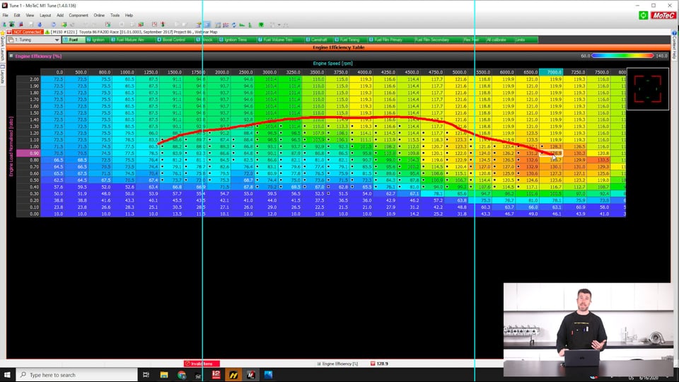
| 25:49 | I actually developed a custom package for our MoTeC M1 that's running on our Toyota 86 development car to do exactly this. |
| 25:59 | So if we jump across to our laptop screen for a second here we can see this is our main volumetric efficiency table. |
| 26:07 | The load axis here is labelled engine load normalised. |
| 26:11 | So that's just MoTeC speak for our load axis for that particular table. |
| 26:17 | But the numbers there, I've done this in the background using M1 build, so this is just a inlet manifold pressure divided by our exhaust manifold pressure. |
| 26:30 | So what you can do here then is start to see where abouts we're actually accessing on this table, you've got all of these little black points here which are zones I've actually tuned. |
| 26:40 | Because one of the problems if you are using iMAP over eMAP as your load axis, it's not always quite as straightfoward to figure out where abouts you're operating inside of the efficiency table. |
| 26:52 | Particularly at high RPM, let's say in our example here, let's go back over, in our example here, our manifold pressure is fixed give or take at 150 kPa so conventionally if we had a lean spot or a rich spot in a log file from that, we would be simply looking at the RPM range and then we know that our manifold pressure is 150 kPa, we can zero in on that particular cell, make our adjustments really easily. |
| 27:18 | However if we actually look at what's happening to our exhaust manifold pressure, and I'll just sort of average this, we can see that the exhaust manifold pressure is constantly changing as we ramp through the RPM which in turn means that our pressure ratio across our engine is constantly changing. |
| 27:35 | And that's what happens if we come back and have a better look at our table here, so let's just full screen this here and let's actually get rid of our graphical view and we'll go full screen on our table. |
| 27:49 | So in a ramp run here, we start with a pressure ratio around about here at about 1.1. |
| 27:55 | As we come up on boost we see our pressure ratio actually peaks, I think from memory it peaks at about 1.4 at about 3500 RPM. |
| 28:04 | And then of course at higher RPM as the exhaust pressure builds, it drops back and we end up getting down to around about 0.9 so you sort of end up taking a bit of a funny line through the efficiency table and it's more important as well to actually look at your logging and log that pressure ratio item to decide where abouts in the table you are running. |
| 28:29 | This allows you again to pinpoint the areas that you need to make adjustments to it. |
| 28:32 | So it's not initially an intuitive system to use, I'd have to say that but I have found that it is very effective. |
| 28:41 | We don't have massive changes in altitude here in Queenstown but I've still been able to test this from around about 250 m above sea level up to I think around about 1500. |
| 28:53 | And we do find that it gives really really stable control over the fuelling, just again because that barometric air pressure is taken into account with the change in our exhaust back pressure so everything becomes automated, obviously the true test would be to see what it does from the bottom of the likes of Pike's Peak up to the top. |
| 29:14 | Now it's important to mention here that this isn't going to account for everything here so it's one thing to be accounting for your pressure ratio across the engine and driving the turbocharger harder and harder as your altitude increases to maintain a fixed manifold pressure. |
| 29:31 | However we also do need to account for and it's a little bit outside of the scope of this webinar but I just want to mention it, account for the fact that you will find particularly if you're competing at the likes of Pike's Peak, if you've got a turbo set up that's optimised for sea level operation, you're almost certainly going to find that you'll end up overspeeding the turbocharger if you want to try and maintain a fixed manifold pressure in the inlet manfold as the car climbs up the hill. |
| 29:58 | And this relationship here between inlet manifold pressure and exhaust manifold pressure also answers one of the other questions I quite often get asked. |
| 30:06 | The example of the likes of a Pike's Peak hill climb car, surely if we have a turbocharger which is sized large enough so that we can produce let's say 20 psi in the inlet manifold at sea level, and we've got that turbocharger size so that we can just wind the turbocharger harder and harder, and maintain that 20 psi in the inlet manifold the whole way up Pike's Peak, right up to 14000 feet at the summit, then surely our engine performance is not going to change. |
| 30:35 | Well the reality is unfortunately yes it will because that is again that narrow view where we're only looking at the inlet side of the engine. |
| 30:43 | So the exhaust side is just as important. |
| 30:45 | What's going to happen there, despite the fact that the barometric pressure is actually dropping, we're accounting for that in our exhaust pressure, because we're trying to maintain that same manifold pressure, as the altitude increases, we've got to increase our wastegate duty cycle to drive the wastegate closed more and more in order to maintain that boost pressure and what this does is it creates an increase in exhaust back pressure pre turbocharger so our relationship, if we looked at that as the car goes up Pike's Peak from the start line to the finish line, is that the exhaust manifold pressure just continually will increase which starts to strangle the flow out of the engine so hopefully when you start looking at the overall picture as opposed to just the inlet manifold pressure you can start to see that we're still not going to end up with the same engine power at the start of the hill climb as what we end up with going across the finish line. |
| 31:39 | Alright let's jump into some questions and we'll see what we've got in here. |
| 31:53 | Alright Ducie54's asked, I'm running an SR20vet with a GTX3076r with a 0.82 housing. |
| 32:01 | At peak RPM my eMAP is equal to boost pressure, 18 psi, is it worth swapping to a 0.62 housing, it's built for hill climbs and street? Look for a start I would say that you're getting a really good result if you are only just equalling your boost pressure at peak RPM. |
| 32:17 | And given that your usage is hill climbs and street, I would definitely think that trying that smaller housing would be probably quite a good idea. |
| 32:27 | You might find that you'll sacrifice a little bit of high RPM power because your exhaust manifold pressure is going to increase but yeah a lot of people fall into the trap of thinking that power is the key component that we're chasing but it's really not, it's about getting that balance between power and response and often a turbocharger that offers maybe 500 or 800 RPM better response, and also is crisper coming on boost as you get back on the throttle after a gear change, or coming off a corner, that will actually make the car overall faster even if you're giving out maybe 20 or 30 horsepower peak. |
| 33:02 | Ken's asked, does manifold pressure work differently with single versus twin scroll turbochargers of the same sizing and how does the back pressure work when using twin turbos such as a 2J or the RB26 on stock setups? OK so the relationship between exhaust manifold pressure versus single or twin scroll, not a lot of difference here, does make it a little bit tricky if we have a twin scroll turbocharger where, as I sort of mentioned previously on our FD RX-7, that's the exact scenario we've got, a lot of people will just fit a single exhaust manifold back pressure sensor and within rights we should be able to expect the pressure to be relatively consistent from one scroll to the other, that doesn't always pan out though which is why I'm personally interested in seeing if we do have any discrepancies there. |
| 33:51 | With a twin scroll versus a single scroll, irrespective of the exhaust back pressure we do tend to find that for exactly the same AR housing, the twin scroll housing will provide better response. |
| 34:02 | So there is a consideration there. |
| 34:05 | All other things being equal, even for a lower exhaust manifold back pressure value, you're likely to find that a twin scroll housing will actually build boost quicker than a comparable sized single scroll housing, of course that's why people go that way in the first place. |
| 34:21 | With twin turbos on let's say the RB26, again in the perfect world you would want to take a sample from both manifolds, both collectors per turbocharger. |
| 34:32 | Again that's not always absolutely possible but it is possible here as well with twin turbos to have a situation where there's a discrepancy in the way the wastegates are adjusted with their spring tension and you can actually get a situation where one turbo is working a little bit harder than another. |
| 34:50 | This is something that will be highlighted if you've got turbo speed sensors on each turbo but also will show up with the exhaust manifold back pressure. |
| 34:57 | So you're not always in a twin turbo situation while you'd think that the exhaust pressure should be the same between both, that's not always going to be the case. |
| 35:08 | Barry's asked, from your experience, what effect have you seen on exhaust manifold back pressure if you increase the turbine wheel size but keep the turbo housing AR the same? Definitely if you go to a larger turbine wheel you're going to see your exhaust manifold back pressure drop. |
| 35:24 | The way I kind of dumb it down it the exhaust, the turbine wheel is kind of a coarse adjustment for getting the flow and response out of the turbocharger and then the turbine housing is kind of a fine tuning so you can't fix a very laggy turbocharger setup just by going to a tight exhaust housing, that's not going to be the solution. |
| 35:45 | Both parts need to be considered in conjunction there. |
| 35:51 | Cmelle has asked, where's the best location for an exhaust manifold pressure sensor input for a naturally aspirated engine, is it somewhere on the header collector? Yeah I would be trying to put that on the collector itself or probably somewhere just pre collector, sometimes where you can physically fit the sensor is going to be the other, or fit the takeoff for the sensor would be the other aspect. |
| 36:14 | Barry's asked, how do you find the eMAP sensor hold up to the pops and bags of an antilag system? I haven't had much trouble with them, I think over time I've had one fail but I couldn't necessarily say that that's just due to pops and bangs, I mean they are living in a relatively harsh environment even with some of the heat taken out of the air source that's going to them. |
| 36:37 | So they're probably not going to be immune. |
| 36:39 | I know a local rally driver here runs in the New Zealand Rally Championship permanently with a exhaust manifold pressure sensor connected up running pretty aggressive antilag system and that hasn't seemed to cause them any trouble with their reliability on their sensors. |
| 36:56 | Matt's asked, how do you use the information gathered from the eMAP logs to tune your camshaft lobe centre angles? As I understand it you can close them up to increase the overlap generally speaking but can you expand on how you do this in practice? This is in terms of the 4G63 drag application. |
| 37:12 | OK good question there so I mean ultimately I don't know if I would use this solely as my tuning tool for cam timing. |
| 37:22 | This is really where we're using the feedback from the dyno but sure the exhaust manifold pressure input does give you some insight into what the engine may want. |
| 37:30 | Particularly if you've got very large levels of exhaust manifold back pressure, what this is going to potentially do is cause some of the exhaust gas to make its way back into the combustion chamber during the overlap period. |
| 37:45 | Basically reducing the volume in the cylinder that can be filled with fresh oxygen, fresh air and fuel so if you've got very high back pressure, chances are you're going to want to reduce your overlap. |
| 37:57 | Ultimately though, much more powerful way of actually seeing what's going on there is just to adjust your cam timing on the dyno and see what the results are. |
| 38:07 | This isn't really specific to tuning a drag engine, we generally find that the engine is going to be more sensitive to changes in the intake cam. |
| 38:18 | The general rule here is that if we advance the timing we're going to end up improving the bottom end performance, if we retard the timing, we end up improving the high RPM performance. |
| 38:30 | I'm talking here generally about either advancing or retarding one cam or both together. |
| 38:33 | The other aspect here though is we can retard one and advance one and spread the lobe centrelines basically to change our overlap so again this is where you may want to investigate if you do have very high levels of exhaust manifold back pressure. |
| 38:49 | Again it'll be a tradeoff though because what you may gain or improve in high RPM where that exhaust back pressure is starting to climb, you're most likely going to be giving away in terms of low RPM performance but again the dyno really will guide you with that. |
| 39:05 | Andrei has asked, how would you use eMAP to MAP ratio with an ITB turbo engine such as the RB26, could you use a pressure sensor per throttle for the MAP input? On the ITB engines, the RB26 in particular, it's not a technique I would use. |
| 39:22 | What I would suggest, because they are quite a specific setup here, I would use this as a conventional alpha N style where your fuel table is RPM versus throttle position, you've got even an overlay or a target air/fuel ratio table related to manifold pressure so you can trim your fuelling targets as boost pressure changes. |
| 39:46 | Then you could if you wanted to, bring in exhaust manifold back pressure as a compensation table because what you will find, and this is really common with the RB26, let's say we've got stock turbochargers on it, let's say we get it onto the wastegate spring pressure, minimum pressure and let's say for example that we can do a run through there at maybe 12 psi of boost. |
| 40:08 | With the alpha N style it actually becomes really easy because at wide open throttle on the ramp run, we are only tuning that one row through our fuel table. |
| 40:17 | So once we've done that at 12 psi and we start increasing the boost pressure, if everything's working properly then the air/fuel ratio should simply track the new target as the boost pressure increases from our air/fuel ratio target table. |
| 40:31 | That'll work up to a point but once we start pushing the turbochargers really hard, let's say we get them up to maybe 18 or 20 psi, you're going to find that at higher RPM because of the climbing exhaust back pressure, you're going to get into a situation where the turbos start to choke the engine and the air/fuel ratio no longer tracks your target, in fact what it's going to do is go pig rich. |
| 40:56 | There are a variety of ways of dealing with this, you can use a 4D compensation table where we just take manifold pressure into account and we trim fuelling out in those ares where it starts to go excessively rich. |
| 41:10 | Alternatively you could do the same with an eMAP trim table as well which would probably be the more accurate way of doing it, using manifold pressure is kind of a bit of a bandaid way of doing it but it does work. |
| 41:21 | That's quite a specific type of engine to tune though and if you do want to learn more about that, I'd suggest you check our archive out there, we've got some specific examples on 4D tuning for the RB26 in particular there. |
| 41:36 | Alright that's brought us to the end of our lesson and hopefully everyone's got a little bit more of an idea on what eMAP is and where it can end up being useful, some considerations for getting that signal into your ECU. |
| 41:47 | Of course if you're watching this in our archive and you've got questions, please ask those in the forum and I'll be happy to answer them there. |
| 41:54 | Thanks for joining us and hopefully we'll see you next time. |
Timestamps
0:00 - Introduction
1:16 - Mostly application to forced induction
2:03 - What does the TIP/EMAP data tell us?
4:16 - Data overview
7:36 - EMAP to IMAP ratio depends on your application
11:53 - Drag racing example
12:36 - Technology is moving the ratio goalposts
13:47 - How do we get this data into our ECU?
21:35 - Using data as a load input
31:39 - Questions


