252 | Introduction to Adaptronic
Summary
In this webinar we’ll be taking an introductory look at the Adaptronic modular series ECU. We’ll cover the features of this ECU and how to navigate the software, as well as a basic work flow to help you get the best results from your tuning session.
| 00:00 | - Hey guys it's Andre from High Performance Academy, welcome along to another one of our webinars. |
| 00:04 | This time we're going to be having an introductory look at the Adaptronic modular range of ECUs. |
| 00:10 | And it's the modular that we've decided to fit to our FD RX7 running a turbocharged 13B. |
| 00:17 | The introductory look though, regardless what particular vehicle or engine combination you're interested in running the modular ECU on, the introduction that we're going to look through here is still going to be applicable, we're not really looking at specific tuning functionality. |
| 00:32 | On the rotary engine we're more just looking at a general tour of the software. |
| 00:36 | And I cover this from the angle of someone who is relatively new to the Adaptronic platform as well. |
| 00:43 | We've had the car up and running now for around about six weeks and it's given me an opportunity to get to grips with the software, how it functions and I'm going to share some of my thoughts, some of my findings with it. |
| 00:54 | Because it is an introduction I just want to make you aware at the start, we aren't going too deep into any of the functionality. |
| 01:00 | That will come with time as we add more and more member's webinars around the specific functionality, specific setup such as cold start tuning etc. |
| 01:10 | But for now, this is just getting to grips with the particular software and how it's laid out, where to find all of the functions and how to go about setting up some of the basics that you'll need. |
| 01:21 | As usual we will have a question and answer session at the end of today's lesson. |
| 01:25 | Just broadly the engine combination that we are running here is a completely stock 13b engine, around about 100,000 km on it. |
| 01:33 | It's running a TurboSource exhaust manifold with a Borgwarner EFR 8474 turbo, Turbosmart external wastegates and it's running a set of ID1300 primaries and a set of ID1700 cc secondaries so it's about all you really need to know about the engine setup that we are running itself. |
| 01:56 | If we jump across to my laptop screen, let's have a quick look through Eugene, which is the Adaptronic tuning software. |
| 02:04 | Now there is a reasonably user friendly intuitive structure to this. |
| 02:09 | We've got a bunch of menu structure across the top here that we can choose from. |
| 02:15 | Right now, and we'll have a look at this in a bit more detail, we're obviously looking at our fuel tuning map. |
| 02:21 | And we've got some of our key parameters out here on the right hand side that we may want to be monitoring while we are performing our tuning. |
| 02:29 | We will start with the basics though which is some of the initial setup functionality you're going to want to go through. |
| 02:36 | So in particular here we start on our home tab and we can start here by opening or saving an ECU file. |
| 02:47 | With the Adaptronic, every ECU seems to have its own specific way of going about this but when we make a change that is written in real time to the ECU, so there is no need to actually store your changes, as soon as you make a change to any of the tables, any of the parameters, those changes take place instantly and you don't need to save them. |
| 03:07 | We've got some aspects here just for the personal preference of the tuner, you can set your units to be in metric or imperial. |
| 03:16 | You can also tune in lambda or air/fuel ratio units. |
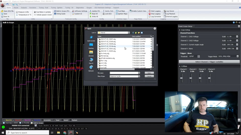
| 03:20 | Coming over to our tools and configuration, one of the really nice functions with the Adaptronic is it does have a built in scope so we'll click on that here. |
| 03:30 | This will take us through to our scope. |
| 03:32 | You can set this up for up to four channels, we can see the channels that are selected here on the right hand side. |
| 03:39 | Generally one of the more useful functions with this is to check that we are getting valid inputs from our ref and sync, from our engine position and engine speed sensors and that's exactly what we're showing here, along with our current engine angle, you can actually pause this as well. |
| 03:58 | So you can set it up and use it just like a normal oscilloscope, you can set the scale per division so that you've got full range of all the parameters. |
| 04:07 | So we can see here the yellow trace is from our engine speed input. |
| 04:13 | The red trace there is engine position. |
| 04:16 | So you can go through there and basically count the number of teeth that are being seen. |
| 04:20 | Other important thing with a reluctor or VR sensor, magnetic sensor is the polarity of the inputs is quite important. |
| 04:29 | We can see here, if I just try and poorly draw over this trace, it comes up through the zero volt, rises, I am doing a terrible job of drawing this but the important thing here is that when it drops down through zero, it drops almost vertically so this is what we want, this is a falling edge trigger. |
| 04:50 | So it's really important because if you've got the reluctor sensor wired up around the wrong way at the wrong polarity, you can still get the engine to run. |
| 04:58 | The signal will exactly be an inverse of what we've got there but the problem with that is that as the engine RPM changes, we get what's called timing drift. |
| 05:08 | So it's really important to make sure the polarity is correct there and the scope will help you with that. |
| 05:14 | Also our purple line that we've got in here which again I'm poorly drawing over the top of, this is our current engine angle so what we should see with this is it should rise smoothly and evenly like we've got it doing there, up to 720 degrees, drops back and basically starts again. |
| 05:30 | So really good function there for just dialling in some of the potential problems you may have, particularly if you're dealing with a engine position or engine speed position sensor setup that you're not 100% sure exactly what you are dealing with there. |
| 05:45 | Moving on over to our configuration we can read everything out of the ECU, write everything back into the ECU and we can also update our firmware there. |
| 05:57 | Interestingly we can actually see since I've connected today, it's flashing down the bottom right hand corner that we do actually have a firmware update. |
| 06:04 | Not going to do that right now but it's always a good way to keep you up to date with the latest firmware option, making sure that there's no bugs or anything in the background that you're not aware of. |
| 06:18 | On the right hand side here we've also got our built in logging. |
| 06:21 | So we can start and stop our logging here. |
| 06:24 | We've got a log viewer as well as our log playback and then we can also convert our log file. |
| 06:31 | So this is actually one of the areas, we'll have a look at this once we do a ramp run, this is one of the areas that I feel maybe the Adaptronic does leave a little bit to be desired is in the internal logging. |
| 06:41 | As we'll see again once we jump into it, it is a little bit clunky to use and not particularly useful in pinpointing exactly what's going on. |
| 06:50 | Certainly better than nothing but I found when I was doing my tuning on the FD RX7, I was relying, for the main part on using MegaLogViewer HD and that's where the little log converter comes in, if we click on this. |
| 07:05 | Basically you can select your log file, open a log file and then you can convert that to a .CSV file so the log file that I've just created recently here, no not that one, anyway one of those log files, the Adaptronic uses a .ALG format for internal logging. |
| 07:27 | Which is useful because this also includes a copy of the map. |
| 07:30 | So particularly if you are getting technical support from Adaptronic, if you send them a log file, it basically gives them a copy of your current calibration. |
| 07:39 | Which means that they don't have to go guessing as to what your problem might be, they can align the data that is in the log file with what is actually in your current calibration, making sure that they can pinpoint problems quickly. |
| 07:52 | But personally for my own preference here anyway, I found that using the logging in conjunction with MegaLogViewer HD just allowed me a little bit more flexibility in displaying the data exactly where I wanted it to be, what I wanted to see and doing a little bit more in depth analysis particularly along the lines of using the histogram function in MegaLogViewer. |
| 08:15 | Obviously this isn't a webinar on MegaLogViewer, if you want to learn a little bit more about that, check out our MegaLogViewer HD webinars in our member's archive at a later point. |
| 08:25 | So that covers our home screen there, our home tab I should say. |
| 08:29 | We'll move across now to our inputs. |
| 08:33 | Basically the work flow here when we are setting up the ECU for the first time is pretty intuitive, we're going to basically work our way through those tabs. |
| 08:41 | With each of those tabs there are sub tabs below and again we're just going to work from left to right. |
| 08:47 | So with any ECU when we are setting it up, the engine details is one of the key points because also the Adaptronic offers VE or volumetric efficiency tuning mode. |
| 08:57 | We do want to make sure that our engine parameters such as our engine capacity is correct there. |
| 09:02 | That'll have a big effect on the final results for our volumetric efficiency table values. |
| 09:07 | If we've got this set up incorrectly then we're going to be baking in errors into our VE table and the corrections won't be working properly. |
| 09:15 | Now when we are dealing with a stock engine obviously this is pretty self explanatory, we're dealing with a 1300 cc two rotor rotary engine, no big surprises there. |
| 09:24 | But there can be subtleties where someone's maybe installed a stroker kit taking maybe a two litre 4G63 out to 2.2, 2.3 or 2.4 litres and we really want to be able to account for that with our capacity. |
| 09:35 | Moving down, as I've already touched on, we've got our number of cylinders or our number of rotors. |
| 09:41 | Obviously you can have the option here to tick this little box if you've got separate banks of cylinder for V configuration engines. |
| 09:48 | And we've got our firing mode here so we can choose to fire in this case every 360° or two stroke. |
| 09:55 | Or conventionally for a piston engine we would be normally 720° or four stroke. |
| 10:00 | So that's our very basics there. |
| 10:03 | We'll move across now to our triggering and once we've got our engine details set up, the triggering is the most important information that the ECU needs. |
| 10:12 | This gives it information about the engine speed and position, we've already looked at that briefly with our scope there and if this isn't coming in correctly and being decoded correctly then nothing else is essentially going to work. |
| 10:23 | As with most ECUs these days we've got the ability to choose a base trigger mode so sometimes the heavy lifting has been done for us, we click on that drop down menu we can see there's a fairly extensive list of options there. |
| 10:37 | Interestingly though if we come back up, if we can find it in here, we do actually have a trigger mode in here for Mazda RX7 FC, FD and a few other options there. |
| 10:51 | You'd think that would be the trigger mode for our completely stock standard triggering on our FD RX7, it is not. |
| 10:59 | Instead general is the mode that we want to be choosing here. |
| 11:02 | We also have our angle increment and our base angle so I'm not going to get too deep into this, basically defines the angle between trigger inputs, in this case we can take our number of teeth, divide that by 360, it'll give us the angle increment, our base angle is essentially setting our base ignition timing so that we can align the timing on the laptop screen with the timing that the ECU is actually providing. |
| 11:30 | What we're actually seeing at the engine if we use a timing light. |
| 11:33 | Little bit fussy with rotary engines as well because there is a leading and trailing plug so we need to make sure that we've got this right. |
| 11:41 | We can check this using our timing lock enable so at the moment we've got no timing lock, this is what we want to see when the engine is running, if we click on that drop down menu, we can have timing lock normal in which case we can just set a timing value. |
| 11:57 | It will override all of the table values and give us one fixed timing value. |
| 12:02 | Or there is also a specific rotary mode that will give us a trailing, leading and trailing split and we can time those up. |
| 12:10 | Particularly with the earlier RX7s, there was a timing mark for leading and trailing, not so easy on the FD RX7 because there is one mark so you need to know what you're looking at there. |
| 12:20 | Down the bottom here we can see what our RPM is doing, at the moment I've just got the engine sitting here idling. |
| 12:26 | So that's our general settings, once we've got our general settings set up, we can go into our specific triggers. |
| 12:30 | We've got three trigger options here, we're only using two of these, the third one would be perhaps if we were running a variable valve timing engine and we have cam position as well as a synchronisation input. |
| 12:41 | We'll have a quick look over at our trigger one and we can see that we've got this set up as a reluctor with falling edge which I've already talked about there. |
| 12:49 | Trigger two essentially exactly the same, also there is a reset mode and a reset type. |
| 12:57 | If you hover over any of these as well there is some information, usually about the particular function that you are looking at. |
| 13:05 | Once you've got it set up though, all relatively easy to do and pretty simple to get yourself up and running. |
| 13:12 | Moving on, the next set of tabs that we've got or the next tab I should say, covers our analog inputs. |
| 13:20 | So setting up the inputs to the ECU and this is really going to depend on exactly what you're doing, what you're running. |
| 13:25 | We can see it's again pretty self explanatory here, for example we've got our MAP sensor input. |
| 13:32 | So the Adaptronic modular ECU does have an onboard MAP sensor and an onboard exhaust manifold pressure sensor as well. |
| 13:41 | Which also allows an interesting tuning mode, you can choose pressure ratio as one of the, as the load axis. |
| 13:48 | So pressure ratio essentially, as its name implies, the ratio between the inlet manifold pressure and the exhaust pressure. |
| 13:54 | So if you are running eMAP that is one option available for you. |
| 13:58 | We also have MAP filtering options here and there's some information in the help file about how to, how you should set this up so this takes into account that if we actually sample the manifold pressure signal at a very high frequency, we tend to set the MAP signal oscillate as the intake ports open and close, the intake valves open and close. |
| 14:20 | So depending on where abouts we actually sampled the manifold pressure signal can have quite a dramatic influence on the way the engine runs. |
| 14:27 | So in this case it's averaged over 180° cycle and there is also an adjustable filter time here, not going to get too deep down into the weeds with that. |
| 14:36 | If we click on our intake map one, we've got our IMAP one source so we can see here I'm using an external IMAP sensor that's wired out into the engine bay. |
| 14:45 | We've got the option to click on this and select our internal IMAP, our internal EMAP etc. |
| 14:53 | Interestingly this ECU actually ended up with a dead IMAP sensor on arrival which is quite interesting. |
| 15:01 | I'm not quite sure exactly what went wrong there but yeah we found that when we first went to get the engine running. |
| 15:08 | We've also got the sensor type so in this case we have selected generic which allows us to configure the table for the calibration of that sensor. |
| 15:18 | If we click on that table, we can see there are a set of pre configured options there. |
| 15:22 | For generic we can click view and edit table and we can see that we've got the ability to set that up, we've got 20 kPa at 0.2 volts, 396 kPa at 4.8 volts so you're just going to essentially select that based on your particular setup. |
| 15:40 | We'll move through and have a quick look at our temperature sensors and again no big surprise here, we've got all of the available sensors listed down the left hand side. |
| 15:50 | If we look at our engine coolant temperature which we're on at the moment at the top, again we can choose from a set of pre configured options. |
| 15:58 | Interestingly here, I thought it was a little bit strange that there was no pre configured option for what I'd probably think is the most common sensor I find which is the Bosch NTC sensor. |
| 16:09 | So we actually had to set up a calibration here which is in this table. |
| 16:13 | Also the source which actually ended up being a little bit of a problem for us due to the way our wiring harness was constructed. |
| 16:24 | Because of some changes we made with the mechanical configuration and the sensor location, we ended up with the actual pin for manifold air temperature being used for an auxiliary temp sensor and we found an actual firmware bug in there which Adaptronic have since fixed which prevented us using that. |
| 16:42 | So anyway probably the pro tip there is wire up as per the user manual, there are dedicated pins for the likes of our air temp, fuel temp, oil temp etc and that's what you'll be on if you have this default setting listed here, obviously click down on this and you can choose from any of the available inputs. |
| 17:02 | Then we've got our table to adjust the calibration there, resistance based on engine coolant temperature, nothing particularly tricky about all of that. |
| 17:12 | Fuel temp, I'll just touch on this here because this is quite interesting, we are using a flex fuel sensor, the continental ethanol content sensor. |
| 17:22 | Which does give us fuel temperature as well as ethanol content, it's all in the one digital signal so you can select flex fuel sensor if you've got one fitted as your fuel temperature source, you can see that at the moment our fuel temperature's sitting at 28°C. |
| 17:37 | We've got user temperature here on the left hand side as well so we've got our intercooler in temperature, ambient temperature and we are using our user three channel as well. |
| 17:50 | Coming down the bottom here as well, if we click on biasing and filtering, interesting terminology here, I'm not quite sure why they've selected to use the term biasing but essentially this is the ability to turn on or off the built in pull up resistor depending on whether you've got these tick boxes ticked. |
| 18:08 | So this is important with the NTC thermistor style sensor, it is a two wire sensor and generally with a analog, a dedicated analog temperature input on an ECU, this will have an internal pull up resistor to five volts without that the sensor basically won't give us a signal. |
| 18:25 | But there are situations, particularly if we are piggybacking a factory ECU, where we will want to disable that pull up and that'll allow us to share that signal with a factory ECU or if you're bringing the sensor in from a analog voltage input with an external pull up that's wired as part of your harness, again you'd want to disable that so some options there depending on exactly what your wiring configuration is. |
| 18:50 | Moving on we'll have a quick look at our liquid pressure sensors. |
| 18:54 | So probably no rocket science here, we've got oil pressure and fuel pressure. |
| 18:57 | Interestingly this is sort of the limitation here, is in the terminology, liquid pressure, we've actually got a EMAP sensor wired up as well, exhaust manifold pressure sensor wired up to one of our user pressure inputs as well as a pre intercooler boost pressure sensor so it's not just liquid, it's just depending on exactly what you want to set these up, we've got our user channels here, user pressure one through to four so that should be enough to cover most of your requirements. |
| 19:28 | Moving down, pedal position, no rocket science here, we are running drive by wire on this particular engine so we have two throttle position or pedal position sensors. |
| 19:40 | Terminology's quite tricky here or quite specific. |
| 19:42 | With drive by wire, I like to call them pedal position or accelerator pedal position and then throttle position refers to the throttle plate position. |
| 19:52 | Pretty easy to go through and do this though, all you have to do, in this case we've got pedal position calibration one at 0% or closed throttle. |
| 19:59 | We simply make sure we are at 0%, click learn voltage and that will show us what the current voltage is. |
| 20:04 | We can also see live what that voltage is doing, it's actually sitting slightly higher at 4.55 volts. |
| 20:10 | Then we do the same with our pedal position two, 0% then we simply go to wide open throttle, obviously with the engine not running and we can set our two 100% throttle position sensors. |
| 20:24 | Not too tricky to get your head around there and once you've got that set up you can also watch the pedal position which is here, we can move our throttle and we can see that that's going to move hopefully nice and smoothly. |
| 20:37 | We've also got our external 0-5 volt inputs and this is one of the areas where I think there's probably a little bit of a limitation in the software. |
| 20:48 | We're actually not using a analog voltage input that we want to display in percent which is our only option here. |
| 20:56 | This is actually wired up, our external input one and two are wired up to thermocouple amplifiers. |
| 21:04 | So we've got at the moment here, we can see our voltage is 2.27, 2.29 volts. |
| 21:10 | 569%, that's actually °C so this is our exhaust gas temperature. |
| 21:18 | So a little bit frustrating that we can't actually select units for this because I'm not convinced that everyone wants to wire up something that will be displayed in percentage but it doesn't really matter, as long as you understand or know what you've wired up and how it's configured, that's going to display, if we click on view and edit table, we can see we've got our voltage there, zero volts equals 0°C, five volts is 1250°C. |
| 21:45 | Obviously you can also calibrate that in °F if you prefer. |
| 21:50 | Looking at our servo input here, and the setup we've got here again a little bit of a limitation on the units used, in this case though not really a big problem, I'm using this for a wastegate position sensor which has actually been quite interesting. |
| 22:07 | So if we click on view and edit table, again it's a 0-5 volt input. |
| 22:12 | I haven't actually calibrated this particularly accurately but you sort of get the idea. |
| 22:17 | This is still a bit of a work in progress with this particular car. |
| 22:21 | We're currently seeing 2.23 volts out of that sensor and that's showing 22.3%, really should be showing 0% at the moment. |
| 22:31 | But interestingly with this data what we can see is how the wastegates tends to push open, even before we get to peak boost but it's more of a tuning aspect than the Adaptronic itself, just some interesting software. |
| 22:41 | We've got the ability to set up an atmospheric pressure sensor for barometric pressure, depending on how exactly you want that to work. |
| 22:48 | At the moment we're using our built in EMAP sensor which is on the ECU there for barometric pressure and we can see that that is showing 95.4 kPa. |
| 22:58 | Now interestingly again here this is something I found a little bit unusual in that normally if you're using the onboard MAP sensors, I find with most ECUs the calibration is pre defined because let's be honest, they obviously know what their built in MAP sensor is. |
| 23:14 | In this case I actually had to email Adaptronic support and find out what the calibration was and then manually enter that myself in this table so as it turns out it's a pretty common four bar MAP sensor but again just sort of something that you do need to be mindful of if you are setting this up. |
| 23:30 | We've got the ability to use knock control, not something that I am using at the moment. |
| 23:36 | We will dive into this but probably not in a rotary engine. |
| 23:39 | The reason for this is on rotary engines, personally I'm not a big believer in knock control. |
| 23:45 | The reason for this is the rotary engine is very very susceptible to damage from almost any level of knock, particularly if you are running factory apex seals. |
| 23:55 | And as part of the knock validation and calibration setup, you really do need to actually purposefully induce some level of detonation to make sure that the ECU is able to correctly detect knock. |
| 24:06 | So not something I'm particularly comfortable doing with a rotary engine. |
| 24:10 | Normally with a rotary engine, again particularly with factory seals, you're going to know if the engine has suffered from knock because it won't go any more and the apex seals will be embedded somewhere in the back wall of your dyno cell so pretty easy to tell. |
| 24:23 | Nice function though with the Adaptronic ECU, and I don't why more ECUs don't do this, it actually has a built in headphone jack on the ECU so you don't need an external audio knock detection module which I normally use when tuning, just plug a set of ear buds straight into the ECU and you've got your knock audio coming straight out of that. |
| 24:45 | And that is what we've got here, our knock headphone volume control as well. |
| 24:51 | We've got an ethanol sensor as well which, as I've already mentioned, we've got wired up. |
| 24:56 | So this needs to go to a digital input, it's a digital square wave signal, we've got that wired up to our crank angle sensor three input. |
| 25:05 | So all pretty straightforward, I'll just cover off a couple of these quickly now. |
| 25:09 | So we've got some setups for our wheel speed and gear detection and gear detection as well, as well as a range of digital inputs, again, just depending on what exactly you want to do. |
| 25:21 | None of this is particularly complex, it's all pretty self explanatory and user friendly. |
| 25:26 | We'll jump across to our outputs now and one of the key ones here is setting up our fuel system. |
| 25:33 | So how that works, let's click on fuel system and for a start we've got the type of regulator used. |
| 25:39 | This has a big impact on the fuel pressure that the ECU is expecting which in turn has a big impact on the amount of fuel that will be delivered through the injector for a given pulse width. |
| 25:50 | So in this case we can see we've got manifold referenced selected for our fuel pressure regulator, this is a conventional old school style fuel system. |
| 25:58 | On modern engines it's more common to have a fixed fuel pressure. |
| 26:01 | If we click on our drop down menu, obviously fixed pressure regulator is the other option there. |
| 26:07 | We can also set in our nominal fuel pressure. |
| 26:10 | So this is our nominal differential fuel pressure or base fuel pressure. |
| 26:14 | Typically, there's no golden rule here but typically on a MAP referenced regulator we would choose probably 300 kPa, 43.5 psi. |
| 26:24 | I've actually bumped this up a little bit just because when we do introduce some ethanol content into the calibration here, we're probably a little bit marginal on our injector size so I've just given myself a little bit more head room by going to 3.5 bar, 350 kPa rather than three bar. |
| 26:39 | Now that's if everything fails, sorry if your fuel pressure sensor fails or you haven't got one fitted. |
| 26:47 | However in this case our fuel pressure modelling which is our next option, we can choose to actually measure that directly from our fuel pressure sensor. |
| 26:56 | So this means that if our differential fuel pressure moves around or changes then the ECU can automatically compensate for this. |
| 27:03 | So this is actually quite nice, you'll see that sometimes if you're getting near the limit of the fuel system or there's a voltage drop to your fuel pump, at high RPM and high boost we can start to see our differential fuel pressure start to drop away and this allows us to actually, or the ECU to compensate for that, so keep everything running the correct fuelling. |
| 27:24 | We've got here our fuel pressure used for our calculation, our fuel pressure and our differential fuel pressure all calculated. |
| 27:32 | And we can also trim the fuelling for fuel density which is calculated from our fuel temperature so if you've got fuel temperature, that can be used as well. |
| 27:41 | We'll move down, we've got our primary and our secondary injectors so this is really critical to any volumetric efficiency based fuel system, making sure that the injectors are correctly characterised and again Adaptronic have done a lot of the heavy lifting for us here. |
| 27:56 | We've got our type of injector and if you click on search there's a reasonably extensive list of injectors that are pre defined here. |
| 28:03 | So this will give you all of the correct offset as well as short pulse width adders so that the fuelling will be as accurate as possible. |
| 28:13 | All of the information is on the injectors is also listed down here so exactly the same for our secondary injectors. |
| 28:20 | Now on the rotary engines, typically we're always going to be running staged injection so I'll just quickly touch on that as well. |
| 28:28 | So we've got in this case the number of stages that are available. |
| 28:33 | Now I think there's either the ability to either run up to three or possibly four stages on the Adaptronic, I know that Andy did a lot of work around the RX8 platform which in some applications does run triple injection stages so a lot of flexibility around here. |
| 28:48 | One of the really nice features, this is probably the most sophisticated and kind of faultless from the tuner's perspective in staged injection models I've come across, there's not really a lot of work to do so I'll just explain that here. |
| 29:01 | So first of all we've got our minimum off time for stage one. |
| 29:05 | So this defines the minimum amount of time the primary injectors must be switched off before they can start again. |
| 29:11 | So it's an around about way of essentially limiting the maximum duty cycle that the primary injectors will run to. |
| 29:17 | So in this case, two milliseconds. |
| 29:19 | The problem is with this the maximum duty cycle they'll run to actually is dependent on our RPM because the two millisecond time there becomes a different percentage of our cycle time as our RPM changes. |
| 29:32 | Anyway it does work pretty well just leaving it set to two milliseconds which is the default value. |
| 29:38 | We then have our, it's calculating here based on our differential fuel pressure, the current flow from our primary and our secondary injectors and if we click on our two stage injection map here which you can get to from a couple of places, this is essentially what percentage of fuel is going to be delivered via our secondary injectors, or primary injectors for that matter. |
| 30:01 | So we've got our load axis which is our inlet manifold pressure, we've got our RPM axis on the horizontal axis so you might be thinking, how does this work when this table is filled with values of zero? So if you want to set up your engine so that the maximum amount of fuel is being delivered, basically we're running equal pulse widths on primary and secondary injectors, we can simply leave this table set to zero. |
| 30:26 | What the ECU will then do is automatically in the background drive the primary injectors as hard as it can, keeping in mind that two millisecond off time limit that we've programmed. |
| 30:38 | Once it gets to that point to supply additional fuel, it will then start adding in the secondary injection so we don't need to actually adjust this table, all of the hard work's done for us by the ECU. |
| 30:51 | On the other hand that may not be the only way you want to run staged injection. |
| 30:55 | On a naturally aspirated engine it's not uncommon to have a secondary set of injectors which are fitted outside of the inlet trumpets, primaries down by the inlet valves and you may want to actually stage fully onto the secondaries at high RPM and high load in which case what we could do there, obviously we would be at 100 kPa, we could just basically bring this in to be 100% and that's going to achieve our aim there. |
| 31:24 | Now interestingly, another nice feature which I've just used there, control Z will undo a change that you didn't want to make. |
| 31:31 | So you've got a lot of flexibility in how that staging is set up there. |
| 31:37 | We've also got our ignition control here so we'll quickly have a look at our output control, so we can set our type of injection, in this case we've got direct fire rotary with two plugs per cylinder with split angle, obviously that is specific to our rotary engine, we've got all of the different options in there depending on how your engine is configured. |
| 31:57 | How we want to fire our ignition system, we've got the number of ignition outputs used here. |
| 32:03 | Obviously if we are running direct fire on a rotary, we've got four channels being used. |
| 32:08 | We've got our ignition sense, so this is the way the ignitor is driven, so this is going to depend on the type of ignition system you're using. |
| 32:16 | Falling edge is typical but there are a few unique systems here where we want to run rising edge, you do need to be mindful of this because if you get this around the wrong way, you can end up burning out your ignitor module. |
| 32:28 | Honda for just one example runs the opposite way there. |
| 32:33 | Nothing else really too special to look at there, we'll just move across lastly to our outputs here and this gives us a list of our outputs. |
| 32:43 | So if we do want to set up something in particular, like you can see here we've got our wastegate one duty cycle, you can set the function up here on the top right by clicking on it. |
| 32:53 | You can also select how this will be driven. |
| 32:57 | So in this case invert actually caught me out as well, you need to be careful with that. |
| 33:01 | Basically that will give us zero or 100% duty cycle in opposite ways so the problem with this is if you've got inverted which is what we had originally when I first set up the boost control, we get a situation where the boost control will be giving us maximum boost when we want minimum boost. |
| 33:21 | And that can be a little bit dangerous obviously particularly if you don't have a boost cut set up. |
| 33:27 | We've then got pulse width modulated enabled which we've got ticked so this will allow us to pulse width modulate that output. |
| 33:34 | Again that's pretty important there with a boost control solenoid which we want to cycle. |
| 33:43 | Generally with a wastegate solenoid we're going to find that it'll want to be somewhere around about 20 - 30 hertz. |
| 33:50 | So at this point we've sort of covered most of the input and output setup. |
| 33:54 | We'll come across here and quickly have a look at our functions. |
| 33:58 | I'm not going to go into too much detail here, there are some pretty specific functions. |
| 34:02 | Engine protection, quite a useful one understandably, we've got for a start, our rev limit, I've got the ability to set that up. |
| 34:10 | Need to be a little bit careful here as well with our limiting, how we set that up, whether we're using fuel cut or ignition cut. |
| 34:16 | Generally fuel cut gives us a softer limit and again with rotaries they are a little bit sensitive to this. |
| 34:23 | A lot of piston engines as well, the valve train doesn't take too nicely to harsh ignition cuts so fuel cut is our option there. |
| 34:30 | If we look at our RPM limit versus coolant temperature, we'll bring that table up and we can see what our RPM limit is. |
| 34:38 | You can see that I've dropped that off at 120°C just to give a little bit of engine protection there. |
| 34:44 | Also we've got, if we come back to that, we can set up a boost cut. |
| 34:48 | Some more interesting aspects such as oil pressure and oil temp limiting. |
| 34:52 | Fuel pressure as well, if we start to get our fuel pressure drop off, we can actually also set a lean out margin as well if we've got air/fuel ratio coming through into the ECU which we'll look at in a second, over voltage, EGT, turbine speed etc. |
| 35:07 | Basically as many or as few as you want. |
| 35:09 | We've also got traction control which we haven't touched on yet with our own tuning, anti lag which we won't be doing on our rotary engine and if we come over here, there are some specific functions here which Adaptronic have added in. |
| 35:24 | Not too many ECUs I'm aware of will actually run a factory twin turbo system. |
| 35:29 | So they'll do that as well as specific to the rotary engine, it will actually run the factory oil metering pump if you want to go down that path. |
| 35:37 | We've actually decided to run pre mix in this particular vehicle but again, up to the individual there, it has the ability to run it, it's a stepper motor style control there for the oil metering pump. |
| 35:51 | Coming over to our serial or our communications in general, in this case we are using CAN communications. |
| 35:58 | it's got two CAN buses, we'll click on CAN one here. |
| 36:01 | You can set the transmission rate, bit rate there which is 1 Mbps. |
| 36:05 | In particular here we are using a MoTeC PLM wideband that's coming into the Adaptronic via CAN so that gives us a CAN based wideband, no chance of our air/fuel ratio data getting inaccuracies coming in due to ground offsets etc. |
| 36:22 | We also can set an output more as well so that it will communicate with additional modules so got that all set up, we'll move onto some of our tuning functions here. |
| 36:34 | Which is obviously the main part once you've got everything set up. |
| 36:37 | So let's come into our tuning modes. |
| 36:41 | So we'll move, again we'll start from our basic setup. |
| 36:44 | So we can choose whether or not we want to run dual maps or single maps. |
| 36:48 | We can also choose here to have individual correction maps for cylinders or rotors. |
| 36:54 | So basically you can set this up to be as simple or as complex as you want it to be. |
| 36:59 | Interesting aspect here is the temperature correction mode. |
| 37:02 | So you can choose to use a charge temperature estimate which in Adaptronic lingo is manifold heat soak percentage. |
| 37:09 | Or you can use the conventional setup where you use the separate coolant and air temp correction map. |
| 37:17 | So using the manifold heat soak table, that actually happens over here. |
| 37:21 | If we have a quick look at that table. |
| 37:23 | Basically this is a 3D table that defines the relationship between charge temp vs our coolant temp and intake air temp. |
| 37:33 | The premise behind this is at low air speeds, so idle, low RPM, there's a lot of time for the air to draw temperature from the inlet manifold at the ports etc so the actual charge temperature entering the engine is going to be a lot closer to our coolant temperature than what we're measuring with an air temperature sensor. |
| 37:51 | On the other hand at high air speeds, we're going to be closer to our air temperature so we can actually define that. |
| 37:58 | So you can see at low air speeds down here at idle right now where we are we've got a charge temperature estimate probably around about 65% or thereabouts. |
| 38:08 | Right out to higher RPM and higher boost we're dropping down to 15% so predominantly we're bisasing towards our inlet air temperature. |
| 38:18 | Getting onto our fuel map itself. |
| 38:21 | So we already had a really brief look at this and nothing particularly out of the ordinary here, we can set this up to display both graphically and numerically. |
| 38:30 | Alternatively you can show just the numbers or these little icons over here on the right hand side of the screen basically help you through that so we can show just the grid view, we can show just the graphical view or that split view we had before. |
| 38:44 | This little icon here to the right, this will also bring up our monitor panel so we can see all of our key parameters. |
| 38:52 | Obviously pretty important, in particular here we've got our lambda versus our lambda target which is going to be pretty important while we are doing our tuning. |
| 38:59 | Some of the aspects here, what we'll actually do is get up and running in a second on the dyno and have a look at making some changes so we can see we've got a cross hairs showing where we are sitting on that table. |
| 39:09 | If we want to make changes to our axis setup we can double click on the axis and this will bring up the ability to set our axis up however we want. |
| 39:18 | There's a few ways of doing this so at the moment we can just set up our maximum axis break point, our minimum axis break point and then we have the ability to set up the number of points we're going to have. |
| 39:29 | So at the moment obviously 13, pretty self explanatory, it shows you the maximum number that we can have for this table is 31. |
| 39:35 | So quite high resolution. |
| 39:38 | And then you can set up these values yourself in here. |
| 39:41 | So pretty easy to do . |
| 39:43 | Alternatively if you're up and running, you've already got your engine tuned and you've decided you want to insert or maybe delete one of the columns or rows then you can do that as well using the insert and delete functions. |
| 39:54 | If you are ever wondering, or have lost yourself and you don't know what one of the controls is, right clicking here will give you a full list. |
| 40:02 | So as I just mentioned there, we've got insert column, delete column. |
| 40:05 | For the rows we use shift insert and shift delete so that'll also interpolate as well so you don't have to do too much hard work yourself. |
| 40:16 | What we'll do though is I will just get up and running here and we'll look at doing a little bit of steady state tuning and see what we've got going on here so we'll just get ourselves running at maybe around about 2500 RPM. |
| 40:32 | So we'll just use the dyno to bring our speed up here. |
| 40:37 | Alright so one of the nice functions here, I like to be able to just automatically jump to the particular cell that we're currently accessing and the space bar will do that. |
| 40:48 | So we can see the white cell that's highlighted, that's the current cell so if we're going to make adjustments, that will be the cell that is adjusted so we can see out here on the right hand side, we've got our measured air/fuel ratio, lambda versus our target lambda, so at the moment we can see that we're pretty much on the money, we don't need to make any changes there. |
| 41:08 | However another nice feature with the Adaptronic which we can use more in line with doing our ramp runs, just to see where exactly we're accessing through a particular part of the table, so we know where to make changes, we can press the M key and that will, sorry not the M key, that marks the cell as tuned, we can press the T key and that will give us a trace that stays up as we move through the cells. |
| 41:36 | And then we can come back to idle and we can have a look at exactly where we made the, where the ECU was accessing while we were tuning. |
| 41:46 | So in order to make actual changes to the individual cells, we can use the page up and page down key. |
| 41:54 | So that adds 1% every time we press it. |
| 41:57 | If you want to make finer changes, if you hold down the control key and use the page up and page down, that will make changes of a 10th of a percent. |
| 42:05 | If we just come out here into an unused part of our map for a moment, we can see we can use the shift key and highlight, we can basically highlight a block of cells and make group changes to those. |
| 42:17 | We can directly enter values if we want to. |
| 42:20 | Another common way I use the tuning, let's just again just go to an area where we aren't actually accessing, so 5500 RPM there, we can make a percentage change by pressing the P key and then let's say we want to add 10% to that, we will enter 10 and that will make that change, again control Z will undo that change. |
| 42:39 | Obviously -10% would have the opposite effect. |
| 42:42 | So pretty easy to manipulate the numbers in our tables and make the sort of changes we need to. |
| 42:49 | Now at this point I've skipped over one of the other aspects of the volumetric efficiency based fuel model which is the fact that it works in conjunction with our target lambda table so we can see that our target lambda, target AFR table is over here, we'll click on that and that'll bring us over to that table. |
| 43:07 | And we can see we can set up our target air/fuel ratios based on whatever we want the engine to be running. |
| 43:12 | You can see we've got our typical load axis of our inlet manifold pressure vs RPM. |
| 43:18 | We've got an area here in the higher RPM cruise set to lambda one. |
| 43:22 | Generally we'd run richer air/fuel ratio or lambda targets for a rotary engine than what we would run for a piston engine but you can manipulate this to suit. |
| 43:33 | The idea of course behind the volumetric efficiency based fuel tuning is that what we do is we start by setting our target air/fuel ratios what we want them to be or where we want them to be. |
| 43:47 | We then tune the VE table to achieve those targets. |
| 43:49 | Once we've done that, unless we make a mechanical change to the engine that will affect the VE, we don't change the VE table again. |
| 43:55 | And instead if we decide we want to see how the engine responds with a richer air/fuel ratio, we can make those changes directly into our lambda target table and the ECU will do the hard work and get us where we want to be. |
| 44:07 | Moving along, we've also got transient correction here, so transient enrichment and this actually uses the fuel film modelling as opposed to a more simple rate of change of TPS so it can actually properly model the fuel film. |
| 44:23 | So set up correctly, that will do, give us the potential to do a better job of getting our transient enrichment dialled in. |
| 44:32 | Interesting other aspect here which I don't see in too many ECUs is it gives us a predicted MAP table so if we look at that here, based on our throttle position versus RPM it gives us the manifold pressure and this allows a look up table essentially that can give us quicker response sometimes on a transient, does need to be set correctly in order to allow this to work. |
| 44:58 | Pretty much look at just about everything else here, we've got our cranking enrichment of course which is pretty self explanatory, we'll look at that in a bit more detail in a future webinar, we've already looked at our injector staging. |
| 45:09 | Injector timing, so we can control when in the engine cycle the primary and secondary injectors will inject. |
| 45:17 | We've got our temperature correction which we've already touched on briefly. |
| 45:20 | Now we do have that manifold heat soak table but this isn't always going to work so there's kind of a fudge factor table in here as well which is the charge temp correction which allows you to manipulate the actual final fuelling if you require and we can see here we actually do have a little bit of a trim placed into this table. |
| 45:40 | Typically this table will be set up with zeros in it and only manipulated if it needs to be. |
| 45:48 | Have a quick look at our ignition tuning and no big surprises here, actually we'll just quickly have a look because I just wanted to mention here, we do have the ability to have a master trim for both fuel and ignition. |
| 45:59 | Now this can be useful when you're getting the engine up and running or maybe if you want to try and overall trim but ideally once we've got everything dialled in we want to have that master trim set to zero. |
| 46:09 | Same with our ignition, we do have a master trim for our ignition here. |
| 46:15 | We've got our ignition map settings including our ignition mode, we've got the ability to set a load axis for our ignition table which in this case is manifold pressure. |
| 46:25 | And then we can come across to our ignition map so again, pretty much everything that we've already looked at goes with our ignition map, we've got our 3D table, also haven't mentioned that if we hold down the alt key and use our arrow keys we can manipulate that table so we can sort of get a better idea of the general shape and trend of that table. |
| 46:45 | Regardless whether we're on our fuel or ignition tables, out on the right hand side we have the ability to show up any of the parameters that we are interested in adding in here so I've got a few of the ones that I want to keep an eye on, we've got manifold temperature there, we've got our turbo speed input there and we have also got our differential fuel pressure as well so just keep an eye on some of those parameters. |
| 47:09 | We can right click there and we can add a new display and you can add this in a variety of different ways depending on how you want to view that data. |
| 47:19 | We've got the ability to have temperature correction for our ignition table once we've got our base parameters set up. |
| 47:26 | Again, depending what you want to do, we've got the ability to control our spark during knock events so again haven't got that set up on this particular ECU. |
| 47:34 | And we've got our spark split, so this is again particular to a rotary engine, we can tune the trailing ignition split. |
| 47:43 | Not a table that requires a huge amount of work in my own personal experience. |
| 47:48 | If you want to learn more about that, you can check our webinar archive, we've got one that covers rotary trailing split tuning in a bit more detail. |
| 47:57 | Coming across here, last table, last tab I'll look at here is our tuning air. |
| 48:03 | So interestingly named but it just allows control of the airflow into the engine so this covers aspects such as our idle settings. |
| 48:11 | It's got the ability to control idle air control with a range of different valves. |
| 48:16 | in this case because we are drive by wire throttle, it does use the drive by wire motor to control the idle speed so that comes in conjunction with some of our e-throttle settings over here. |
| 48:27 | We've got the ability to use idle ignition control as well so this will allow us to advance or retard the timing based on the error between our target idle speed and we've got of course our target idle speed and our base duty cycle. |
| 48:42 | The base duty cycle table here as well, you need to understand that because this is drive by wire throttle, this becomes a percentage of the maximum drive by wire throttle opening that is allowable during idle speed control. |
| 48:57 | Long winded but that comes from our e-throttle settings over here, you can see that that is 6%. |
| 49:03 | So essentially the idle authority allows up to 6% opening. |
| 49:07 | If we come back over here to our base duty idle, if we have a number of 100% in that table, that will give us 6% throttle opening, so we can adjust that so that we've got resolution but still control the idle speed. |
| 49:20 | Last one I'll probable touch on here is our boost settings because we aren't running variable valve timing on this particular engine. |
| 49:27 | So our boost settings over here, for a start we can run open or closed loop mode. |
| 49:31 | At the moment we are really running right down on the bottom of the wastegate duty cycle anyway so I've got open loop mode set up here. |
| 49:40 | Few options through here, basically when the boost control will start, duty cycle limits and you can actually set up a push to pass button as well if you want. |
| 49:51 | If we have a look at our duty cycle map here, you can see what I'm doing here is just using a very small amount of duty cycle down at low RPM, just to help bring the turbo up on boost and as we move through the rev range, we taper that back down to zero. |
| 50:07 | A thing you do need to understand despite the fact I actually do have numbers here of two, six and eight percent, essentially with most boost control solenoids they do have a dead band at both the top and bottom end of the range so the typical mac three port and four port solenoids generally aren't going to do much below about 10 or 12% duty so basically once we get down to about 10 or 12% it's essentially the same as 0%. |
| 50:32 | I think that probably covers our introduction but I just want to show you a little bit of the logging here so what we'll do is we'll come back to our home and we'll start our logging here. |
| 50:43 | So you can set up a name or if you don't set up a file name it will just give us a timestamp there so let's just click on save, that will start the logging, the logging's running here. |
| 50:53 | Let's head across to our dyno screen here and what we'll do is we'll just do a wide open throttle ramp run. |
| 51:00 | On this screen we're going to have lambda at the top, I don't actually have manifold pressure set up but we're going to be running at around about 14 psi, we've got a base run set up there so let's just see where we get to, we'll just get ourselves up and running here. |
| 51:13 | Allow the engine to settle for a second and we'll get our run underway. |
| 51:32 | Alright so there's our run complete, we'll just let the dyno come back to a stop here and that will give us our power figure, we'll help it along, 402 horsepower which is pretty healthy there for just under 15 psi. |
| 51:44 | So we'll come back into our laptop tuning software, we'll. just click on stop logging. |
| 51:49 | So there's a couple of ways we can use this functionality. |
| 51:52 | We can click on log playback and that will just allow us to view the last file. |
| 51:58 | Click on that and we've got our log file. |
| 52:03 | So this is, in my opinion, just a touch awkward to use. |
| 52:07 | So we can't for a start click, obviously we're viewing RPM here and that's our ramp run. |
| 52:12 | We can't click through this to actually access, instead what we have to do is we can either play, which will just take us through in real time, or we can click through here on this little scrolling bar. |
| 52:27 | Which kind of does the job, it kind of gets us the result but it's not very precise so what we can see, while this is happening now we're not seeing live data, over on the right hand side we're seeing data from that particular point in the log file. |
| 52:42 | It will also show us the cross hairs, does show us exactly where we were accessing on the map so if we come through here, we can sort of see what our target lambda was, maybe in this particular point as we're ramping up onto boost here. |
| 52:53 | We're actually a little bit leaner than our target. |
| 52:56 | So then we can come to our cross hairs and see exactly where we were, we know we need to make a change there and we can action that change. |
| 53:03 | So this is a quick way, as you're going through your tuning, you can, particularly for ramp runs, we can use this just to get an idea, correlate that with our data on our dyno and decide where we want to make changes but not particularly simple and easy to use, particularly if you want to get really granular about exactly where a change does need to be made. |
| 53:30 | You've also got the log viewer so this is their built in log viewer app which we'll just load up here. |
| 53:36 | And again this will show you all of the data, so to a point yes it does do the job, it does show us the data we want but again it's not very intuitive and in my particular experience at least, it's not that easy to use figuring out exactly what the values were at a particular point which is again why I said that my personal preference, if I want to get a little bit more detailed with the analysis of a particular log, I'll just load that up in MegaLogViewer HD. |
| 54:06 | I think I'm onto something there as well, talking with Mark who is working at Adaptronic tech support, he also hinted that they use MegaLogViewer HD as well. |
| 54:17 | Alright we've run a bit long here and I think I've probably covered enough for an introduction here so we will jump into some questions. |
| 54:24 | So I haven't given you too much warning there, I did see we had a couple of questions earlier, if you've got some more questions, please ask those now and we will dive into those right now. |
| 54:40 | If I can get this to close, there we go. |
| 54:43 | Right so first question comes from Timothy Bradley who's asked, how does this compare to the AEM Infinity or the Haltech Elite? It's really difficult I think to directly compare two ECUs. |
| 54:58 | I've used dozens of different ECUs over the years and I'd say that everything has pros and cons. |
| 55:07 | A lot of it also comes down to what you become familiar with and I've seen a couple of threads on some Facebook groups just recently where tuners have been asking similar questions and you get a bunch of people say, yeah the AEM Infinity, it's the best thing since sliced bread, why would you go anywhere else and you've got equally the same number of people on the other side saying, don't ever use the AEM Infinity, it's terrible, and you should only use this. |
| 55:29 | So this doesn't really reflect that well on the ECU and this really does more come down to the experience of the tuner. |
| 55:36 | Obviously if you're using one particular product all the time you get really familiar with its intricacies and you get very good at using it quickly. |
| 55:46 | So yeah difficult question to answer, AEM Infinity I have not used on a rotary. |
| 55:51 | I would say that one of the nice features on the Adaptronic, or a couple of nice features on the Adaptronic, the staged injection as I mentioned, obviously only relevant if you do need to use staged injection but 100% seamless, it really is nice, you cannot see the lambda trace move where those secondaries start to stage in. |
| 56:12 | Little bit inflexible though as I mentioned on some of the setup where the likes of your other example you've given there is the Haltech Elite, Haltech Elite a lot more flexible on your inputs and using different units etc but really horses for courses, all three of those ECUs are going to do a pretty standout job of running most of the vehicles that you're likely to be running them on. |
| 56:35 | Dan Cooke has asked, does this unit offer decel idle decay type thing? So I'm guessing what you're talking about here is basically catching the idle speed as it drops down if you clutch in and then bringing it back gently down to your target idle speed so that you don't end up dipping with a potential for a stall and yes it does, it's actually got a pretty advanced idle control strategy. |
| 56:59 | Again we'll cover that in a bit more detail in a specific idle speed tuning webinar but I've actually found that to be really nice. |
| 57:06 | Manitou Black has asked, does using pressure ratio for the load axis improve altitude compensation as it adds turbine drive pressure into the fuel model? Yeah absolutely that is one of the keys to using pressure ratio. |
| 57:20 | I've used it, not on the Adaptronic but I've actually written that into some code for one of our MoTeC M150s here. |
| 57:28 | We don't really have massive altitude variation here in Queenstown. |
| 57:34 | We're from about 300 metres to maybe 1500 metres maximum road height so I don't think that's really enough to do justice to it, I think if you're living in areas of Europe or maybe the US, maybe Pike's Peak's a great example. |
| 57:46 | From personal experience the variation in barometric pressure there is massive so that's where using pressure ratio for your fuel load axis will kind of automatically compensate for that change in barometric air pressure. |
| 58:00 | Alright looks like that's all the questions we've got there, maybe a little bit because I was a little slow on asking but remember if you do have questions on this after the webinar has aired, please feel free to ask those in the forum and I'll be happy to answer them there. |
| 58:13 | Thanks for joining us, look forward to seeing you all again next time. |


