255 | Staged Injection - Adaptronic
Summary
Staged injection is a common option on rotary engines, as well as high power turbocharged engines where a single set of injectors can’t supply sufficient fuel. In this webinar we’ll look at the injector staging technique used by Adaptronic on their modular ECUs and see how this applies to our FD RX7.
| 00:00 | - Hey guys it's Andre from High Performance Academy here, welcome along to another one of our webinars. |
| 00:05 | This time we're going to be looking at the staged injection system, specifically on the Adaptronic modular ECU. |
| 00:14 | To demonstrate this, we are going to be using our FD RX-7 project car. |
| 00:19 | Now staged injection, I think we'll start by talking about what it is and why we would need it and there's a couple of different scenarios where you may want to consider staged injection. |
| 00:31 | Most commonly it's used on engines where supplying sufficient fuel through a single injector per cylinder or per rotor in a rotary engine, is problematic. |
| 00:42 | Obviously there is a limit with our injector sizing, if we go too large with our injectors, we're going to get to a situation where we can supply enough fuel to keep the engine happy at high speed, high engine RPM, high load, which is great but we may find that we struggle to be able to adequately control the injectors to deliver the smaller masses of fuel that we need for good control over our air/fuel ratio at idle. |
| 01:10 | So this is a big problem, particularly with engines that are making very high specific power levels so we most often see this applied with the likes of drag racing, high boost, turbocharged drag engines are the perfect advocate for staged injection. |
| 01:27 | This gets made even worse when we're starting to run on fuels where our fuel mass or required fuel mass starts to increase so for example, if we move from pump gas to the likes of E85 which is very popular today, we're going to find that we need to increase our fuel delivery by somewhere in the region of about 35-40% in order to maintain a safe and reliable air/fuel ratio or lambda target. |
| 01:55 | If we want to go to something a little bit more extreme, methanol which is a fuel that's very common in drag racing circles, you need to be running somewhere in the region of about 2-2.5 times the fuel volume compared to pump gasoline in order to keep your engine running reliably so that puts a massive demand on the injector system. |
| 02:16 | So that's one strategy there and I'm talking staged injection, it may be that we are running multiple stages, it doesn't necessarily need to be a primary and secondary injector, that can be three, four stages, depending on the system that you're running and its capabilities. |
| 02:33 | So basically that'll have you covered regardless just about how much fuel you need to deliver to the engine. |
| 02:39 | The other technique or other situation where staged injection is a popular option is in high output naturally aspirated engines. |
| 02:50 | So don't tend to see this so often these days but it was very common back the likes of the British Touring Car Championship, it was quite popular there where you've got a control class and basically the engine builders and tuners are trying to extract every last horsepower out of the engine. |
| 03:09 | This is quite common there to, sorry DTM is the other class that I was trying to think of there, it's very common to run a set of primary injectors which are down in a conventional location, right down by the cylinder head flange, pointing directly at the back of the intake valves. |
| 03:25 | And then they'll have a secondary set of injectors which are mounted outside of the inlet trumpets, maybe out in the air box. |
| 03:32 | The idea with this system is they're working on the principle that the injectors fitted outside of the inlet trumpets are going to provide better atomisation of the fuel, it's got longer for the fuel to mix with the air, meaning that we should end up with a more homogenous mixture of air and fuel as it goes into the cylinder, meaning that we have a better chance of combusting all of the oxygen that's making its way into the cylinder so it's really just mixing the fuel and air properly, fuel and oxygen properly and also introducing the fuel in a manner that's very easy to ignite. |
| 04:05 | Liquid fuel itself doesn't actually burn very well, we really want fuel vapour entering the cylinder where possible. |
| 04:12 | Problem of course is when you've got injectors mounted outside of the inlet trumpets, that's not going to work very at idle and it's not going to work very well at part throttle, you get a lot of fuel wetting out against the butterflies or whatever your throttle body arrangement is. |
| 04:27 | So this is where staged injection is used, on that style of engine the primary injectors down by the ports, those are used at low RPM and low throttle settings. |
| 04:37 | The secondary injectors outside of the inlet trumpets are used at wide open throttle or higher throttle settings and higher RPM. |
| 04:44 | So that style of injection is used to try and get better fuel mixture formation as opposed to not being able to support the engine's fuel requirements just with a single set of injectors. |
| 04:58 | Then we've got our rotary engine here, rotary engines, notorious for needing pretty large amounts of fuel to keep them happy anyway. |
| 05:05 | I'm a bit of a rotary fanatic but arguably not the most efficient engines in the world, I don't think too many people would take exception to me saying that. |
| 05:15 | And of course on a two rotor engine, we typically would only have one injector per rotor housing if we weren't running staged, it's going to be very difficult to fulfil the engine's fuel requirements with just a single injector so even in a factory format, the Mazda 13B engine does run staged injection. |
| 05:36 | Alright so that's the basis of it, I should have also mentioned as usual, if you've got any questions on the topic, we will be having questions and answers at the end so if anything I do today while we're going through this demonstration you want me to elaborate on or anything just generally related to staged injection, please ask those in the chat and we'll get into those at the end. |
| 05:55 | So let's head across to the laptop software here and we'll have a quick look at what's going on. |
| 06:01 | So at the moment, we've got our software up and running, this is Eugene which is used to communicate and tune the Adaptronic modular ECU. |
| 06:10 | At the moment we are on our main fuel map so that's fuel map one here, we can see that we've got that represented graphically up the top here and we've got a numerical graph representation down here so all pretty conventional there. |
| 06:26 | Of course the load axis conventional as well, manifold pressure versus RPM. |
| 06:33 | So nothing particularly special or unusual there. |
| 06:37 | The Adaptronic ECU does run on the volumetric efficiency or VE based fuel model which is pretty popular with most ECUs these days. |
| 06:46 | So if you've done your homework right and you've done all of your setup correctly and accurately, then the numbers in this table are actually a pretty accurate representation of the engine's volumetric efficiency. |
| 06:58 | And that's important because the whole principle of the way the Adaptronic ECU does the staged injection relies on this as well. |
| 07:08 | The volumetric efficiency model essentially it's telling the ECU how efficiently the engine is filling its cylinders or rotors with air at any particular load point. |
| 07:19 | So basically using that and the ideal gas law, the ECU can then calculate the mass of air entering the cylinder and then of course we have a target air/fuel ratio, we'll head across to that there. |
| 07:31 | This is our target lambda, target air/fuel ratio table. |
| 07:34 | I am working here in lambda units but really doesn't matter, you can work in air/fuel ratio units as well. |
| 07:42 | So you can see we've got an area here set to lambda one in our sort of cruise and high RPM overrun areas. |
| 07:50 | We're running through around about 200 kPa once we're up on boost so 100 kPa of positive pressure, around about 14.5 psi, 15 psi. |
| 07:58 | Targeting about 0.76 lambda there. |
| 08:01 | I do generally run rotary engines a little bit fatter than what we would with a piston engine so that's something to keep in mind there. |
| 08:12 | I don't generally drown rotary engines, particularly at modest boost levels such as 14 to 15 psi, I don't generally drown them with really super rich targets like a lot of tuners do, I know some tuners are targeting somewhere in the region of 10.5:1, 10.0:1 and for a street car that's not going to be driven in anger for extended periods of time at such low boost, I don't see the need to run them that rich, you also start to see the power definitely drop away if you do so. |
| 08:43 | Anyway that's probably getting a little bit aside from our questions today, or our aims today so what we want to do, we've got our basic setup there, what we're going to do is head across to our outputs and we're going to start with our fuel system and injector type. |
| 08:58 | So if we click on fuel system here, this allows us to set up how the fuel system is operating. |
| 09:04 | This is important if you aren't directly measuring the fuel pressure which we are so that actually makes things easier but first of all we start with our regulator type. |
| 09:14 | So in this case we're running manifold pressure referenced, fuel pressure regulator, simply meaning that the fuel pressure should rise or fall in relation to manifold pressure or boost pressure or vacuum. |
| 09:26 | What this means is we've always got a consistent differential pressure, or relatively consistent differential pressure across the fuel injector. |
| 09:33 | It's important for the ECU to know this because the amount of fuel that is delivered for a given pulse width is very closely linked understandably to the differential pressure. |
| 09:44 | So if the ECU doesn't know what the fuel system setup is, that's going to be a problem. |
| 09:48 | We've got a nominal fuel pressure set here at 350 kPa differential. |
| 09:54 | We're probably getting a little marginal on E85 with the injector size so I've chosen to raise the fuel pressure a little bit over the relatively conventional 300 kPa, 43.5 differential pressure that is common but not a set in stone rule for a return style manifold pressure referenced fuel system. |
| 10:19 | Now fuel pressure modelling here, so this is where in our case we are measuring that. |
| 10:23 | So that's great, we've got a fuel pressure sensor in there so the ECU knows directly what's going on there. |
| 10:29 | Otherwise, we can set that to be nominal and essentially it's going to assume that our nominal pressure is always rock solid. |
| 10:38 | That's not always going to be the case, some regulators do a better job than others and if we want the best possible control, it's important that the ECU knows exactly what the differential pressure is. |
| 10:48 | We're also trimming for changes in fuel density as well. |
| 10:52 | This is because we've got a flex fuel or ethanol content sensor fitted to the vehicle, this gives us ethanol content but it also gives us fuel temperature. |
| 11:03 | So just like our air density, as the temperature of our inlet air changes, so does the air density, likewise with our fuel. |
| 11:10 | So again if we want the best possible results, we are going to be using that. |
| 11:14 | Now we've actually got what's going on here so we've got our fuel pressure, in this case 280 kPa give or take at the moment and given our manifold pressure that's taken into account there, it's showing what our differential fuel pressure actually is, in this case 334 so we're actually a little bit lower than our nominal pressure but again, the ECU knows what's going on there. |
| 11:36 | Actually as well, just down on the right hand side at the bottom here we've got our injector flow for stage one and two, we'll get into that in a second, that are being displayed there so we can see that in real time, based on the differential pressure, the ECU is actually calculating what the actual flow in cc's per minute through the injectors we've got fitted are. |
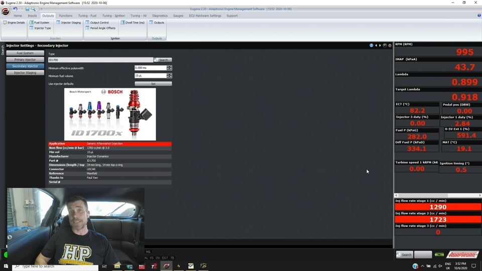
| 11:58 | Alright so then we go into our injectors. |
| 12:01 | So if we come over here we've got our injector setup, we've got primary and secondary. |
| 12:06 | Let's start with our primary injector. |
| 12:08 | So in this case we are using a set of ID 1300X injectors. |
| 12:13 | So if we are choosing from one of their pre defined injectors in this list, it's going to be really easy because Adaptronic have flow tested all of the injectors and done all of the hard work for us so it's just a case of scrolling through that list, finding your injector and choosing that. |
| 12:32 | Alternatively you're going to have to actually contact Adaptronic and see if they will provide data for your particular injectors there. |
| 12:43 | So once you've selected the injector, if you just simply click set, that's going to set all of that data for you and you can see the information down here on that particular injector. |
| 12:55 | So really straightforward there. |
| 12:57 | The next setup of course, exactly the same here on our secondary, process is identical, we can see that I've selected ID1700. |
| 13:08 | So once we've got that again, that's where this information now starts to populate and we know as our differential fuel pressure changes exactly what the flow through the injector is so it's critical not just for the accuracy of your volumetric efficiency table with a VE based fuel system for the injector characterisation data to be accurate but it's also critical if we want the staged injection to work as seamlessly as it does here on the Adaptronic ECU so really important, this is one of the key areas you've got to get this right. |
| 13:42 | If you don't have the correct injector characterisation data, you're going to be facing an uphill battle trying to get good results as we move through the rest of this. |
| 13:52 | Alright so once we've got that, the next step set up here is our injector staging so let's click on injector staging here. |
| 14:01 | And we can first of all select our number of stages. |
| 14:05 | Off the top of my head, I think the Adaptronic allows us to go up to four stages. |
| 14:09 | I know for example Andy from Adaptronic's done quite a lot of development on the Mazda RX8 which runs, some of the RX8s run three stages of injection in stock trim. |
| 14:21 | So basically once the strategy's written, it's no real chore to add additional stages, provided you've got sufficient injector outputs to control them. |
| 14:33 | In our case, really easy though, we are of course only running two stages there. |
| 14:39 | Then we've got this setting here which is pretty important to understand. |
| 14:43 | As it says here, minimum off time for stage one in milliseconds. |
| 14:48 | If you've got multiple stages then you'll have this for stage two etc as well. |
| 14:53 | So basically what this is doing is defining what the minimum amount of time the injector must be turned off for before it can be turned back on. |
| 15:01 | So in a round about way, this is kind of setting our maximum injector duty cycle that the injector will run. |
| 15:10 | So two milliseconds is their default recommendation for this. |
| 15:15 | Now the problem with this, or the idiosyncracy I guess here is that this isn't specifically injector duty cycle because the actual injector duty cycle that we'll end up with becomes a function of this off time as well as our engine RPM. |
| 15:33 | So a really good little trick here for a four stroke engine, so not really our rotary here but if we bring up our calculator here, and we don't probably want that on programmer for this to work. |
| 15:47 | If we take our engine RPM we can work out really quickly using a simple calculation, what the cycle time is or in other words, how long a full engine cycle takes. |
| 15:58 | So if we take the number 120, so that's just a constant in this, and then divide it by our engine RPM, so let's say we're operating at 6000 RPM, that gives us our cycle time which is 0.02 of a second which is 20 milliseconds. |
| 16:11 | So if we know we're at 6000 RPM and we know that the cycle time's 20 milliseconds, in this case that would give us a cycle time available of 18 milliseconds so because remember our off time is two so 20 minus two gives us 18, divided that by 20, that gives us a maximum duty cycle of 90% so just a little calculation that is really helpful to keep in the back of you mind. |
| 16:37 | For a four stroke engine, 120 divide by your engine RPM will give you your cycle time. |
| 16:42 | So anyway, for our purposes we're going to leave this as it is. |
| 16:46 | If you really want to drive the things as hard as you can, maybe up to maybe 85-90% injector duty cycle depending on your RPM, again you may want to tweak that a little bit. |
| 16:58 | If you drop it down too far, you're probably going to end up with your injector duty cycle being a little bit excessive. |
| 17:04 | I still, even with a modern EV14 style injector like to keep my injector duty cycle down below 90% where possible. |
| 17:11 | So once we've done this, everything now basically is going to work automatically, it's completely seamless and doesn't require any work from the tuner which is a little bit weird if you've come from another type of ECU which runs staged injection. |
| 17:27 | So we do have our staged injection map here so let's click on that. |
| 17:33 | And not a lot to say, it's full of zeros. |
| 17:37 | So we've got our conventional load axis of inlet manifold pressure versus RPM. |
| 17:43 | Actually back on that other page we can also set that load axis, so if you're running individual throttle bodies or something we'd probably want to have that set up as throttle position, not manifold pressure. |
| 17:54 | So zeroes, so what this does basically is defines what percentage of the fuel is going to be delivered through the primary and what percentage is going to be delivered through the secondary injectors. |
| 18:06 | For our purposes where we are running an engine where basically we want to use the staged injection strategy to deliver as much fuel as we can, this is the recommended strategy, leave this table well alone and the Adaptronic ECU is going to do all of the heavy lifting in the background for you and basically what it'll do is run the primary injector as hard as it can up to the point where it gets to that two millisecond off time limit. |
| 18:31 | When it gets there, as the fuel demands for the engine still continue to increase, it's then going to automatically stage in the secondary injectors. |
| 18:40 | And it just happens all automatically in the background, we don't need to do anything else. |
| 18:46 | However that might not be the only way you want to run this, let's say we've got that other strategy where we're running a naturally aspirated engine and we're using injectors mounted outside of the inlet trumpets for better atomisation, more homogenous mixture so what we can do here, obviously we'd be naturally aspirated, this would be throttle position, not manifold pressure but let's just say down here is our 100% throttle zones and what we can do here is let's say above 5000 RPM and above, let's say that's 80% throttle, we want to set that to 100%. |
| 19:23 | That's then going to allow us to control the staging in and out. |
| 19:27 | Now the reality is we're probably not going to go from zero to 100% staging just like that. |
| 19:34 | The reality would be that we'd actually bring in the secondaries a little bit more slowly and evenly and we'd stage out the primaries. |
| 19:43 | So here a number of zero means we're running completely on the primaries and a number of 100 means we're completely on the secondaries and 50% obviously exactly in the middle so not a lot of work to do there, not exactly too difficult to figure out. |
| 19:58 | But again for our purposes, we're going to leave this exactly as it is and what we're going to do is a quick run here on our dyno, just see how well this all works out. |
| 20:07 | After the run here on the dyno, we are going to move into questions so this is a good time to remind you, if you've got questions, please ask those now. |
| 20:16 | So let's head across to our dyno screen and what you're going to see here on the dyno screen is at the top we've got our inlet manifold pressure, so this is in kPa, you can see we've got a reference line in there at 200 kPa, around about that 14-15 psi mark. |
| 20:34 | So that's about our boost target there. |
| 20:37 | Let's also just start our logging while I'm doing this. |
| 20:43 | And then the next graph down is our lambda target so what you're going to see is at the start of the run where we don't have very much boost we'll be targeting around about 0.95 lambda. |
| 20:56 | As we move into positive boost, we're about 3500 RPM and above, we'll be down at around about 0.75, 0.74 lambda. |
| 21:05 | So enough talking, let's get a ramp run out of the way here. |
| 21:23 | Alright so there's our ramp run complete, we'll just stop our logger so we can have a look at that logging, we'll let our dyno come back to a stop and 406 horsepower at the wheels. |
| 21:35 | We can see that our air/fuel ratio is under control really nicely. |
| 21:39 | I've got a little bit of a dip here, this is actually well before the staging comes in. |
| 21:43 | We'll have a look at our staging shortly but what you can see is basically from about 3500 RPM where we are on full boost, also big props here to the Borgwarner 8474 turbocharger, really impressive that it is all in by about 3400 RPM, 3500 RPM yet is delivering in this case 406 horsepower at the wheels on such low boost, only 15 psi. |
| 22:08 | Pretty impressive setup for a 13B engine. |
| 22:12 | But what we can see is our air/fuel ratio essentially sits rock solid on our target line there of 0.75, not really doing anything too crazy. |
| 22:22 | Alright so let's have a quick look back through this. |
| 22:27 | What I'll do, I think I've actually got a log file loaded up here. |
| 22:31 | I'm not a massive fan of the Adaptronic log viewer. |
| 22:36 | It is a little bit clunky to get you head around but what we've got here is a couple of pieces of data that show what's going on here. |
| 22:46 | So our green line here that you can see understandably, that's not going to let me draw on it for some reason, that's interesting. |
| 22:54 | The green line here is our RPM, the purple line here is our lambda, we've got our yellow line here is our boost. |
| 23:01 | So that's just showing the key parameters which we've already seen up on our dyno screen. |
| 23:05 | The blue line here is our primary injector duty cycle so we can see our primary injector duty cycle comes up, the reference at the top of this is 10 milliseconds. |
| 23:15 | So we can see it comes up to this point here which we are coming through at about 5000 RPM. |
| 23:21 | We'll look across our green line here for RPM, we're at about 5000. |
| 23:26 | And we can see our secondary injectors, it's using the same scaling there as well, secondary injector starts operating and our secondary injector gets up to around about 3.5, four milliseconds by the end of the ramp run. |
| 23:40 | So right through that area, again if we look at our pink line here which is our lambda, we can see that as that staging occurs which is through this area here, where I've got my cursor, there is literally zero change to our lambda. |
| 23:55 | It tracks absolutely perfectly rock solid so it really is quite amazing how well that works. |
| 24:01 | Let's head back into Eugene here and what I tend to use when I'm just doing tuning is the log playback, it's not as nice but it's quicker and it's easier in a lot of ways so log playback basically puts the ECU into a mode where all of the data that we're seeing, the likes of over here on the right hand side, all of this data is what we were seeing during the ramp run. |
| 24:28 | So if we get into our ramp run here, this is right where we start, so 1500 RPM, we've got about 10 kPa of positive boost, our lambda versus our target we can see we're pretty much smack bang on that. |
| 24:41 | We can also see our injector duty cycle for our primary injector there, 10% duty cycle and of course our secondaries are completely disabled at this point. |
| 24:52 | So if I cycle through here, we'll sort of get to a point where we're starting to come up in the boost and at this point, 3800, 3900 RPM, we can see that we're now up to about 60% injector duty cycle there. |
| 25:08 | Again, tracking pretty close to our target, just very slightly richer than that. |
| 25:13 | And we come through again, just want to get to a point basically where the secondaries start to stage in. |
| 25:20 | So we hit 80% duty cycle at this point, at 4800 RPM. |
| 25:23 | There we go, 83% injector duty cycle, that's the maximum we've got at that point and we can see that we've now brought in our secondaries, 13% injector duty cycle there and if we scroll through here we can see and this is sort of a factor of what I was talking about, as our RPM increases, that two millisecond off time starts to end up seeing our injector duty cycle for our primaries drop down, so we can see that now we're actually down, let's just get back to peak RPM, probably something a little bit more sensible. |
| 25:57 | We've dropped down to about 76% injector duty cycle so you do need to keep that in mind, you may need to manipulate the injector off time value a little bit if you are running right on the absolute edge of your fuel system and you do need every, basically every percentage of duty cycle that your injectors have available otherwise you're sort of going to be artificially limiting yourself at higher RPM. |
| 26:21 | Alright with our demonstration out of the way there, hopefully everyone's understood that and it's made a lot of sense, we'll head into our questions now and we'll see what we've got there. |
| 26:39 | Alright so, OK our first question here comes from Jordan who's asked, are you using the fuel film model for throttle tip in, if so was it easy to set up? Actually at this stage Jordan, no I'm not. |
| 26:55 | The fuel film model, so for those who don't understand what that term means, it's a different way of modelling what's actually happening inside of the engine in terms of the fuel puddle or fuel film that's inevitably going to end up on the port walls of the intake. |
| 27:14 | So not all of the fuel that the injector injects actually makes its way into the combustion chamber or rotor housing during the intake stroke. |
| 27:22 | Instead a portion of the fuel actually goes and makes a pool of fuel or a puddle of fuel on the port wall. |
| 27:29 | And this is the actual reason why we end up with a situation where we need tip in enrichment or acceleration enrichment and decel enleanment because what happens when we have a very rapid change in manifold pressure is the mass of fuel, the volume of fuel in that fuel puddle increases as we tip into the throttle so instead of all of the fuel that's being injected going into the cylinder, a lot of it, during that brief period will actually go to increasing the volume of fuel in the fuel film and this is why we see a lean condition. |
| 28:01 | Likewise when we tip out of the throttle and the manifold pressure drops down, the fuel puddle size decreases so we end up with an increase in the amount of fuel going into the engine because we've got the injector injecting fuel and some of the fuel from the puddle is also going into the engine so long winded answer to that but that's what fuel film modelling does and it does a better job when set up correctly, of basically modelling what's happening in the engine. |
| 28:25 | Theoretically then, giving us better control over our tip in enrichment, decel enleanment. |
| 28:30 | However there is a bit of work that goes into that. |
| 28:33 | The reason I haven't set it up right now is we just simply haven't had the time to go through that aspect of it but if you are interested in learning more, we will be doing some webinars on fuel film modelling on the Adaptronic ECU in the not too distant future. |
| 28:50 | Alright I'll leave it at that for today, we've got a couple of questions there that are a little bit off topic, I'll answer those, don't feel that you're going to miss out but I'll answer those once we've finished the webinar. |
| 29:00 | Thanks for joining us and hopefully we'll see you again in our next webinar. |
Timestamps
0:00 - Intro
0:15 - What is staged injection and when would we use it?
5:55 - Adaptronic software tour
6:35 - VE based
7:25 - Target AFR
8:50 - Fuel system settings
11:55 - Injector setup
13:50 - Injector staging
17:25 - Staged injection map
20:15 - Dyno ramp run
22:20 - Data analysis
26:35 - Questions


