258 | Introduction to Rotary Tuning
Summary
Rotary engines have a bad reputation for their reliability, however the truth is that a well built and properly tuned rotary can live a long and healthy life. The key to reliability from the tuner’s stand point however is understanding the tuning requirements are very different on a rotary engine. In this webinar we’ll cover off some of the intricacies of rotary tuning and what you need to understand.
| 00:00 | - Hey guys it's Andre from High Performance Academy here, welcome to another one of our webinars. |
| 00:05 | And today we're going to dive into the world of rotary tuning, we're going to cover some of the basics, some of the fundamentals of rotary tuning and we'll have a few live demonstrations of the aspects that I'm talking about as we go on our Mainline Pro Hub dyno. |
| 00:20 | Rotary tuning information is something that we have been asked about for just about as long as we've been in business and it's something that we've been trying to bring out which is one of the reasons why we purchased and built up this FD RX7 project. |
| 00:35 | It sort of coincides with that launch of a full worked example using the FD RX7 on the Adaptronic Modular Series ECU. |
| 00:44 | If you do want to learn more about that and see the HPA 10 step process being applied from start to finish, that is already available in the worked example library in our Practical Standalone Tuning course. |
| 00:56 | However today we are going to still go over some of those fundamentals so if you've watched that worked example, some of this will be already covered but we're going to go into a few other aspects as well. |
| 01:07 | Interestingly, despite the fact that clearly the rotary engine works on a completely different operating principle to the piston engine, we actually find that the rotary engine in general responds in a very similar way to both fuel and ignition timing compared to a piston engine. |
| 01:25 | So that's good because everything we learn in the likes of our EFI Tuning Fundamentals and our Practical Standalone Tuning course does still apply to the rotary engine. |
| 01:32 | But of course there are some caveats and that's really what we want to focus on today. |
| 01:37 | Before we dive in too deep I just want to give you a bit of a rundown on the car itself if you don't know anything about this. |
| 01:43 | So jump across to my laptop screen and this is the angle that is a little bit difficult to show you on the webinar. |
| 01:49 | So the car itself is a low kilometre series seven RX7 and it is still fitted with the stock 13b engine. |
| 01:57 | However the areas that we've focused on are modifying the inlet airflow and outlets, so that's of course the turbo kit here. |
| 02:07 | So we are running a Borgwarner EFR 8474 turbocharger. |
| 02:12 | This is mounted to an investment cast stainless manifold from Turblown Engineering. |
| 02:17 | It's also running a Turblown exhaust system as well, so basically the entire kit was sourced from Turblown. |
| 02:24 | This is also fitted with a pair of Turbosmart external wastegates. |
| 02:29 | Bit problematic in the FD RX7 chassis because in stock form the Turblown kit has these dump into atmosphere, we can't do this road legal in New Zealand so it's quite an intricate exhaust system that plumbs those all the way to the rear of the car. |
| 02:44 | The EFR 8474 turbo, little bit difficult to see here but also incorporates a built in recirculating valve that's been swapped to a Turbosmart valve so that's the turbo side. |
| 02:56 | Now on paper, all in that turbo's probably good for somewhere between 800 and 900 horsepower. |
| 03:03 | Sufficed to say that's a long way ahead of where we intend to go with this stock low kilometre 13b and this really ties in quite nicely to one of the aspects we're going to talk about which is rotary reliability and keeping our power targets under control. |
| 03:19 | So while we are running the stock 13b we're going to be targeting around about 400 wheel horsepower at the most and that should be something we can achieve on relatively low boost pressure, somewhere in the vicinity of about 15 psi. |
| 03:32 | Some other upgrades there, horrible shot but hopefully you can sort of see what's going on. |
| 03:37 | We've got a CJ Motorsports fuel rail kit. |
| 03:40 | So that's for the primary and the secondary there. |
| 03:42 | Converts to the more common EV14 style top feed injector. |
| 03:48 | For this particular build we're using a set of ID1300 primaries and ID1700 secondaries. |
| 03:54 | One of the reasons, that's probably overkill for a 400 horsepower at the wheels build but we do want to end up running flex fuel on this. |
| 04:02 | Now in this shot here as well, little bit hidden but we have upgraded the factory waste spark ignition system to a set of individual direct spark IGN1A coils so pretty normal stuff there. |
| 04:15 | I have talked about this in a lot of our webinars before but for those who are new to it, we have also taken the opportunity to convert this particular 13b to drive by wire throttle. |
| 04:26 | Little bit unique, there are some kits on the market that allow this to be done using a GM style throttle body which mounts to an adaptor basically up in place of the stock throttle body. |
| 04:39 | I didn't want to do that because the stock 13b inlet manifold actually runs primary and secondary runners essentially with three butterflies, it's quite a unique throttle body arrangement. |
| 04:51 | And the primary and secondary butterflies are actually staggered very slightly in their opening so I wanted to retain that. |
| 04:56 | Maybe not strictly necessary but I wanted to do it anyway so we've converted to drive by wire using a BMW S54 drive by wire motor. |
| 05:04 | That is mounted down here so you can see that little push rod, down here on the air conditioning bracket. |
| 05:10 | So that's basically the hardware aspects, actually if we just pop back for a second, also supporting modifications there we've got a front mount or v mount I should say, intercooler and radiator setup which was hand fabricated by Vinny Fab here in New Zealand so that's basically the ins and outs of everything. |
| 05:27 | So nothing particularly extreme, particularly given that we are running the stock engine there. |
| 05:32 | In terms of the ECU, we are running the Adaptronic modular ECU with a full milspec wiring harness so that's what we've got going on there. |
| 05:43 | So let's talk for a start about rotary reliability and we hear a lot of people talk about how unreliable the rotary engine is. |
| 05:53 | Some of this is justified and some really is a little bit unfair. |
| 05:58 | I think one of the problems that I've seen in my entire career with the attitude that a lot of rotary owners have, definitely not all of them but a lot of rotary owners think that the rotary engine is simple, remember the rotary engine has less moving parts than a piston engine so we get this impression that rotary engines are simple and therefore anyone can strip apart and rebuild their rotary engine in their back shed. |
| 06:22 | Now that's not to say that that isn't the case and yes clearly there are less moving parts than a piston engine but the rotary engine still demands the same level of respect that you would apply to building any engine. |
| 06:34 | So we see a lot of people rebuilding the engine without really a good understanding of what goes into it, using sub par parts or parts that really should have been replaced and of course when you're building an engine with second hand parts that maybe aren't assembled with the precision that they should be, the end result is pretty much guaranteed. |
| 06:55 | Now this is sort of made worse because a lot of rotary tuners, or I should say a lot of tuners who are getting into rotary tuning don't understand the intricacies of rotary tuning, that's what we're going to be talking about today so don't worry, and they try and treat rotary engines the same way you would treat a piston engine. |
| 07:14 | Now news flash here, rotary engines, they're not piston engines, there are some differences and we do need to understand these and apply the right technique. |
| 07:23 | So if we do that though, we're going to end up getting good results and there is no reason why a rotary engine can't actually provide a long and healthy service life if we do understand the implications. |
| 07:35 | So as usual I should mention as well, we will have questions and answers at the end of the lesson so if there's anything that I talk about that you would like me to dive into in a bit more detail, anything else related to the topic of rotary tuning then please ask those questions in the chat and we'll jump into those at the end. |
| 07:53 | Let's start by talking about one of the biggest differences between rotary engines and piston engines which is our rotary fuel mixture targets. |
| 08:03 | So this is really important because rotary engines do tend to run richer than a comparable piston engine making the same amount of power, well we tend to need to run them richer I should say. |
| 08:16 | So let's start, what we'll do is we'll just get our engine up and running here on the dyno and we'll head over to my laptop screen and we'll have a look through the Adaptronic software. |
| 08:27 | So while today we will be focusing on the Adaptronic software, basically everything that we're going to talk about today will apply to just about any aftermarket standalone ECU that is used on a rotary engine. |
| 08:39 | So we've got the engine just up and running here, this is our main VE map or fuel map here. |
| 08:43 | It is a volumetric efficiency based ECU. |
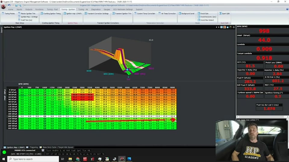
| 08:46 | While I've been talking, the lambda's come online here so I will apologise to those who prefer to work in air/fuel ratio units but today we will be working in lambda units. |
| 08:56 | So we can see that we've got our lambda sitting around about 0.90, 0.89, target there 0.92, 0.918, let's round that, 0.92. |
| 09:07 | So the first thing there is that for a stock non ported rotary, that's a reasonably rich target you would think, particularly if we've come from a piston engine background, wouldn't be uncommon for a stock piston engine to be targeting somewhere around about lambda one, stoich air/fuel ratio at idle, good fuel economy's going to come from that, good tailpipe emissions as well so let's have a look at our target lambda table here and we'll see what we've got going on here. |
| 09:36 | So we've got that graphically represented up here, numerically down below so we've got a 3D table, we've got our inlet manifold pressure on the vertical axis there and we've got our RPM on the horizontal axis. |
| 09:49 | Just to point out here, the load increases as we go from the top to the bottom of this table so our 100 kPa area here, this is actually our atmospheric pressure. |
| 10:01 | So first of all, target idle here, we can see we're at about 0.92 which is exactly what we saw there. |
| 10:09 | So we do generally find that the rotary engine is going to want to run richer at idle. |
| 10:14 | You're going to struggle to get good quality idle at lambda one, particularly if it's ported, you're most certainly going to need to be richer so that's our first consideration there. |
| 10:23 | And you can literally play with the idle mixture and see the effect of that mixture on the idle quality. |
| 10:31 | As you lean it out towards lambda one it's going to be starting to hunt, it's not going to run smoothly and it's going to start stalling so we really want to run a mixture, basically as lean as we can make it where we've still got nice smooth control of our idle. |
| 10:45 | Now we can see that we've got this chunk in the table here between about 60 kPa and zero kPa, 2500 to 3500 RPM where we are targeting lambda one. |
| 10:56 | And this is important because this is a road car so it's not a dedicated racecar, it's not going to see a lot of time on the racetrack and we want to get reasonable fuel economy so this is one of those compromises. |
| 11:10 | The problem with rotary engines is that they do tend to run hotter than a piston engine and this is affected by our air/fuel ratio targets as well. |
| 11:20 | So one of the reasons as we get into our wide open throttle full boost area, we need to be richer again. |
| 11:26 | But lambda one there, it's going to give us good fuel economy but it is going to result in higher exhaust gas temperature so I'm just going to have a quick look at that, I'll just get ourselves up and running here on the dyno. |
| 11:40 | Get our fan operating and what we'll do is we'll come up to 3000 RPM, if I don't stall it would probably be a good start. |
| 11:51 | So we'll come into 3000 RPM in cruise, so this is an area that we would be operating quite frequently at cruise so you can see, we are operating with our lambda target at lambda 1.0, we can see we're actually just a touch leaner than our target but we're a little bit heat soaked so as everything comes right we can see we're there or thereabouts, sitting at lambda one. |
| 12:11 | Interesting thing is, now it's mislabelled here but this particular parameter that I've just highlighted over on the right hand side, it says 0-5 volt external one in percent. |
| 12:22 | This is actually an exhaust gas temperature sensor so we've got one of these in each runner and we can see that while I've been talking here it's still coming up, I'm still at constant throttle, we're only at 48 kPa, we're in vacuum, I'm barely touching the throttle here, we're at about 18% pedal position and we're almost at 800°C. |
| 12:44 | So that's quite hot. |
| 12:46 | Now if we come back to that particular cell here, let's just target 0.85 lambda. |
| 12:52 | It is a VE based ECU so it might not track perfectly and it hasn't but we've gone from lambda one down to 0.9 so we're there or thereabouts again. |
| 13:03 | So we can see that our EGT has dropped, we're dropping down into the 770s now from what we were previously running. |
| 13:12 | So the first thing to understand there is our relationship between exhaust gas temperature, which is ultimately combustion chamber temperature, and our lambda. |
| 13:21 | The leaner we run the air/fuel ratio towards stoich, the hotter our combustion charge and exhaust gas temperature is going to become. |
| 13:29 | So we need to manage this and be a little bit sensible. |
| 13:31 | Now I can get away with this down in this particular area of the table here. |
| 13:36 | Because we're at such light load so we're not combusting a lot of fuel and air inside the rotary engine anyway. |
| 13:43 | And this is where we're trading off our combustion charge temperature or EGT for good fuel economy. |
| 13:50 | Really important consideration for a road engine. |
| 13:52 | Now interestingly what you will see in this VE table though, sorry this air/fuel ratio target table is once we go up above 4000 RPM, I've tapered that richer again, we're back to 0.95, if this was a race engine, I'd quite likely go even richer. |
| 14:09 | So the idea here is if we're 4000, 4500 RPM and above and we're operating in this area, generally that's going to be indicative of the fact we are in overrun. |
| 14:19 | So we're either completely off the throttle under brakes or alternatively we've closed the throttle on a gearshift. |
| 14:27 | And what I'm doing here is purposefully targeting a little bit richer than what would necessarily be required with the idea here that we're going to be passing some additional fuel through the rotor housings in order to help draw a little bit of temperature out of them. |
| 14:41 | So this can be quite beneficial, particularly for a competition race engine where it's going to be beaten on hard lap after lap. |
| 14:48 | So again we can monitor what's happening with our exhaust gas temperature and the air/fuel ratio targets we use in those overrun areas to help with this. |
| 14:56 | If you are going to use this sort of trick then obviously it should go without saying that disabling the overrun fuel cut off is going to be required otherwise when you are in those areas and you're completely off the throttle, then the injection will be disabled so again focus here is basing your decision on what you need to achieve. |
| 15:17 | Obviously if you were worried about emissions then that's not going to be a great thing which is one of the reasons why OE manufacturers tend to use deceleration fuel cut. |
| 15:30 | Alright let's go back to our table though and have a look at our other results here or our other targets. |
| 15:35 | So 100 kPa here we can see at the moment I'm running 0.90 so on a piston engine that was turbocharged, I'd probably be more likely to be 0.95 maybe even 0.98 in this area. |
| 15:47 | We're only transitioning onto boost, we don't have a lot of load, we can probably get there with no more than about 20-30% throttle so again a little bit richer. |
| 15:56 | Now for this particular engine here I am targeting a maximum boost of 200 kPa, let's call it 15 psi in round numbers so we can see this is the area we're going to be running through and I've got a nice flat across the board 0.76 lambda target. |
| 16:13 | Now again for a comparable piston engine, I'd probably more likely to be in the region there of 0.78 on the rich side, probably more likely 0.80 or thereabouts, maybe even 0.82. |
| 16:27 | So we're around about 4-5% richer at this point than what we'd run on a comparible piston engine. |
| 16:35 | As we move down further though, not that I'm expecting to get to these areas on this particular engine, we can see that we continue to move richer and for those who really can't handle lambda units, let's just have a quick look at that. |
| 16:47 | So we can see that 240 kPa, 20 psi, we're 10.9:1, then we run 10.6, 10.3. |
| 16:55 | Again I'm not expecting to need to run these air/fuel ratios because we're not in that particular boost target. |
| 17:05 | So one of the factors that we quite often hear is the air/fuel ratio targets that people tuning rotary engines are quoting are exceptionally rich and yes we do need to run a little bit richer than a piston engine but generally I err away from the side of the excessively rich mixtures that some people talk about. |
| 17:26 | I hear a lot of rotary tuners basically any turbocharged engine, that's straight away 10.5:1 or richer. |
| 17:33 | And you can see there, my target was basically just sitting on 10.9, 11:1. |
| 17:39 | What we will find is that if we richen the air/fuel ratio from there what we're going to end up finding is that we will start to see our power drop off quite dramatically. |
| 17:49 | So what we end up with is kind of a curve, it's almost like our MBT timing curve which we'll look at shortly and what we want to do is make sure that we're basically at the point where our power is just starting to drop off a little bit with our richer mixture but before we actually fall off the cliff and that's going to help control our combustion charge temperature. |
| 18:13 | Alright so that's our first aspect there, we've had a quick look at our rotary air/fuel ratios. |
| 18:18 | The next aspect that we're going to talk about here is our rotary ignition timing. |
| 18:25 | And there's a few aspects that sort of go hand in hand with our ignition timing that we need to understand. |
| 18:31 | This is probably the area where I think most people go wrong and most people do damage so the first place to start here is understanding how to set our base ignition timing. |
| 18:43 | So what we can do here, if we go to our inputs and to our triggering. |
| 18:49 | So triggering is up here, and again this is specific to the Adaptronic ECU but just important to understand what's going on here. |
| 18:56 | We have a function here called timing lock enable. |
| 19:01 | So at the moment we can see it says no timing lock and that's important because we are running a normal timing map. |
| 19:08 | If we open this up we can see, timing lock normal, we can set timing lock normal or timing lock rotary. |
| 19:14 | ...would make sense here that we use the rotary option so it's important to understand what that will do. |
| 19:22 | So If we use timing lock normal this is conventionally for piston engines and what it will do is set the timing to a fixed value of whatever our base angle is. |
| 19:33 | So we can set that up here. |
| 19:35 | With the timing lock rotary it'll set the leading to -5 and the trailing to -20 which might seem like strange numbers but there is a method to Adaptronic's reasoning behind that so if we just...this is the timing pulley on the front of the FD RX7 or 13b-REW engine and so it's a crank trigger system. |
| 20:02 | We can see here here there is a little divet in the pulley and that's our timing mark and that coincides with this mark that is on the front cover of the engine. |
| 20:15 | When those line up, the timing there is -20° so 20° after TDC. |
| 20:22 | So remember the timing, the rotary timing mode for the Adaptronic sets the leading at -5 and the trailing at -20 so if we're doing a series 6, 7, 8 engine with that timing mode, if we time off the trailing, then we should see this little mark here coincide with this little guy here. |
| 20:42 | That should mean that our timing is correct. |
| 20:45 | On the other hand if you just let me get back to my notes for one second here I'll find the other aspect that I wanted to show you. |
| 20:53 | Right if we go across to my laptop screen, on the earlier rotary engines, there were two timing marks on the pulley and a single pin so the timing marks here, there was a mark at 5° after top dead centre which was a yellow mark and there was a second mark at 20° after TDC which is the red mark. |
| 21:14 | So it's really important, probably this is rule number one or rotary engine tuning, setting the base timing is just as critical as any engine, just as critical as a piston engine, we want to make sure that the timing that the ECU is delivering is the same as the timing, sorry that the ECU is delivering is the same as the timing that the engine is actually receiving if we have got the timing light pointing at the crank pulley. |
| 21:38 | But this requires understanding what those marks actually mean. |
| 21:42 | So it's going to depend of course there what generation of rotary engine you are tuning. |
| 21:47 | If you were on the earlier series four, five, for example with the two timing marks there, if you used the timing mode from the Adaptronic, we could go onto the leading plug, that should fire on the leading mark, the trailing plug should fire on the trailing mark because remember it sets it to -5 and -20°. |
| 22:09 | However that's a little bit tricker with the series six, series six, seven, eight so we've only got that one timing mark so remember that's going to be -20° so there's two ways we can do this. |
| 22:22 | As I mentioned, we can set the, we can time it off the trailing plug. |
| 22:28 | I like to not take any chances though, I like to check the timing on the leading and the trailing so what we can do there is use the rotary mode, time off the trailing should coincide with that mark. |
| 22:41 | Come back into our Adaptronic ECU. |
| 22:43 | If we select the timing mode as timing lock normal, we can then set a base angle that we will be able to actually see on the rotary front cover for our leading plug, so -20. |
| 22:57 | Now the thing is, the engine isn't going to run particularly happily when we are doing this so it's important here to, or it's helpful to use someone to sit there and actually manually bring the RPM up and hold the RPM up while you're actually checking that timing and making sure it's OK. |
| 23:13 | Other key thing is that once you've done that, you do want to make sure that you come back and turn your timing lock off because, I'll just go to timing lock normal here and it's going to stall so that's what we get the ability to see here is our timing lock angle, when that timing lock is set to on. |
| 23:31 | So I've got that at -20 because I was doing my leading plug. |
| 23:34 | Now once we've done that we want to come up here and if there is a discrepancy between the timing we're seeing with the timing light and the timing that the ECU is requesting, in this case -20, we're going to adjust that with our base angle value there and then again as I mentioned, turn our timing lock off. |
| 23:51 | Now not such a big deal with that particular configuration because as you saw, the engine's not going to run very happily at -20° but if you're using another value where the engine will run you're going to end up with very retarded timing values, it's going to create a lot of heat in the exhaust system, the combustion chamber and you're also going to wonder why the engine isn't actually responding to your tuning changes like you'd expect. |
| 24:15 | So that's our first aspect there, understanding what the timing marks are so that we can properly set our base ignition timing. |
| 24:23 | Now let's have a look at the timing map that we've got here and we'll come into our ignition timing map. |
| 24:29 | And in a lot of ways the numbers we see here are quite similar to a piston engine but we do want to be really mindful of the numbers we're using because too much timing can easily cause detonation in the rotary engine which is in my opinion probably the number one killer. |
| 24:47 | It's a good time to just talk about knock detection on rotary engines. |
| 24:51 | There are a lot of tuners out there who do use knock detection on rotary engines and I'm talking here about closed loop knock control with audio knock detection. |
| 25:01 | I'm not a big fan of this, the reason that I don't use it is because in order to set up and validate closed loop knock control, we need to actually make the engine knock, we need to induce some level of knock so that we can find out what the knock threshold needs to be and what the knock frequency is. |
| 25:18 | The problem with a rotary engine, particularly a stock one with stock seals is almost any level of detonation can actually damage the engine so basically what I'm saying is we're going to almost most likely end up doing damage while we're setting that up so conservative numbers here are the aim of the day and staying away from knock. |
| 25:38 | That is why I don't believe in knock control on a rotary engine. |
| 25:42 | I do typically still use audio knock detection while I am tuning the rotary engine. |
| 25:47 | Can give you a bit of a safeguard, you might get a bit of a get out of jail free card if you do hear something occurring and you can get out of the throttle quick enough but most instances the engine's going to be damaged before we really get a chance to react. |
| 26:00 | So let's have a look at the relationship here between our ignition timing and our engine torque. |
| 26:06 | It's a little bit tricky to do but let's get ourselves up and running here and we'll see if I can do a good enough job of this. |
| 26:14 | So what we'll do here is we'll bring up our torque optimisation test. |
| 26:19 | Now I am straddling a few cells here so what I'm going to do is set all of the cells there to 10°. |
| 26:28 | Now just while I'm doing this, before I get started, I just want you to watch back on my laptop screen for a moment here, hopefully I haven't thrown Luke under the bus, that with that 10° timing, you can see that our exhaust gas temperature is skyrocketing. |
| 26:40 | Still coming up 960° so I'm just going to clear this and get going and what we're going to do here is just going to advance the timing at a degree every second or thereabouts and we're going to go all the way through from 10° through to 45 and hopefully I'm going to be able to do a good enough job of staying stable on the throttle here so we can get a nice relationship between our torque and our ignition timing. |
| 27:06 | So as I'm coming up through 27° at the moment, you might not be able to see this on my laptop screen at the moment but our exhaust gas temperature has dropped, we've gone from 860 where we started, down to 820. |
| 27:18 | So come down through 32, 34, 35° now and we're going to go all the way through to 45 here. |
| 27:28 | And it's not the best graph unfortunately which is a shame but let's back off and we'll talk about it. |
| 27:37 | So first of all, if you've ever seen me do one of these for a piston engine, the general trend, the general shape of that graph, is still the same. |
| 27:46 | However what we can take away from this is that the piston engine is a little bit more sensitive to ignition timing than a rotary. |
| 27:54 | Here we've gone from let's say 110 pound foot of torque at 10° through to about 185 so we've picked up about 75 pound foot of torque. |
| 28:06 | So not insignificant don't get me wrong. |
| 28:09 | Little bit of this though, this isn't actually quite the shape I was hoping to be able to show you, very difficult to do this repeatedly and accurately because it does rely on staying so carefully in the centre of the cell which unfortunately I haven't quite done there. |
| 28:23 | So generally what we'll find is that this would have probably tapered off somewhere around about 28°, flattened off and then right at the top end we would have plateaued and fallen away. |
| 28:32 | So we've artificially just increased this, unfortunately not staying quite smack bang in the middle of the cell. |
| 28:38 | So generally what we see with the rotary engine is the shape of this curve is just a little bit flatter than a piston engine. |
| 28:44 | And what this means is that we don't want to be chasing torque and power using timing with the rotary engine like we can with the piston engine. |
| 28:54 | First of all, one it's not as necessary, we're not going to need to do that to make every last kilowatt or horsepower out of our engine because of that relationship. |
| 29:04 | And two, the rotary engine, very insensitive to knock so again I haven't drawn the best diagram here but let's say we would have plateaued generally around about 28° and we would have seen that from about 21, 22° through to about 28° we really wouldn't see much more than a couple of percent change in our power and torque and that's kind of the area that we want to be setting our timing so as we're increasing our timing and we're seeing the torque increase and then start to drop away, the increases aren't getting so big, we're only seeing maybe one or two pound foot of torque for every degree of timing. |
| 29:43 | That's the time to stop and sort of think to yourself well look it's not really responding anymore so let's be a little conservative and we'll leave ourselves just to the left of MBT, we don't want to be chasing peak timing, MBT timing like that. |
| 29:58 | Now the other aspect there is a lot of people think OK well I'm going to be super conservative on the timing and that's going to mean that my engine's going to live a long and healthy life. |
| 30:08 | Yes to a degree, sure you're probably unlikely to end up in a situation where you're going to end up with knock necessarily but what you are going to be doing is creating a huge amount more exhaust gas temperature, particularly with a turbocharged rotary engine. |
| 30:24 | That can end up damaging your exhaust components, your turbine wheel etc. |
| 30:28 | You saw there, we were only at 60 kPa, I was only at about 18 or 20% throttle and we were seeing the exhaust gas temperature skyrocket past 860°C before I started adding that timing back in so we do need to strike a happy balance here. |
| 30:45 | We don't want the timing so conservative that we're giving away a huge amount of torque and power and creating very high exhaust gas temperature. |
| 30:52 | We do need to have enough timing in there that we are bringing that exhaust gas temperature under control which is one of the reasons why where possible I do like to have exhaust gas temperature sensors on a rotary engine. |
| 31:06 | OK so we'll close down our torque optimisation test and we'll have a look at some of the other aspects for the trends in our timing table here. |
| 31:15 | So obviously we've now got this big chunk here that I've just set to 45° so let's ignore that and look at the other trends. |
| 31:23 | And again if you've seen these trends in a piston engine before, they really are very very similar. |
| 31:29 | Remembering here that we've got 200 kPa as our target. |
| 31:32 | From around about 4000, 4500 RPM where we are on full boost, the numbers that we can see here aren't too dissimilar to what I would expect on some piston engines. |
| 31:42 | 12 to 15°, what we do tend to see again with a rotary engine is as our RPM increases, we don't tend to quite see the increase in timing with that RPM so we're not going to be chasing the timing up quite as dramatically as we would with a typical piston engine. |
| 32:01 | So the two trends still exist though, as we go from low RPM to high RPM we've got less time available for the combustion event to occur so we do tend to see an increase in advance in our timing. |
| 32:14 | The other trend we've got here in this graph, let's close that down because we don't need that. |
| 32:19 | The other trend we've got in our graph here as we go from low load which is the top of the graph, to high load, the bottom of the graph where we've got high boost, we tend to see the ignition timing retard. |
| 32:30 | This is because we're now packing more fuel and air into the rotor housing. |
| 32:34 | The combustion speed physically is faster as we increase the load so again to achieve MBT or at least get our peak cylinder pressure where we want it to occur, we need to retard the timing. |
| 32:48 | So the two trends again, exactly the same as what we see in a conventional piston engine, no difference there. |
| 32:54 | The key is just being conservative with our timing. |
| 32:59 | And making sure that we are controlling our exhaust gas temperature. |
| 33:03 | Now the other intricacy though when we're talking about ignition timing with rotary engines comes down to the trailing split. |
| 33:11 | So this is an aspect which I know confuses a lot of people. |
| 33:15 | With the rotary engine there are two spark plugs per rotor housing, got the leading plug which is what is triggered off this main timing table here so this table defines when the leading plug will fire. |
| 33:28 | But then we're got a trailing plug as well. |
| 33:30 | Different ECUs handle this in a different way but the most common way is to use a spark split or trailing split table. |
| 33:37 | In the Adaptronic we can find that over here so we'll click on that. |
| 33:40 | So this is a much simpler table, much smaller with less break points but we still have the same axes, we've got inlet manifold pressure vs our engine RPM. |
| 33:51 | So this simply defines how many degrees of eccentric shaft rotation after the leading plug fires the trailing plug will fire. |
| 34:00 | And this is another area where a lot of people don't really understand what they should be trying to achieve. |
| 34:05 | I see a lot of people trying to chase power with a trailing split table and the reality is that can be quite dangerous and it's not really the place we want to be trying to find power. |
| 34:17 | What we need to understand with this table is that reducing the numbers in this table, reducing the split or basically having the trailing plug fire closer to the leading plug, has a very similar effect to overall advancing the timing so particularly under high load, this can potentially be dangerous so we want to be mindful of this. |
| 34:36 | Now the table that I've got here is one that I find works pretty well for just about every rotary engine that I tune so I don't tend to stray too far away from it. |
| 34:45 | Numbers here have sort of been reverse engineered from some basic Mazda maps as well as just seeing what works over my career. |
| 34:54 | So we've got a slight increase in the trailing split down in the idle areas, we're running 15° of split, same as factory. |
| 35:02 | In the cruise areas in vacuum we've got 10° of split so we reduce the split a little bit and then on boost I've reduced it down a little bit further to about 8° which is about as far as I'd really be comfortable with going. |
| 35:15 | The reality is thought, if you aren't comfortable with this table, you don't know what to do with it, then the safest bet is set the entire table to a value of 10°, it's not quite going to be optimal but it's going to be there or thereabouts, it's going to give you a pretty good result. |
| 35:32 | So what we'll try and do here, we'll just do another quick demonstration here just for simplicity I'll just set all of these cells that we're going to operate here back to 26° and again hopefully I'm not going to throw Luke too far under the bus with this, we'll just get into the middle of this cell here and what we want to do this time is use the little red torque graph here on our Mainline dyno. |
| 35:57 | So this is plotting our torque in real time so we can see that that red line's moving around a little bit but pretty much consistent as long as I stay in the same cell. |
| 36:07 | So what we want to do here is now come over to our rotary split. |
| 36:11 | So we can see that at the moment the rotary split there's 10°, I am interpolating a little bit. |
| 36:15 | So let's just try setting that rotary split to 15°, what I want to do, haven't pressed enter yet so that change hasn't taken place, just want to look at that red line there on our graph and trying to mentally average the small oscillations we'll see, I'll press enter. |
| 36:30 | Realistically zero difference. |
| 36:36 | Let's try advancing that so we'll go from 15° to 8° so let's just try and get back in the centre of the cell. |
| 36:43 | Can see that the numbers just skyrocketed there but we'll just wait for that to get consistent. |
| 36:49 | And it's not very consistent, there we go, I'll press enter and again we see essentially no change there so the trailing plug is not there so much as a power plug, it's not about the power it's about completing what's left of the combustion process. |
| 37:06 | Theory goes here that 95% of the combustion process is completed by the leading plug, the trailing plug is there to just finish off what's left of that combustion. |
| 37:17 | Yes there can be some power in this, it's also an emissions consideration there as well so those are the factors there that we need to consider with our trailing plug, don't go chasing power with that, be mindful of reducing the numbers too far. |
| 37:31 | If in doubt an across the board value of 10° is going to be safe. |
| 37:36 | Alright we're going to move into questions really shortly so if you have any questions, I can see we've already got a bunch of them there, if you've got any more, please keep them coming. |
| 37:47 | The last demonstration I want to do or the last thing I want to talk about here is staged injection, because this is another peculiar aspect to the rotary engine. |
| 37:55 | Now yes staged injection of course does exist on piston engines but it's a little bit less common, definitely your garden variety piston engine off the showroom floor is unlikely to have staged injection whereas the rotary engine is guaranteed to have staged injection. |
| 38:12 | So why do we have this? Well it's about the fact that we've got less time available to get the fuel injected, plus we've got two rotors so if we had one injector per rotor housing, that's going to make it even more difficult to have an injector that's sized sufficiently to keep the engine happy under high RPM, high load but still give good idle quality. |
| 38:34 | So let's just jump back into the software here for a moment and what we'll do is we'll start by coming across to our fuel system and our injector type. |
| 38:42 | So here we've got our primary and our secondary injectors that we can define. |
| 38:48 | Here we've got an ID Injector Dynamics 1300 cc primary injector and for a secondary injector, ID1700 as well. |
| 38:59 | You can choose most of these from a drop down menu, making your life a little bit easier. |
| 39:03 | This just gives full characterisation data to the ECU of those injectors. |
| 39:07 | That's really important for the volumetric efficiency based fuel model to work properly as well as the staged injection so this really becomes a bit of a case of garbage in, garbage out, if you can't give good quality data around the injectors, you're likely to find that the staged injection as well as the rest of the fuel model isn't going to work properly or at least not as well as it can do. |
| 39:33 | Alright so once we've got our staged injection, our injector setup done, we'll come back over here and we've got our main fuel map which we've already looked at. |
| 39:43 | We've got our injector staging out here so let's have a quick look at that. |
| 39:47 | So injector staging there, in the Adaptronic, of all of their ECUs that I've used over the years I think it's fair to say that the Adaptronic probably does the most seamless job of staged injection which is great from our perspective 'cause it leaves us with very little work to do. |
| 40:06 | But let's go over it so what we've got here is the number of stages of injection that are available so we've obviously got two here. |
| 40:12 | Off the top of my head I think the Adaptronic can do up to four stages of injection, provided you've got sufficient injector drives so suitable obviously for very high power rotary drag engines for example. |
| 40:24 | And then the other key parameter we've got available here is the minimum off time for stage one. |
| 40:31 | Now this is an around about way of essentially defining what the maximum duty cycle for the stage one injectors will be. |
| 40:38 | Now it's not quite injector duty cycle because this defines, as its name implies, the amount of time that the primary injector must be off before it can switch on for its next injection cycle. |
| 40:49 | So of course two milliseconds off time becomes a variable target in terms of injector duty cycle depending on the RPM that that's occurring at but we find with this, I think off the top of my head it hit about 90% injector duty cycle and as the RPM increases, it sort of drops back a little bit so we're probably there or there abouts of what I'd want to run. |
| 41:11 | OK so that's as simple as it is and basically for a turbocharged rotary engine where our aim is to get as much fuel into the engine as we need, it's all we need to do. |
| 41:22 | The other aspect we've got the ability to adjust here is our two stage injection map, so we'll have a look at this. |
| 41:30 | Not a lot to see as we can see here, we've got a 3D table, inlet manifold pressure vs RPM. |
| 41:36 | Numbers in this table though are all set to zero so pretty simple there. |
| 41:40 | Numbers in this table basically define what percentage of the fuel will be delivered through the secondary injectors so numbers of zero here mean that all of the fuel will be delivered through the primary injectors. |
| 41:52 | If we leave this table like it is set up now though, what is going to happen is that the Adaptronic ECU is just going to automatically run the primary injectors as hard as they can, or as hard as it can up to the point where it hits the two millisecond off time limit and once it gets to that point then it's going to start gradually and smoothly staging in the secondary injectors. |
| 42:15 | So from our perspective again, no work to do, it all happens automatically in the background and it's really really nice and seamless. |
| 42:21 | On the other hand you may want to use this map in a different way, it may be that you want to, maybe you're running an engine where you've got hi/lo injection with injectors fitted down near the inlet valve on a piston engine and another set out of the inlet trumpets which you want to stage 100% onto at high RPM. |
| 42:40 | Well then you can start manipulating the numbers in this table to achieve exactly what you want but for our purposes, really seamless. |
| 42:47 | So what we'll do here is we'll just have a quick dyno run so that we can see how this all works. |
| 42:56 | Now I have been having some trouble as well, I will apologise with our CAN bus on this car at high RPM is giving some very weird data for our lambda so you're probably going to see that our lambda trace actually isn't going to be that smooth and nice during this ramp run but let's head across to the dyno screen. |
| 43:14 | On the top you're going to see inlet manifold pressure, got a reference line in there at 200 kPa or 15 psi, we've got our lambda plot in the middle, as I say expect to see that look a little bit erratic. |
| 43:25 | Target in there at 0.78 and then of course our power down the bottom so let's get a run underway and we'll have a look at what our injection's doing after this run. |
| 43:51 | Yeah as I expected, doesn't look that pretty but I can guarantee you that my lambda is a little bit more on target than that. |
| 43:58 | So 385 horsepower for that particular run. |
| 44:02 | So what we'll do, we'll go into our laptop software again and we'll have a quick look here in our log viewer. |
| 44:09 | This is not my favourite feature of the Adaptronic ECU. |
| 44:12 | I find it a little bit clunky to use and am I actually going to be able to see this data? No maybe not. |
| 44:25 | That's not particularly helpful. |
| 44:30 | Alright without spending a little bit more time manipulating this I don't think I'm actually going to be able to show you what I wanted which was the injector duration for our primary and secondary but it's probably not going to help as well because my air/fuel ratio plot data on the ECU is going to look just as ugly so you're going to have to take my word for it. |
| 44:52 | Basically what I wanted to show you here was a datalog where we can see the primary injector duty cycle coming up or in this case injection pulse width will come up and it hits the point where it maxes out and then it drops away and we see that secondary duty cycle, secondary injector pulse width come in and we would see over that course, absolutely no change in our lambda, it's basically completely seamless so you can't really see if we're just looking at the lambda plot, any discrepancy in the lambda that actually indicates that the secondary injection is working, as I say just seamless so unfortunately not the best demonstration there but I do apologise. |
| 45:32 | Normally what I do, because I'm not a big fan of the Adaptronic logger software, I do export this into a .CSV and then analyse it in MegaLogViewer, I find that a much quicker and more effective way of analysing the log files but I'm not going to do that right here but you'll have to take my word for it. |
| 45:50 | Anyway, that brings us to the end of our lesson there so hopefully that's debunked a few of those myths or misconceptions that you may have had with rotary engine tuning, for now we'll get into our questions and remember if you've got any more, please keep asking them. |
| 46:17 | SpeedNess has asked, would be good if I could share the choice of sensors, part numbers and manufacturers on the HPA Rx7. |
| 46:24 | The component list provided under the club level wiring course is outdated when compared to the current state of the HPA Rx7. |
| 46:29 | Yeah you're probably dead right there, things did move on a little bit from when this was fitted with that club level harness. |
| 46:40 | Probably not much point sitting here spouting off part and numbers here but what I might do after this is put a post in our forum that you can have a look at there which will explain everything, there's nothing particularly out of the ordinary that we're using on here, just the usual parts that you'd expect in terms of pressure sensors etc. |
| 46:58 | Brendan has asked, I guess this might be a good time to ask, compared to piston engines and how you can't reuse head gaskets, bolts and stuff, how are rotaries when it comes to reusability of seals, tension bolts etc? Good question Brendan, I don't build rotary engines, that is one thing I have not delved into as yet so I can't really speak for those as such. |
| 47:20 | I do know a number of people who do build rotary engines and seals, for the likes of the side seals, etc, o rings etc I should say, those generally you would replace when you rebuild the engine. |
| 47:34 | Depends on the condition of other things like your apex seals and your actual side seals on the side of the rotors but again I'm not a rotary builder so probably not the best person to ask that question to. |
| 47:46 | Levyathan Magic has asked, how does porting affect idle control and powerband on turbo and NA rotaries, how does it affect part throttle as well? OK so this is a really big question because so much of it's going to depend on specifically what porting you're talking about. |
| 48:04 | There's a very big difference in different porting techniques between the likes of a mild extend port or even a bridge port compared to a peripheral port. |
| 48:15 | Peripheral port being the hardest to tune, part throttle drivability and control on a peripheral port is basically diabolical, the overlap is so dramatic. |
| 48:25 | So basically the peripheral port is really only useful at high RPM and wide open throttle or that's where it's really comes to life, wouldn't say it's only useful but that's where it really sort of comes into its own. |
| 48:39 | Basically any porting is going to require a higher target idle speed and generally because of the overlap as well, you're not getting a true indication of the actual air/fuel ratio reading so it's a little difficult to give a specific target air/fuel ratio and this is one of the areas much like tuning the non ported rotary like ours here, it's a case of choosing a target air/fuel ratio or displayed air/fuel ratio that's going to give good idle manners so it's a case of just experimenting there and you want to run on the leanest range of the air/fuel ratios being demonstrated where the idle quality is good. |
| 49:17 | So sorry it's not probably a very all encompassing answer there but there are just so many variations in between. |
| 49:24 | Ed has asked, can you please explain injection angle on a rotary and the effects of it? So yeah very similar to fuel injection angle on a piston engine, it's about trying to time the injection pulse so that we can take the best use of that way the fuel is being injected and being delivered. |
| 49:45 | So it's probably actually easier to talk about in terms of piston engine because we talked there about open valve and closed valve injection. |
| 49:54 | It's kind of similar with a rotary engine but it's open port and closed port injection. |
| 49:58 | Basically what's going to happen when the fuel is injected is it going straight into the rotor housing or is it going to have to wait for the next engine cycle? On face value you might think that timing the injection to occur when the port is open would make the most sense. |
| 50:13 | And in some instances you can find your results better when you do that however what you're then doing is relying on that atomisation of the fuel to allow it to be combusted easily and while on face value you might think that the fuel atomisation is great, it actually pales into insignificance compared to if we inject against a hot intake runner wall, the fuel is going to actually essentially vaporise off that hot wall and then it's going to be ingested in a vapour form which is much easier to burn so sometimes closed valve injection actually gets you better results, it's a case of experimenting to see how the particular engine actually performs. |
| 50:53 | What we're looking for essentially is either a change in torque as we vary our injection timing or more often what we'll actually find is that as we change our injection timing, the fuel is being introduced, the same amount of fuel but it's in a form that's easier to combust so we actually see air/fuel ratio move richer meaning that we can then remove values from our VE table meaning that we get an economy benefit as well so the numbers that I am actually running in our engine are very close to stock 13b timing values. |
| 51:29 | Joey has asked, how does one differ the idle tuning or wide open throttle from a streetport to a bridgeport, OK so basically answered that question there so we're going to need to increase our idle speed appropriately. |
| 51:43 | So this being a stock engine I'm idling at about 950 to 1000 RPM. |
| 51:47 | On a decent sized bridgeport, probably going to want to idle that engine around about 1500 to even 1800 RPM. |
| 51:54 | Rustyrotors has asked, can you demonstrate power difference with trailing ignition disabled? No I can't easily here, but it is a good test. |
| 52:07 | The test that we do there, with a rotary engine in particular because you've got the two spark plugs per rotor housing, it can be a little bit difficult sometimes to actually pick up a misfire so a good test there is to disable the trailing plug and if you've got your leading/firing you're probably going to find that your power will only drop off marginally as I mentioned, most of the combustion process does get ignited off or lit off by the leading plug. |
| 52:35 | You're only going to see a small discrepancy by disabling the trailing plug. |
| 52:39 | AX75 has asked, I thought -20 was trailing? So -20 is trailing, I'm not sure if you're getting confused there so the timing that the Adaptronic produces in the rotary mode will be -5 on the leading, -20 on the trailing but because we only have the -20 mark on the FD RX7 there is only one mark, it is at -20 which means we can only check the timing properly on the trailing. |
| 53:09 | Again I'm not 100% sure if that was the angle of your question there. |
| 53:12 | On the earlier we have two marks, one for leading at -5, one for trailing at -20. |
| 53:19 | MindBl0ck has asked, at wide open throttle what's the max EGT to be safe? I was thinking 1250 F/676 C. |
| 53:31 | So no on a rotary engine you're going to be much much hotter than that. |
| 53:37 | Rotary engines in general are going to be hotter anyway, would be, on a turbocharged rotary engine, you're likely to be seeing EGTs easily in the range of 900°C. |
| 53:48 | So I try and cap it out there, sometimes we are going to end up seeing it exceed that depends of course on how much power you are producing, how much boost you are running as well. |
| 53:59 | 670 to 700°C, that'd be pretty conservative even for a turbocharged piston engine to be honest. |
| 54:08 | SpeedNess has asked, I've calculated I need around 7200 cc of fuel for my power goals on my FD Rx7 on E85. |
| 54:15 | Based on this Im looking at a a pair of ID 1050 primaries and pair of ID2600 secondaries. |
| 54:21 | Any drawbacks tuning wise, keeping in mind I'm running smaller primaries and larger secondaries? Not really, I mean the staging really comes into this as well but the way the Adaptronic works and obviously I have no idea what ECU you're running. |
| 54:35 | The Adaptronic works really well because it's running the primaries out as hard as it can before it starts bringing in the secondaries. |
| 54:41 | So you can get a problem if you've got a really big difference between the primary size and the secondary injector size where as you stage in the secondaries you're sort of running right down on the minimum pulse with that the secondaries can run and that can give you problems with fuel control. |
| 54:57 | I would imagine, as long as you're careful with your injector staging if you're not using the Adaptronic that shouldn't be a problem. |
| 55:05 | We've seen of course some pretty big advances in injector quality these days and what we can get away with with the injectors that are on the market these days, very very different to what we could have done with the technology that was available 10 years ago. |
| 55:21 | That being said, I have not personally used the ID2600s so I can't speak from experience. |
| 55:28 | We've got a few questions here on fuel changes, AFR and timing targets. |
| 55:33 | Knock Limited on Jägermeister's asked, if you premix your fuel, will changes in premix to gas ratio from tank to tank affect the tune? Certainly not if you're within at least a moderate realm of being accurate with your premix. |
| 55:47 | I mean on this we are running 150 mL of premix per 20 L so you're going to have to make a significant change to your premix values in order to really affect the fuelling so this really just comes down to being accurate with your premix though, you wan to make sure that you stay on your target premix anyway. |
| 56:06 | AX75F92, probably the most complex name here today to say easily, thanks for that, has asked, when we transition to E85 how will your AFR and timing targets change? OK so I don't really chase power with the timing on E85, while on E85 we will be much less knock prone, we're probably going to be finding that a couple more degrees would be ab out as much as I would use. |
| 56:34 | If I want more power, I'd be chasing that with a little bit more boost rather than timing. |
| 56:38 | On E85, because of the cooling nature of the fuel as well as the higher effective octane rating, if anything we can target a little bit leaner than what we'd run on pump gas, we simply don't need to rely on the rich fuel targets in order to keep the engine happy. |
| 56:55 | So I wouldn't be uncomfortable running a little bit leaner on E85 but I'd only be marginally leaner. |
| 57:03 | Ed has asked, how much more timing would you add when moving to a fuel like methanol? Good question there, back in my earlier days I did tune quite a number of methanol drag engines and it's not like a piston engine. |
| 57:15 | Again the rotary engine, much less sensitive to timing with its power. |
| 57:19 | So there what I would tend to do, probably find that the engine is basically going to tell you what it wants but you'll probably find that the engine won't actually want a significant increase in timing moving from pump gas to methanol. |
| 57:35 | Some of that timing change does come from the fact that methanol is a slower burning fuel but again, really one of the changes, one of the reasons we go to methanol is to support much more boost and that's where our power's going to come from. |
| 57:49 | Cody has asked, if you had to choose, rotary or piston? Well I did and we chose both. |
| 57:59 | Right I think I'm going to leave it there because we've probably got a couple of questions there that are starting to get a little bit off target there, I don't want to go too long either so we'll leave it there for today. |
| 58:10 | Now if you are watching this in our archive after the webinar has aired for our HPA members, if you do have any questions on this webinar, please feel free to ask those questions in the forum and I'll be happy to answer them there. |


