260 | Checking Piston-To-Valve Clearance
Summary
Ensuring you have sufficient clearance between the valves and the piston is critical to the reliability of any modified engine. In this webinar we’ll look at a simple and cost effective method to check exactly how much clearance you have.
| 00:00 | - Hey team, Andre from High Performance Academy here, welcome along to another one of our webinars and this time we're going to be delving into the topic of piston to valve clearance. |
| 00:09 | Obviously an engine building webinar. |
| 00:11 | And this is something that is really important to consider if you are adding aftermarket cams to an existing build. |
| 00:19 | So obviously the piston valve pockets that we have cut out into the crown of our piston, these are designed in stock form around the valve lift and duration that we're going to see with a stock camshaft. |
| 00:31 | Of course when we step up to a larger more aggressive cam we're getting the performance gain from that camshaft by increasing the valve lift and also increasing the valve duration or the amount of time that the valve is open. |
| 00:45 | And in some instances this can give us problems with valve to piston or even valve to valve contact depending on our cam timing. |
| 00:53 | This is also a consideration if we are going to an oversize valve, although usually that is less of a consideration, we are sticking with a stock valve seat then it's difficult to move to a valve diameter of much more than about 1 mm larger than stock. |
| 01:09 | So we're going to go through this topic in detail. |
| 01:11 | It's a little difficult to do a full live demonstration but we've got our Honda B18C out behind me that I'm going to show you a few tricks and tips on. |
| 01:19 | As usual if you've got any questions, please ask those in the chat and we'll jump into those at the end. |
| 01:26 | Right so when are we going to have problems with contact? Basically when can we expect in the engine cycle valve to piston contact? So probably important to start with a bit of an understanding of what's actually going on as we go through the engine cycle. |
| 01:43 | I understand we've got a little bit of lag with my laptop so hopefully this isn't going to play up too much but we've got a diagram here showing our full engine cycle and again, basic four stroke principle here, we've got 720° of crankshaft rotation for a complete engine cycle. |
| 02:00 | So what we've got here is our locations in the engine cycle. |
| 02:06 | We start with the piston at top dead centre or TDC. |
| 02:10 | And in this instance we're starting just after the combustion event has begun so our first stroke as we can see here is our power stroke. |
| 02:18 | Now as the piston is forced down towards the bottom of the cylinder which is BDC, labelled here, we find that our exhaust valve is going to open a little bit before the piston actually reaches the bottom of the stroke. |
| 02:32 | And if you are new to engine building and cam operating principles it might be fair to assume that the exhaust valve opens at the bottom of the stroke and then it closes at the top of the stroke, well that's not actually the case. |
| 02:45 | We can see here, probably a little bit exaggerated, it doesn't open halfway down the stroke but we do end up with our valve opening before the piston reaches bottom dead centre. |
| 02:55 | The reason for this is we want to take advantage of the blow down where we can open the valve and we can evacuate the additional built up pressure that we've still got from the combustion process. |
| 03:07 | This is a bit of a fine line or a balancing act because obviously we are using that pressure acting down on the top of the piston to generate torque of the crankshaft. |
| 03:15 | But if we were to leave the valve opening until the piston had reached bottom dead centre we're going to end up with a period of time that it takes for the valve to reach full lift, doesn't instantly jump wide open and during that time we're going to end up with pressure building up with the exhaust gas still trapped inside the combustion chamber and that's going to be counter productive to our engine power. |
| 03:40 | So that's why our valve opens before the piston reaches bottom dead centre. |
| 03:45 | This however, zero issue for us in terms of valve to piston clearance, understandably the valve is at the top of the stroke, the piston at this point is near the bottom so we don't need to worry about that. |
| 03:57 | We then go through the exhaust stroke here, so this is where the piston's moving back up to top dead centre forcing out the unburned fuel and air. |
| 04:05 | Now, as we move back up towards top dead centre here, so this is where the valves are on overlap. |
| 04:13 | We'll just deal with our exhaust valve first because that's what we're still considering. |
| 04:18 | We can see, well that's what we've started talking about I should say. |
| 04:21 | We can see that the valve remains open. |
| 04:24 | Once the piston's still gone past top dead centre and begun the intake stroke. |
| 04:30 | And at the same time we've also had our intake valve open before the piston has reached top dead centre. |
| 04:38 | This is really where our considerations and concerns are around our piston to valve clearance. |
| 04:46 | Now without getting too far into the specifics of why we have this situation with the valves both being open, with our intake valve what we're trying to do here is again get the valve open so we've got airflow basically by the time the piston has started moving down from top dead centre. |
| 05:06 | It takes a while for the air to actually start moving that air column in our intake port, takes a while for that to actually start moving, the air has density, it has mass so there is also inertia associated with that. |
| 05:18 | So what we want to do is basically optimise the fill of our cylinder during the intake stroke. |
| 05:25 | Now the other reason we've got the exhaust valve open here is we can also get a scavenging effect at higher RPM where the flow of exhaust gas will actually help draw intake air into the cylinder. |
| 05:39 | This is all a balancing act and this really comes more down into our cam selection and tuning of our cam timing as opposed to the specifics of piston to valve clearance so I'm not going to go too far into that or any further into that I should say, that's really more than we need to understand for this topic. |
| 05:56 | But what we're trying to understand is where we end up with the potential for problems. |
| 06:01 | So that's for our exhaust valve, about this point somewhere around about here. |
| 06:05 | Generally within a few degrees of about 10° before top dead centre, that's where our piston is coming up towards the top of the stroke so we've got our piston coming up towards the top of the stroke and we've still got our exhaust valve is closing so basically here the piston is chasing the valve closed. |
| 06:25 | Particularly this can be problematic as well if we've got issues with valve control. |
| 06:30 | Maybe we've got a little bit of valve float and the valve is actually not contacting the rocker or whatever mechanism we are using for controlling the valve or actuating the valve. |
| 06:40 | Then we can... basically hitting the valve where it shouldn't. |
| 06:45 | So this is another consideration when it comes to our piston to valve clearance. |
| 06:49 | We can assume that the valve is perfectly going to follow the cam profile and do exactly what is expected and of course yes that is what we should be achieving but that's not always the case and particularly if we are pushing things to the limits, to very high RPM or we've got a very aggressive cam profile, maybe the valve springs aren't suited, we haven't got enough spring pressure or maybe the valve springs are getting a little bit weak, sometimes we may not end up getting complete control over those valves so that's a problem. |
| 07:19 | The other aspect for our intake valve is on the other side of TDC, around about the same point, 10° plus or minus maybe 2-5°, that's again where our intake valve is opening and basically starting to chase the piston down the bore so basically we've got the...intake valve. |
| 07:37 | So this is the area that's the concern for us and this is the area we need to worry about. |
| 07:41 | Now while we are on this diagram as well, we'll come back to this at a later point. |
| 07:47 | One of the things we want to consider is what's going to make things worse in terms of our piston to valve clearance. |
| 07:56 | So with. our exhaust valve or our exhaust cam timing, basically if we advance that cam so we move it from the left to the, sorry go the other way, if we retard that cam, so that the exhaust valve opening and closing events happen later in the engine cycle, then understandably we're going to have the valve further open at that danger point 10° before top dead centre, thereabouts. |
| 08:20 | Likewise with our intake valve, the danger there is if we're advancing the cam timing so that we are opening the cam, opening the valve sooner, that gets us closer to that danger point as well. |
| 08:33 | The reason I mention this is because one of the factors that we do quite often consider is whether or not we have the ability to move the cam timing on the dyno. |
| 08:43 | Usually what we're going to do is we're going to start by degreeing the cams accurately to the manufacturer's specifications. |
| 08:49 | But these are still only going to be some form of compromise and they should get us into the ballpark and most importantly we then know exactly where our cam is degreed. |
| 08:59 | We can know where our valve opening and closing events are. |
| 09:02 | But ultimately I'll still usually want to try swinging the cams a couple of degrees in each direction when we're on the dyno and actually see if we can pick up any improvements. |
| 09:12 | Or maybe make a compromise that's more suited to our particular application. |
| 09:16 | So it's really good to understand how much freedom we've got in doing that before we actually run into potential problems with valve to piston contact. |
| 09:26 | Next consideration here is how much valve to piston clearance do we need? And this is the million dollar question. |
| 09:35 | If you Google search that you're probably going to get as many different answers as you have factors, threads that you find about the topic. |
| 09:45 | The reason for this is it's hard to put a specific number around this because there are so many considerations that do come into this. |
| 09:53 | A few of these would be the type of valve actuation we are using. |
| 09:58 | We also want to consider whether we're using a hydraulic or a mechanical lifter. |
| 10:03 | The RPM ceiling is a massive factor in this so what could be very very safe for 6000-7000 RPM might be really playing with fire if we take that same engine and valve train and rev it out to 9000 or 10000 RPM. |
| 10:19 | Cam profile, the valve mass, and the valve springs that we are using. |
| 10:23 | So these are all factors that will play into our consideration around what the minimum safe clearance is. |
| 10:31 | General guide though, a general rule of thumb, somewhere in the region of about 80 thou clearance or about 2 mm of clearance between the valve and the piston...is deemed to be probably there or there abouts what will be safe. |
| 10:47 | Ultimately those who are building very high end competition engines will happily sacrifice some of that because they want to absolutely optimise compression ratio plus valve opening or duration so that's a risk that they take through development of that engine testing what works. |
| 11:07 | But if you don't know any better, somewhere in the region of about 80 thou, that's about what you'd want to be considering as safe. |
| 11:15 | We also need to consider radial clearance as well so when I use the term radial clearance, if we jump to our overhead shot here we've got our JE piston here with our valve pockets. |
| 11:25 | So we've got the depth of that valve cut out. |
| 11:27 | Obviously the valve is coming in at a bit of an angle to that valve pocket, something like that. |
| 11:32 | But we also have the radial cut out here, the clearance to the outside of the valve. |
| 11:38 | So we want to be mindful of that as well and again that comes into play particularly when we start putting larger diameter valves into our engines so we need to be mindful. |
| 11:49 | Generally as a real simple guide, keeping about the same radial clearance as we have clearance vertically is going to be safe. |
| 11:59 | Technically we can generally get away with a little bit less radial clearance though. |
| 12:04 | Alright so how can we go about measuring our piston to valve clearance? There are two general ways we can do this and again it's a little bit difficult for me to do a live, full live demo of this because both methods require quite a bit of time and you're probably not going to want to sit there watching me piece everything together so I'll just talk through the first option which I'm not going to demonstrate at all, which is the method of using check springs. |
| 12:33 | So what we're going to do here, there's a bit involved in this because with check springs, we need to have a degree wheel fitted to the crankshaft and what we're going to do is make sure that we've got that degree wheel zeroed so we know exactly where abouts in the engine cycle we are. |
| 12:48 | So by zero I mean we want a true top dead centre reference so we know accurately when the piston is at top dead centre. |
| 12:55 | Before we assemble the cylinder head, what we're going to do is remove the normal valve springs that we're going to be using and we want to fit what's called a check spring which is essentially just a soft spring which is going to allow us to easily depress the valve and move it by hand. |
| 13:12 | Something you're not going to be able to do with a conventional valve spring fitted. |
| 13:15 | So we're going to do a dummy assembly with our check spring and what we want to do is essentially get the engine located at about 10° before top dead centre when we're checking our exhaust, comes back to the diagram I showed you before, that's the danger area for our exhaust valve to piston contact. |
| 13:34 | We're then going to set a dial indicator up on the back of the retainer and we're going to zero that dial indicator when we are at 10° before top dead centre and then we're going to just press down on the retainer or the valve, basically force the valve open until it gently contacts the piston. |
| 13:55 | Now there's absolutely no danger of doing any damage while we are doing this. |
| 14:00 | We'll be able to easily feel when the valve contacts the piston and we don't need to use very much pressure in order to achieve this. |
| 14:08 | Once we've got the valve contacting the piston pocket we can then look at our dial indicator and that's going to show us essentially the clearance between when we zeroed it at 10° before top dead centre and when we have pressed it down to contact the piston. |
| 14:25 | So quite quick and easy to do. |
| 14:27 | It's not particularly accurate there though because we're assuming that our maximum lift or our danger point I should say, not maximum lift, is at 10° before top dead centre. |
| 14:39 | And that's generally where we're going to be pretty close to. |
| 14:44 | But of course it could be a little bit earlier, could be a little bit later depending on specifically what our cam timing is, our lift profile for the cam as well. |
| 14:53 | So generally once I've done this at 10° I'll also try it a couple of degrees advanced and a couple of degrees retarded from that as well. |
| 15:00 | And that'll give me a pretty good feel of where abouts my minimal amount of clearance is, we can confirm that and then move on. |
| 15:07 | We do the intake valve in exactly the same way, the intake valve of course this time we're going to do 10° after top dead centre. |
| 15:16 | And that's exactly the same process so we get the engine degreed to 10° after top dead centre, zero our dial indicator, press the valve open, exactly the same process, check it a couple of degrees either way and basically find the location where our valve to piston contact, clearance I should say is minimal. |
| 15:36 | So this is relatively quick and easy to do, it does require a dummy assembly, it does require us to remove the valve train or the normal valve springs that we are running. |
| 15:46 | One problem with this is it doesn't give us any real visualisation around the radial clearance and because we are using a soft check spring there can be a little bit of error built into this as well. |
| 16:00 | So for that reason, my own personal preference, I don't like using check springs like this, I like to go through the process of using playdoh or plasticine or clay on the piston crown and actually check through a full dummy assembly with the valve springs that we're going to be using and see what we've got in that way. |
| 16:20 | So that's what we're going to go through here. |
| 16:22 | So the process of doing this require us to essentially have the cylinder head off the engine to start with so that we've got access to the piston crown. |
| 16:31 | And what we're going to do is use a product basically something nice and soft that we can put onto our piston crown and then we're going to allow the valves to contact that and leave an indent in the playdoh or plasticine or whatever we're using. |
| 16:46 | So product I'm going to use here is playdoh, really just comes down to whatever you can get access to easily. |
| 16:54 | I like playdoh, reminds me of my youth. at my age I don't get to play with playdoh too much nowadays so any excuse, break it out. |
| 17:01 | So what we've got here is our piston, we'll do this on our overhead shot here. |
| 17:05 | Few little tips for success with this. |
| 17:09 | The first one is that we want to make sure that our piston crown is completely clean of any oil otherwise our playdoh is not going to stick to it. |
| 17:17 | Particularly during the engine building process we're going to end up with oil on the piston crown and if we don't get rid of that before we apply our playdoh, we're going to end up with the chance that the playdoh is just going to get pulled off the crown of the piston as soon as the valve contacts it. |
| 17:34 | So brake clean and a clean rag, really easy way of doing that. |
| 17:38 | And I've just, as I've been talking there, just pressed that playdoh into one of the valve pockets and we don't need to go crazy here, we are really only interested in what's happening right in the corner of that valve pocket. |
| 17:51 | Unless you've got a massive problem with your cam timing, that's where we're going to be looking at. |
| 17:56 | So another tip for making sure that we get the best possible results and the least chance of the playdoh being pulled out of the crown of the piston, is to basically make sure it's flat or flush with the top of the piston so that's what I've done here. |
| 18:10 | It's not actually protruding, it's just being pressed nicely into the piston, the valve pocket I should say, on the top of the piston. |
| 18:20 | Alright so that's our first point there and we're going to do this, obviously in this case it's a four valve piston, we're going to do this on all four valve pockets. |
| 18:29 | We're going to do this on number one piston and what we're going to do is then reinstall our head and basically time up the cams and go through one full engine cycle. |
| 18:39 | We don't want to leave it in there and turn it over and over and over because that just gives us more chance that that valves are going to end up pulling the playdoh out and give us basically completely useless readings so just one full revolution. |
| 18:53 | Before we do that though, the next step is we're just going to use some clean engine oil here, so this is just a mineral based oil, I always keep a little squirty can like this around when I am building engines and we're just going to apply a little bit of that oil to the top of our playdoh, so unfortunately once we've done this, you're not going to be able to keep that playdoh, you're going to be throwing that away once you're done with it. |
| 19:14 | But just a smear of oil across the top of that playdoh is going to further help ensure that our valve is not going to stick to it. |
| 19:21 | That's the number one problem when we go through this, basically we go through the not insignificant hassle of dummy assembling the engine, timing everything up, rotate it through a full engine cycle, pull the head back off the engine and find that the playdoh's actually been pulled off the crown of the piston by the valve so not particularly useful. |
| 19:42 | At the same...a little bit of a coating of oil on the playdoh, I'd also do the same to the valves as well. |
| 19:51 | There's a couple of ways we can do this, we can use our little squirty can of oil. |
| 19:55 | I've also got here a spray can of synthetic oil that does a really good job as well. |
| 20:01 | So just a light coating on the valves just being doubly sure that we're not going to end up with any problems. |
| 20:07 | But before we see what the next step is, there are a couple of other considerations we want to make here. |
| 20:14 | Now particularly if you are running an engine that uses hydraulic lifters, if you go through this process, it's not going to really give you a good indication of what's happening. |
| 20:24 | The reason for this is that the lifters, when we're just turning the engine over by hand, won't be bled up so they won't be giving you a full, or a true indication of the valve lift and duration. |
| 20:36 | So while we're doing this, what we'd want to do is install a check lifter, something that we can make up basically to give us full valve lift. |
| 20:45 | Likewise if you're running a mechanical setup, it would go without saying that we want to make sure that our valve clearance, our valve lash is set to the manufacturer's specification. |
| 20:56 | Basically again going without saying we want to make sure that our valve lift that we're seeing during this test is exactly what we're expecting when the engine is operating. |
| 21:05 | The other aspect that peculiar to our Honda B18C there, also our SR20 VVL cylinder head is that they run a switched cam profile. |
| 21:17 | Now I've cheated a little bit here, with the demo that I've just done, just for simplicity I haven't actually done this on the high lift cam profile. |
| 21:24 | But when we are doing this, if we want to get useful data then clearly we would want to be checking everything, checking our clearance on the high lift cam profile. |
| 21:33 | That high lift cam profile on a VTEC engine gives us both more valve lift as well as more valve duration so checking on the low lift profile is not going to be particularly useful. |
| 21:45 | Couple of ways of doing this, we can mechanically lock the VTEC mechanism out or alternatively for those who are working a lot with the Honda engines, there are adaptors that you can purchase that will allow you to actuate the VTEC mechanism using compressed air from a shop supply. |
| 22:02 | But just important to make sure that you are doing that. |
| 22:06 | Another consideration, before we do this is we also want to make sure that our cams are actually degreed properly. |
| 22:13 | Of course it's not going to be that useful if we put our cam wheels in on the zero mark, check our valve to piston clearance, we're happy with all of that and then we need to go and make wholesale changes to our cam degreeing to get them onto the manufacturer's cam specifications so that's a consideration where we need to make sure that our cams are actually degreed properly. |
| 22:34 | If you are running a very aggressive cam, this might be an iterative process whereby you start with more conservative cam timing, just get an eye for what the valve to piston clearance is and then start advancing or retarding the cams, obviously we've talked about which way to go to make things more dangerous for our intake versus our exhaust valve cam timing there and as we go through this, again iterative process of just checking our progress as we go and our clearance as we go. |
| 23:01 | You will however get a bit of a feel for your first measurement as to how much clearance you've got, whether you've got plenty or whether it's looking a little bit marginal already and that will be a bit of an alarm bell if you do need to make a wholesale cam timing change in the danger direction and you already know you're getting a little bit tight there. |
| 23:22 | So that's a problem. |
| 23:23 | Alright so anyway, with our Honda B18C we've gone through, we've put our playdoh on the top of our piston crown, we've reassembled the head, we've reassembled the cams, put our cam belt on, timed everything up, gently turned the engine through one full engine cycle and then it's a case of reversing the process and pulling everything apart. |
| 23:42 | So we've already seen that our playdoh does have some match marks there showing, or witness marks showing that we do have the valves contacting the playdoh which is fine, that's what we'd expect but this still doesn't really give us the full indication of how much clearance we actually have so that's where we go to our next step. |
| 24:01 | While I'm doing this, I will just mention here that we're going to move into our question and answer session in a second so if you've got any questions, this is a good time to start asking them. |
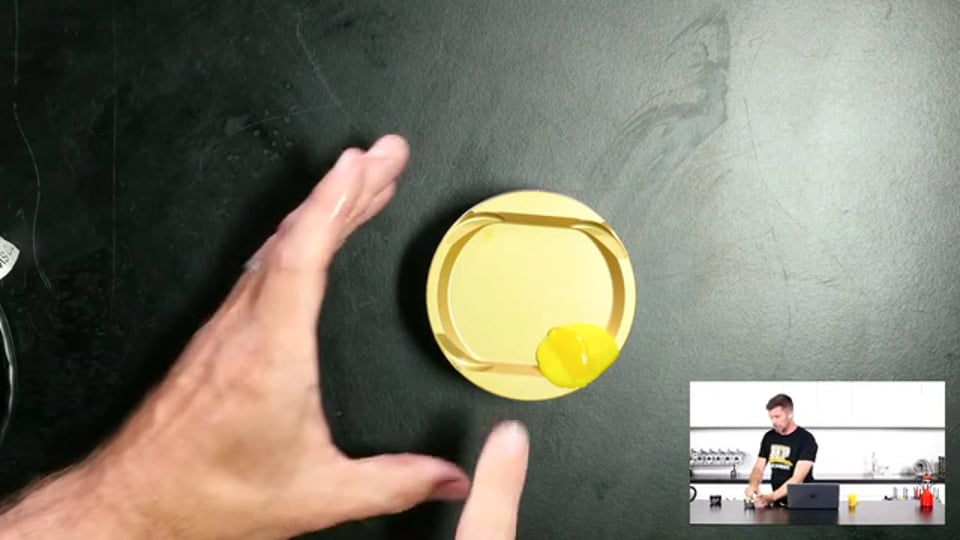
| 24:11 | Let's head across to our remote camera again, and what we're going to do here is we're going to use a razor blade to cut through the middle of our playdoh. |
| 24:22 | So I'll just get my hand out of the way so we can hopefully see this. |
| 24:26 | Normally I'll be using two hands to do this but again a little bit hard to do this without blocking the camera. |
| 24:33 | So bear with me, there we go that's actually worked pretty well. |
| 24:37 | So what we can see, yeah you can see it pretty well. |
| 24:41 | What we can see here now is a bit of a profile of the clearance between the valve and the pocket in the piston. |
| 24:49 | And this is what we're going to be using to help guide us with how much clearance we've got. |
| 24:55 | So not too sure how well this is going to come out because obviously it is quite small on our overhead camera but let's get it in there anyway. |
| 25:01 | Yeah it's probably a little bit too hard to tell but you should be able to get the idea. |
| 25:07 | First of all what we can do is look at our radial clearance which in this case is from the side of the valve pocket to the imprint. |
| 25:16 | So that's fine, in this case we've probably got about 4 maybe 5 mm. |
| 25:20 | And then we want to look at the minimal clearance, minimum clearance we've got between our indent and the underside of the valve pocket. |
| 25:27 | In this case we're probably actually pretty close to our desired minimum. |
| 25:31 | But we can get in there once we've got our plasticine or our playdoh cut like that, we can get in there with vernier callipers and actually physically measure that pretty accurately so we know where we're at. |
| 25:45 | Alright so once we know where our clearance is, the obviously question is from there, what do we do if it's wrong? Well the ideal here would be that if it is too small, we can end up having our pistons modified so most engine machinists will be able to flycut the piston crowns to increase the depth of our valve pockets. |
| 26:06 | This needs to be approached with care though because the distance between the valve pocket and the underside of the piston crown, that can end up being the thinnest part of the piston and obviously in a high powered application, we want to manage our minimum crown thickness, otherwise we end up risking damaging the piston. |
| 26:26 | So we don't want that to happen. |
| 26:28 | This is really where, in extreme circumstances you want to be working alongside your piston manufacturer to get a bit of an idea of what sort of valve lift and duration is going to be possible with a particular piston profile before you start getting into problems but in most instances you should be able to remove a small amount of material from the piston pockets without risking damage to the thickness of the crown or risking getting too thin in the piston crown. |
| 26:56 | The other option which is only going to get you out of jail so far is you can obviously manipulate the valve timing events in order to help with this. |
| 27:06 | So for example if you've got problems with your exhaust piston to valve clearance you can improve that situation a little bit by advancing the cam. |
| 27:15 | If you've got the same situation on the intake cam then of course retarding the cam can help improve that scenario. |
| 27:23 | This is going to be a compromise because of course we really want to be choosing our cam timing and our valve opening and closing events for engine performance not just to avoid piston to valve clearance but again obviously goes without saying that it doesn't really matter how optimal our cam timing is if your pistons are tapping the valves, the engine's probably not going to last too long. |
| 27:47 | Alright so we'll move into our question and answer session now. |
| 27:52 | If you do have any other questions please feel free to keep asking them. |
| 27:57 | First questions comes from CSM who's asked, are you going to touch on piston to valve clearance with hydraulic cam followers such as a Porsche 968? Porsche 968 is not an engine that I am personally familiar with but as I did mention, we do need to be mindful of a hydraulic lifter arrangement that yes it is a problem. |
| 28:16 | We do need to set that up, if you've got a hydraulic lifter arrangement irrespective of the type of engine then you are going to have to fit a check lifter or a modified lifter in place for the purposes of going through this process. |
| 28:31 | Otherwise you're simply not going to be learning anything because the stiffness of the valve spring is essentially going to just bleed down the lifter as we go through the engine cycle so you're not going to get full lift and duration from that. |
| 28:45 | Again, not specifically, I don't specifically have knowledge on that Porsche 968 engine so I can't give you much more detail on that but I haven't struck a hydraulic lifter that I haven't been able to modify in some way. |
| 29:00 | Often it'll be a case of having a couple of spare lifters that you can use for the process, either remove the internal check valves and use a mechanical spacer to get your valve lash set to zero or alternatively even if you've got a hydraulic lifter with a spring in it that will allow it to pump up and set the valve lash at zero. |
| 29:20 | Sometimes if you can get access to that lifter easily, it can be sufficient just to put a small tack of TIG weld on the lifter to lock it in place. |
| 29:31 | Important if you are doing that. |
| 29:33 | The reason I mention TIG weld rather that MIG weld, MIG will ultimately end up with some level of weld spatter which you definitely don't want inside your engine. |
| 29:43 | TIG you've got a lot more control over that and you're not going to get weld spatter so just a little common sense applies there. |
| 29:50 | Bob's asked, what about using plastigauge, this way you can measure the amount of clearance that you have since you can measure the width of the plastigauge, I believe it would be easier and more accurate? So the problem with plastigauge, plastigauge really exists to measure our bearing clearances so the problem with plastigauge, it is very very thin. |
| 30:08 | If we get to a point where plastigauge is giving us an indent or it's squashed flat, we've almost certainly got way way too insufficient clearance between our piston and our valve so I'm not sure Bob if that's what you're referencing there or if I'm missing something but I don't think plastigauge would be a product that is going to help us in that instance. |
| 30:32 | Dante has asked, wondering if valve clearance changes when the engine is hot versus cold since things expand? Yeah absolutely Dontae, they 100% do and this is where we have to basically put some sensible values in place here. |
| 30:48 | This is why we aren't aiming for minimal clearance of let's say 5 or 10 thousandths of an inch cold, that's why I mentioned the usual clearance that we're looking for, somewhere in the region of about 80 thou or 2 mm and that's there to allow first of all for some flexibility in what's going to be an actual running clearance when everything is hot, when the piston has heated up and expanded and our valves have heated up and expanded. |
| 31:14 | And also as I've already mentioned the valve control issues that we may face. |
| 31:21 | Hammer House has asked, does the clay method work well with high rate springs and hydraulic lifters? It will work perfectly irrespective of the rate of spring. |
| 31:32 | Hydraulic lifters again we are going to need to install a check lifter for this purpose, otherwise irrespective of the valve spring rate that you are using, you're going to end up with that lifter pumping down during the process. |
| 31:45 | Bahn has asked, any tips on measuring valve to cylinder wall clearance for large valve small bore applications? Yeah that gets a little bit trickier. |
| 31:56 | There's a couple of ways we can go about this. |
| 31:59 | One of the easiest ways I've found and I must admit I haven't had too much instance to check valve to cylinder wall clearance but I have done this for valve to valve clearance on overlap, is to use a bore scope. |
| 32:13 | So there's a couple of ways we can do this, one is to actually install the bore scope down through the plug hole. |
| 32:20 | Most good quality bore scopes are going to come with a range of different fixtures or essentially mirrors that go on the end of the bore scope so we can have a 90° mirror on the end of the bore scope and visualise what's actually happening between the valves, you'll be able to do the same with the valve to cylinder wall clearance. |
| 32:38 | The other way is to do a dummy assembly where we don't install a piston and conrod in one bore and again either visually looking down through the bottom of the bore or again using our bore scope we can do the same, this time just through the underside of the engine and we can get a really good visualisation of those sorts of clearances. |
| 33:00 | Calvin has asked, you touched on it earlier but when you have valve float does this make the clearance issues worse? It does on the exhaust. |
| 33:09 | The reason it's the exhaust that's the issue there is the piston is chasing the exhaust valve closed so float on the exhaust valve is a potential problem. |
| 33:18 | Particularly if your clearances are marginal, it's very easy for the piston to come up and smack the exhaust valve. |
| 33:26 | Dante has asked, can race bearings that are worn affect the clearance? I mean technically yes but when we're talking about bearing clearances, these are measured in thousandths of an inch and a typical clearance is going to be about 1 thousandth of an inch per inch of journal diameter so for a two inch journal we're going to be talking about about 2 thousandths of an inch bearing clearance. |
| 33:50 | If that clearance got to a point where it was significant enough to affect our piston to valve clearance, you're going to have bigger issues than a piston contacting the cylinder head but to give you some indication around that, a engine where it's had a big end or connecting rod bearing failure, is very common for the piston to actually end up tapping the underside of the cylinder head so yes it is possible but again it's the result of a bigger issue anyway. |
| 34:20 | Hunter has asked, do we need to factor in head gasket squash? Yes absolutely, if you are doing this, it's important to make sure that the dummy assembly is a true representation of what the engine's going to be running when it is completely assembled so you want use the actual head gasket or the same style of head gasket that you will be running and you want to make sure that the head is torqued down properly. |
| 34:45 | Which basically leads into our next question from GB6, are you using a head gasket during the playdoh test, yes absolutely. |
| 34:53 | Alright that's brought us to the end of our questions. |
| 34:55 | Remember for anyone who is viewing this webinar after it's aired live, you can ask any further questions in our forum and I'll be happy to answer them there. |
| 35:05 | Thanks to everyone for joining us and hopefully we can see you in our next member's webinar, cheers. |
Timestamp
0:00 - Introduction
1:25 - When will we have problems with contact?
7:45 - What can make things worse?
9:25 - How much clearance do we need?
11:15 - Radial clearance
12:05 - Measuring clearance with check springs
16:00 - Measuring clearance with playdoh/clay/plasticine
20:05 - Hydraulic lifters
21:05 - Switched cam profile
22:05 - Cams need to be degrees properly beforehand
23:40 - Getting clearance reading from playdoh
25:45 - What if our clearance is wrong?
27:55 - Questions


