269 | PID Tuning Explained
Summary
A PID control algorithm is the backbone of any closed loop control strategy in factory and aftermarket ECUs. This includes aspects such as cam control boost control, and idle speed control to name a few. Getting the PID gains dialled in correctly is the key to fast and accurate control. In this webinar we’ll demonstrate the process.
| 00:00 | - Hey team, Andre from High Performance Academy here, welcome along to another one of our webinars. |
| 00:05 | In this webinar we're going to dive into the world of PID control algorithms, we'll find out what that term even means, we'll find out what a control algorithm like this does, how it helps us with our factory and aftermarket ECUs and we're also going to have a it of a demonstration during this lesson of what actually goes into controlling or sorry optimising the PID control algorithm. |
| 00:28 | How we optimise each of the individual gains in order to get the best and most stable control possible. |
| 00:34 | The first place here is to talk about the differences between open loop and closed loop control. |
| 00:42 | This is something that I know a lot of people overlook or get a little bit confused about. |
| 00:46 | And when it comes to our ECU's control options, we have the ability to set our ECU up in either open loop or closed loop control. |
| 00:55 | Let's just look at the example for boost control for a moment here. |
| 00:59 | So if we were dealing with open loop control, what we're going to do is have a duty cycle table or base duty cycle table, may have a 2D table relative to RPM and at each RPM point, we're simply going to have a duty cycle that will be output to the wastegate control solenoid. |
| 01:17 | That's going to pulse that solenoid at a given duty cycle relative to the RPM. |
| 01:22 | Now this is an open loop system because irrespective if the actual boost pressure we end up with in the engine, the control that the ECU will provide to that wastegate solenoid is exactly the same, the duty cycle will not vary. |
| 01:37 | Now this can get us reasonably good results but particularly if we remain with our example there of boost control, what we will find is that our actual boost that we end up with in the inlet manifold is going to vary dependent on the air. |
| 01:52 | We're going to find that in the lower gears where our engine accelerates more quickly, we're going to find that our boost pressure is lower. |
| 01:59 | On the other hand in our higher gears we're likely to see our boost pressure climb a little bit. |
| 02:04 | Now it might only be a little bit but we're not going to end up with exactly the same boost. |
| 02:10 | Likewise, depending on our atmospheric conditions. |
| 02:12 | If the atmospheric temperature is hot or cold, our atmospheric pressure again we're going to see differences in the boost pressure in our inlet manifold. |
| 02:21 | So that's what we get with open loop control. |
| 02:23 | On the other hand, closed loop control, we're adding in another parameter which is our target so with our target, the ECU is now able to monitor our actual boost pressure, it's looking at the boost pressure that it is seeing in the inlet manifold and it's then comparing that to our target boost pressure and then if there's a difference, if we aren't right on our taarget the ECU can then decide to manipulate the duty cycle being sent to the boost control solenoid in order to drive our boost either up or down in order to get it on our target. |
| 02:54 | This is something that we end up with in a lot of applications in our various ECUs but what I want to do is just get our engine up and running here and we'll just go through a really quick demonstration in our MoTeC M150 so we can see how this works so we'll just get back online with the ECU, just give us a second here. |
| 03:14 | I'll just quickly talk you through what we're looking at. |
| 03:17 | So at the moment we're on our fuel tuning page but what I want to do is just take you through for our demonstration here we're looking at cam control tuning. |
| 03:25 | So we'll come through to a workbook that I've already set up here which I've called PID webinar and this just basically eliminates all the clutter there and brings it back just to the key things that we are interested in. |
| 03:38 | So what we've got here is our camshaft aim, so this is our target aim for our camshaft position, just make sure that I've still got some numbers in here. |
| 03:49 | We'll worry about what these numbers that I've just opened up here are as we go through our webinar. |
| 03:54 | But we've got our cam aim table here, we'll just bring our RPM up into this region here, you can see at the moment that we've got numbers of 0. |
| 04:02 | Over here on the right hand side, we've got a couple of parameters. |
| 04:06 | Excuse me. |
| 04:09 | In blue we've got our camshaft aim and that's just purely coming from that table on the left that we just looked at. |
| 04:15 | In yellow we've got our cam position so our actual measured cam position. |
| 04:19 | So what we'll do here is we'll just highlight the entire table here around the area we're running and we'll set our target to 20°. |
| 04:27 | So we can see as we do that, both our cam target in blue and our yellow position jump up. |
| 04:33 | We'll do that again, we'll go from 20 to 30° and you can see that it happens very very quickly, our cam position moves really really quickly and it's really accurately following that target, that new aim right down onto our target, we'll just move that around a little bit more. |
| 04:49 | So this is PID control or a closed loop control algorithm in action, that's how it works and it really doesn't matter here, obviously our example here we're looking at our cam control but we see exactly the same when we are using boost control, we're tuning PID control for boost control or even for idle speed control basically any of our ECUs functions that rely on closed loop control, we're going to have this PID control algorithm in the background that allows it to track nice and quickly and accurately onto our target so just a quick demonstration there, don't worry, we're going to dive back into exactly this software in a few minutes and we're going to have a look at it, more detailed dive in and we'll go through each of the individual elements and see how they work and how they function. |
| 05:39 | Just wanted to give you a quick demo of what closed loop control actually does there. |
| 05:45 | Alright so let's talk about the applications in a little bit more detail, I've already mentioned here but the 3 key ones that we will see in our aftermarket ECUs and factory ECUs is our idle speed control, boost control and our cam control. |
| 05:59 | Also we're often seeing these days closed loop fuel control as well where the ECU will make changes to the injector pulse width to get our air/fuel ratio onto our target. |
| 06:11 | We also may see closed loop knock control, slightly different variant as well but basically anything where the ECU is trying to drive a particular parameter and achieve a target that is where closed loop control comes in. |
| 06:25 | So the premise of how it works, obviously as I already mentioned, we are monitoring our actual position, whatever it is, boost control, cam position, idle speed and we're monitoring our target. |
| 06:38 | Any time there is an error between those, the ECU uses the PID control algorithm in order to decide what to change. |
| 06:46 | In other words, if we come back to our boost control setup, let's say we've got a target boost pressure of 15 psi and we're only at 12 psi so the ECU knows that we're lower than our target but it's got to decide what to do to the boost control duty cycle in order to get us from 12 psi to 15 psi. |
| 07:05 | And this is important because if we don't get this right, then we're going to get really wild oscillations in our boost, we don't want that, alternatively if we go too low on our PID gains for our control tuning we're going to get lethargic, slow response which again we don't want so it is a fine line, getting our PID gains tuned correctly so that the ECU knows what magnitude of change to make to the output in order to drive us very quickly and accurately onto our target without overshooting and without oscillation. |
| 07:38 | Hopefully you can understand that there are a number of implications on the type of system we're controlling that will affect either what we can achieve or the magnitude of those gains. |
| 07:52 | So if we take for a moment the little demonstration I just did there, we're talking about cam control tuning. |
| 07:59 | Now cam control allows the camshaft, in this case we were just looking at one intake cam, to be advanced or retarded while the engine is running and this is done via high pressure engine oil that's fed into lobes on the cam wheel, on the front of the engine. |
| 08:15 | The flow of the oil into and out of the cam wheels is controlled by a little solenoid that the ECU pulses at very high frequency. |
| 08:22 | Typically this would be somewhere around about 200-300 Hz. |
| 08:26 | Because it's high pressure oil and because we're pulsing that solenoid at a very high frequency, we can get very fast movement and we saw that in that little demonstration, we were looking for a change of 10-20° of cam position and we're getting that in probably less than a 10th of a second so this is important with a cam control system because if we are trying to move the cam position while the engine's running, obviously the engine RPM and load can change very quickly so if the cam control system can't track those targets very very quickly, then we're going to end up with problems with our control. |
| 09:01 | So with this system, we can expect very very crisp control, very very fast control and the other aspect is because the cam position will affect the volumetric efficiency of the engine, we want to be very close onto our target so we care how close we are to our target. |
| 09:19 | Generally with cam control tuning for example, I would want to be within about half a degree of my target. |
| 09:25 | Now let's look at a completely different style of closed loop control, something that we might apply to our idle speed control system for example. |
| 09:33 | Now with idle speed control, first of all, we're probably going to be a lot less worried about what the actual idle speed is. |
| 09:40 | Maybe I'm tuning a factory engine that idles at 800 RPM, probably if I'm plus or minus 25 RPM from the target, I'm going to be absolutely fine with that, 25 or 50 RPM in that case, a maximum overshoot or undershoot of 25, really that's not going to be a problem and I'd be happy to consider that being on target. |
| 10:01 | Likewise the control system, we need to understand how that functions. |
| 10:05 | And there's a variety of ways of doing this for idle speed control. |
| 10:08 | In the case of our FA20 it's done directly by opening and closing the drive by wire throttle body but even with this, there's a little bit of latency in the control so we're not going to get such a quick response to our system like we would with our cam control system. |
| 10:25 | We need to take this into account with the way the PID control algorithm is tuned. |
| 10:29 | Now if you're starting to get confused by this, don't worry, it's all going to make a lot more sense as we get further through today's webinar, I'm just trying to at this stage get to the point where we need to understand that not all control algorithms, not all control systems work the same and we can't take the numbers that work for a cam control system and apply that to a boost control system or for that matter a idle speed control system and get the right results, get the perfect results, every system needs to be tuned based on that particular system, what it can and what it can't do. |
| 11:02 | Let me just get back to my notes here. |
| 11:06 | Now the other aspect that is really often overlooked, this really comes down, I see this most often with boost control systems. |
| 11:15 | The closed loop control system is not a bandaid for a system that has a mechanical deficiency or a mechanical fault. |
| 11:22 | The closed loop system is only going to be as good as the base mechanical system and what I mean by this is if we disabled our closed loop control for a start and we're talking here about boost control, we run the engine on the dyno through from 2000 RPM to 7000 RPM and we find that the boost is all over the place, it's climbing, it's dropping, it's oscillating, then that's a problem with our mechanical system, that's a problem with our wastegate installation or the plumbing of the wastegate, we need to sort that out before we worry about instigating closed loop control because we're not going to be able to fix a mechanical issue, well we may be able to make it better but we're never going to get good control if the base mechanical system isn't up to task. |
| 12:07 | Probably the most common one I see with boost control systems is where the wastegate is either incorrectly sized or poorly located and this results in boost creep, so basically as we run the engine through the rev range, we're going to find that the boost starts to climb and starts to exponentially increase as we get our towards the rev limit. |
| 12:27 | That is not something we're going to be able to fix with our closed loop control so really important before we dive into our closed loop tuning, to test the system and see if mechanically it's going to function properly. |
| 12:39 | Again if we're talking about boost control, ideally what I'd like to see is a nice boost curve that rises, peaks where we get to our boost threshold where there's enough energy to supply the turbocharger to make the boost we want and the wastegate opens and then we should see relatively smooth and flat boost right the way out through to our rev limiter. |
| 12:58 | Now a little bit of variation there is fine but we're getting away from what I was talking about with our exponential rise because of boost creep. |
| 13:05 | That system's going to be something that we'll have a pretty good chance of getting good control with. |
| 13:12 | Just to come back to that as well, I've fallen guilty of this myself quite often as a tuner, when you're sitting in the comfort of the car like I am now with the laptop screen infront of you it can be really tempting to try and fix a mechanical problem with the laptop but seldom is that going to give you a really good result so it's really important to recognise when you do have a mechanical fault and address that before we try and bring in our closed loop control so this should be done right at the very start. |
| 13:43 | Are we getting good control? Yes, no, if we've got good control then we can continue, if we've got poor control, fix that problem to start with. |
| 13:51 | Alright so let's talk about these terms. |
| 13:54 | So I've mentioned PID control, PID gains and this is the backbone of the control algorithm our ECU uses so these are 3 terms that basically define how the ECU will respond to an error between our target and our measured parameters so we'll start with our proportional gain and this basically defines how much instantaneous response or change to our output the ECU will provide and it's proportional, as its name implies to the size of the error. |
| 14:25 | So what I'm getting at here is that the further we are away from our target, the larger the response from the ECU will be which is good because generally if we're a long way away from our target, we want a big response to that in order to drive us towards our target quicker. |
| 14:41 | The proportional gain on its own however is not sufficient to actually fix our control problems, it's not enough to actually get us onto our target. |
| 14:50 | And the reason for this really lies in the fact that as we get closer to our target, the effect of that proportional gain simply becomes smaller, remembering the proportional gain is proportional to the error, as the error becomes smaller, the result of the proportional gain on the output becomes less so that's really important, proportional gain on its own can't get us onto our target. |
| 15:12 | I'm actually going to go out of order here, we've got our I term which stands for integral, we'll come back to that in a minute but let's jump to our D term which stands for derivative gain and for those of you who may remember this from math, derivative, this is based on the rate of change of error so basically the faster our error is changing, so if we've got our target here and we're approaching our error very quickly, sorry we're approaching our target very quickly, our error rate of change is changing very very fast so the derivative effect is a damping or a braking effect. |
| 15:47 | The proportional and derivative actually work hand in hand. |
| 15:50 | If we've got too much proportional gain what we're going to end up doing is with a situation where we end up overshooting our target. |
| 15:57 | We'll see again all of this being demonstrated so don't worry too much, it'll become a little bit clearer once we see this in action but by using a reasonable amount of proportional gain and then bringing in some derivative gain, what the derivative gain will do is add a braking effect so as we get close to our target and we've got that high rate of change of error, we're going to have that derivative effect basically stopping us braking and preventing that overshoot. |
| 16:22 | And again I'll give you an analogy tying this all together shortly. |
| 16:25 | So by using proportional with derivative, it allows us to use more proportional gain, getting a faster response to our error without the overshoot and oscillation which we would get if we just used proportional gain on its own so there is a bit of a balancing act here, it's a bit of an iterative process between our P and our D gains to get really good control. |
| 16:45 | However proportional and derivative again on their one still cannot get us to zero error because as I've mentioned, our proportional gain, the effect of this becomes reduced as we get closer to our target. |
| 16:57 | So our third and final item here, our integral gain, and again we learned about this in maths, integral is relative to time so basically it is a slower moving gain that affects our output over time. |
| 17:10 | So basically it will remove that remaining error that we'll end up with just from proportional and derivative gains. |
| 17:18 | OK clear as mud I'm probably assuming at this stage and again, it'll all become a little bit clearer once we dive into this but I always like to give this practical analogy so it gives you a bit of an understanding of what's going on here. |
| 17:30 | So if we have a car sitting on a straight piece of road and we've got a set of traffic lights, let's say 200 metres ahead of us, we want to get to the traffic lights as quickly as we can and we want to stop at the traffic lights but the catch here is that for a start we only have the ability to use our throttle. |
| 17:49 | That's our proportional gain. |
| 17:51 | So the more throttle we apply, the quicker we're going to move towards the traffic lights but at this stage using only proportional gain, we can't touch the brakes so of course the more throttle we use, the more speed we're going to build up we're going to simply overshoot that set of traffic lights. |
| 18:05 | We'll then need to put the car in reverse, apply more throttle again, we're going to get the situation where we sort of oscillate backwards and forwards until we finally stop on our set of traffic lights. |
| 18:15 | For our second demonstration, let's assume now that we've got our derivative gain as well available to us and this is our brake pedal so now by using a combination of our throttle and our brake pedal this allows us to use a lot of throttle to get the car moving really quickly, get us towards our target and then we can apply our brakes to stop on the target so that's how the proportional the derivative gains work together. |
| 18:40 | Now as a separate aspect, if we've got our integral gain here, let's assume that now instead of the road being on a straight, being flat I should say, we've now put it on a hill so once we get to the traffic lights if we take our foot off the throttle and the brake the car's going to move away, we're going to introduce an error so the integral gain is basically the ability to keep our foot on the throttle and move back up towards our target and hold us on a hill. |
| 19:08 | Now just talking about the fact that our P I and D gains will vary depending on the system we are trying to control, a good analogy of this is if we started with a stock standard Honda Civic, let's say it's got 100 horsepower, then the amount of throttle and brake that we would use in that car vs maybe something with 800 horsepower, very very different. |
| 19:30 | So that's why again we can't hope to have the same P I D gain values for every application and expect them to work. |
| 19:40 | Right there's another aspect and again I'm going to demonstrate this but another aspect that's really important to understand with any closed loop control system using PID control, this is the aspect called integral windup. |
| 19:52 | Now it's a little bit confusing to explain but it'll be really clear once we demonstrate this but essentially cam control's a really really good way of showing this. |
| 20:01 | If we're trying to target a cam angle that we physically can't get to, let's say a mechanical system is limited to 40° of cam advance and we're trying to reach 50°. |
| 20:12 | So we're going to end up with the cam control hard against the stop, it can't go past 40, the ECU's still requesting 50 so we've got this 10° error. |
| 20:21 | And what's going to happen is over time, the integral gain is going to come in and it's going to bump the duty cycle output up and up and up trying to get us towards this target that we simply can't reach. |
| 20:32 | Obviously we're not going to get there. |
| 20:34 | The problem with integral windup though is that when we now reduce our target to something we can achieve, let's say we drop from 50° back down to 30°, the integral element is so wound up positive that that actually has to reverse and unwind before we can track to our target so we're going to end up seeing really slow and lethargic control so this comes into cam control, it also comes into boost control, if we are targeting a boost pressure that we physically can't achieve for any reason, this could be either boost pressure higher than we can achieve or lower than the mechanical system can get to. |
| 21:07 | This brings us into a situation where we can suffer from integral windup. |
| 21:12 | It is important because as I say it will bring in this lethargic response when we start targeting values we can achieve. |
| 21:19 | It's actually pretty easy to avoid though when we understand that it is a thing. |
| 21:23 | What we need to do is make sure that we're always targeting values that we can physically reach. |
| 21:28 | Some ECUs will actually also offer a minimum and maximum amount of control for the integral element which again can help avoid integral windup but in my opinion, the better way of doing this is just to simply stay away from integral windup occurring by making sure we're always targeting values that we can get to. |
| 21:47 | Alright I'm just going to go over a quick process for how we can go about tuning it and this is going to be something that we'll then demonstrate in our live demonstration in a moment but this is something that again I know a lot of tuners really struggle with so understanding a simple process you can apply, regardless of the system you're tuning is valuable. |
| 22:06 | So the first place to start as I've mentioned already is make sure we can get good mechanical control. |
| 22:11 | So this is with our closed loop control disabled. |
| 22:14 | Make sure that we can get good stable boost control, make sure that in our cam control instance we are able to physically move and control the cams, we don't have any weird oscillations so that must be done in open loop control mode. |
| 22:27 | Once we've established that the system is working as we'd expect, the next instance we're going to go through is establishing a feed forward our base duty cycle. |
| 22:38 | So how this works will depend on the system we're controlling. |
| 22:42 | For boost control, this would be our base duty cycle table so again, remembering at this stage we've got our closed loop control inactive. |
| 22:49 | The ECU is not making any changes to our wastegate solenoid duty cycle in order to track our target so what we want to do here is simply tune our base duty cycle table so that our boost is as close to our target values as we can get it. |
| 23:04 | This is important because a lot of tuners think that closed loop control is there to do all of the work. |
| 23:10 | And yes it willl get us onto our target but realistically the less work the closed loop control system has to do, the better the results are going to be. |
| 23:20 | In other words, the closer we can get the control to our target point under open loop conditions, the better the closed loop system is going to be able to function, the less work it's got to do so what I'm getting at here, if we're targeting 15 psi, I'm going to spend a lot of time on that open loop base duty cycle table to get my boost as close to 15 psi as I can before I bring in the closed loop control and why this is important is that, let's say we get to 5000 RPM, we're at 15 psi of boost, we close the throttle completely, and we get back on the throttle, what that does is it gives the ECU the duty cycle to go to to start, that should get us up to 15 psi before bringing in closed loop control so much faster response, much crisper response, less chance of overshoot and all around more stable control. |
| 24:08 | With our example today and I'll deal with this as we go through it, a little bit different with cam control because there isn't a direct correlation between a duty cycle that the cam solenoid outputs and a physical cam timing. |
| 24:23 | What we're looking for in a cam control system is the duty cycle that will essentially hold our cam position stable but again we'll look at that as we go through the example. |
| 24:32 | If we're talking about idle speed control, again irrespective of the control system, whether you're using drive by wire throttle or perhaps you're using a idle solenoid, we're looking for the throttle position, the idle stepper or solenoid position that will get us pretty close to our target or right onto our target before closed loop is established. |
| 24:52 | So that's the first place to go to in establishing our closed loop control. |
| 24:57 | Now what we can do is start bringing in our PID gains and again we're doing this out of order, we'll start with our proportional gain given that this has the biggest effect on removing that error. |
| 25:09 | What we want to do here, we don't necessarily have a clue what values are going to work and the PID gains, the magnitude of the raw numbers can also vary dramatically from one ECU to another. |
| 25:22 | But what I'm going to do is just start by introducing a value, I know what the numbers for our MoTeC will be but let's say we've got no idea, let's start with a number of 5, doesn't really matter, we can fine tune this. |
| 25:33 | We're going to make a change to our target, we're going to request a change and we're going to have a look at how well the system tracks. |
| 25:39 | We've got slow lethargic response, this means we don't have enough proportional gain. |
| 25:44 | Again I don't know the magnitude of the numbers I need to start with so what I'm going to do is simply continue by doubling, so if we've started with 5, we'll go to 10, we'll go to 20, 40, 80. |
| 25:54 | What it allows us to do is really quickly get ourselves in the ballpark for the sort of numbers that the system we're tuning wants. |
| 26:02 | We're going to keep going to the point where we actually lose control of the system and it becomes unstable and starts oscillating. |
| 26:08 | At that point we've got a good idea of the range we're going to be in. |
| 26:12 | Once we get to the point where it's starting to oscillate, we'll start by having that number again and again and that's going to get us back, it might not be the final numbers but it's going to get us pretty close. |
| 26:21 | Once we've got reasonably control with our proportional gain, generally I'm going to go to a point where we're starting to get slight overshoot, we're going to then introduce some derivative gain. |
| 26:31 | We're going to do exactly the same with our derivative gain, we're going to start by introducing a little bit of derivative gain and then we're going to simply double the numbers. |
| 26:39 | If we understand that the derivative gain is a clamping or braking effect, what we're going to find is that if we don't have enough derivative gain, we're going to continue to have overshoot. |
| 26:50 | If we've got too much derivative gain, we're going to end up introducing that lehargic control. |
| 26:55 | So that's our P and our D. |
| 26:57 | Using those, we should be able to get fast response, tracking our target really closely but we're still going to have our error that sits there which I've already explained, the last element there we're going to then bring in some integral gain to get rid of that remaining error and no surprises here, we're going to do exactly the same, we're going to start with a small amount of integral gain and double that number until we find that we get unstable control. |
| 27:20 | The integral gain does work a little bit like proportional, when we go too high with our integral gain, we're going to get back into that situation where we start getting overshoots and then oscillations so that's a guide on what we're going to be looking for. |
| 27:34 | Alright what we'll do is we'll get our engine up and running and we'll go through this demonstration and I'll just mention here that after the demonstration, we will also move into our Q&A session so if you do have any questions, then this is a good time to start asking those questions. |
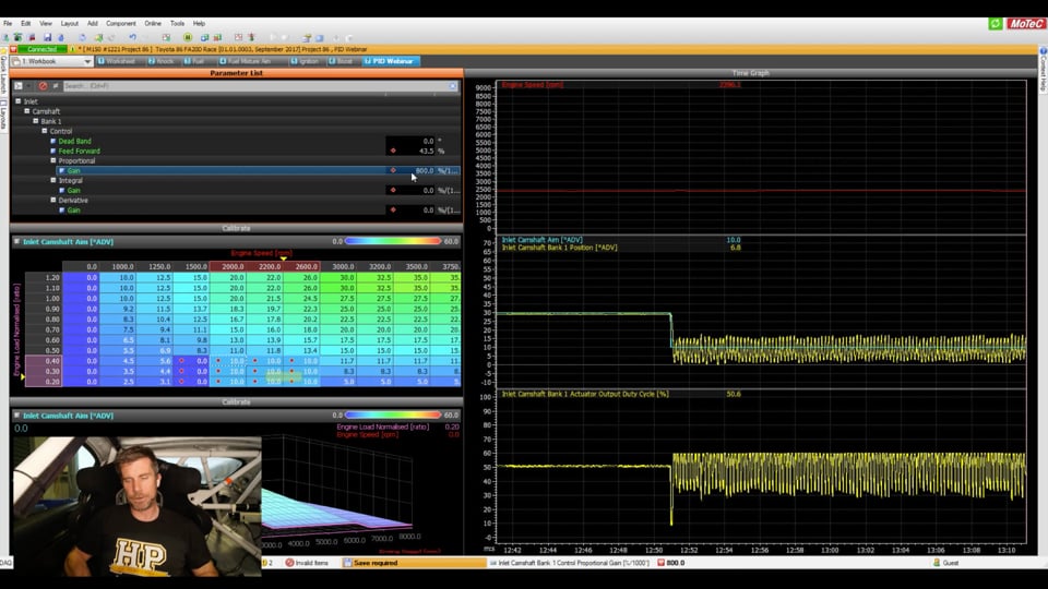
| 27:49 | Alright so let's have a look at this system at the moment. |
| 27:53 | So up here we've got our elements that we're interested in tuning. |
| 27:57 | In MoTeC lingo, which is technically correct but not a term that most ECUs use, the feed forward value, that is our base duty cycle value, so we can see that we've got that set to 43% at the moment, actually got some control in here at the moment so what we'll do is we'll set that to 0 and what we're going to do is start by zeroing out our P, our I and our D gains and we'll go through and set those up. |
| 28:24 | Alright so what we've got at the moment, our engine isn't running too happily here because obviously our inlet cam on one bank is now moved in a different position to the other one. |
| 28:36 | This is specific to cam control, I'll just mention here. |
| 28:38 | It's important with our cam control system, because it is a system that is controlled by oil pressure, it will be susceptible to changes in our oil pressure so we need to take into account that when we are doing this tuning, we want to make sure that our oil temperature is up to our normal temperature, we're not at the moment, it's coming into winter here, it's pretty cold so our oil temperature's about 40° colder than it should be right now and that will affect our response but normally I would make sure that my oil temperature's up in the maybe 80 to 100°C vicinity before I started this. |
| 29:11 | Likewise with our cam control tuning, the oil pressure is affected dramatically by our engine RPM and we're unlikely to get really good stable control at idle speed so for the purposes of this and cam control In general, I generally bring my idle speed up or my engine speed up I should say to maybe 2000, 2500 RPM so we'll just do that now and we've got our engine speed up here in red so we're just sitting just a touch below 2000. |
| 29:37 | Right so let's have a look at what we've got here. |
| 29:39 | Our blue, let's try circling that a little bit nicer, our blue is our target there, sitting at 20°. |
| 29:44 | Now doesn't really matter what I do with this at the moment, we'll set that to 0, absolutely no effect on our yellow parameter which is our current cam position. |
| 29:53 | Reason of course being that our cam position, we've got no PID gains so our cam position is not being functioned, it's not being actuated, we're in open loop control right now. |
| 30:04 | So remembering our first aspect here is to adjust our feed forward. |
| 30:08 | Now with a cam control system, remember again what we're looking for is the sort of value, the sort of duty cycle that is going to give us basically stable cam control, neither advancing nor retarding. |
| 30:22 | This would typically be somewhere around about 50% but it is not always 50% and also if you're dealing with an engine like our FA20 where we've got 2 intake cams, we're controlling them independently, you'll normally find that the feed forward value or the base duty cycle value for 1 cam on one bank is not the same as the other. |
| 30:42 | So let's go through this, we're starting at 0 here with our feed forward value and what I'm going to do is just simply step this up, I kind of know that we're going to be pretty close to 40% so let's just get ourselves a bit closer to this. |
| 30:55 | While I'm doing this, I'll just circle this, we want to watch this yellow value here. |
| 31:01 | You can see at the moment it's sitting at 38° so that's actually the maximum advance value that the cam can achieve. |
| 31:08 | So we're coming up to 38%, 40% and we're looking for the value where we first start seeing movement, now see that the cam is now retarding, as I'm talking we're dropping through 16, 15, 12, 10° so we've got 45% duty cycle, what we'll do is I'll just reduce that duty cycle. |
| 31:27 | So 43, you can see that I can actually control the cam just by adjusting this value. |
| 31:34 | 43.5%, at the moment it's holding pretty flat, we go to 44%, it's starting to retard back down to 0. |
| 31:40 | Now this can also show you essentially how the cam control system works. |
| 31:43 | Now if I drop this down quite aggressively from 44.5%, see the more aggressively I drop it, the more sharply that cam advances up but essentially what we're trying to do is find that point there where the cam is holding stable. |
| 32:00 | And it looks like within reason, about 44% duty cycle there so we're going to lock that number in. |
| 32:08 | So that's our feed forward value, now yes depending on our RPM, and depending on the specifics of our oil pressure and temperature, that will move around a little bit, we don't have to be perfect, the closed loop control is still going to come in and activate this but we just want to find that duty cycle where we are at least pretty close to holding steady so let's call that 43.5%, I'm starting to split hairs now. |
| 32:30 | Alright so that's our first control set up. |
| 32:34 | Now what we're going to do is go through and add our proportional gain. |
| 32:38 | Now I've already mentioned that the actual numbers that work for a given system are very dependent on the ECU and the type of control that we are dealing with here. |
| 32:47 | So I already know from my base map and got a lot of experience on this particular ECU, I'm going to probably end up with a proportional gain somewhere around about the 600 to 800% so if I'm starting with values of 1 or 2 and doubling those, that's going to take me a hell of a long time to get where we want to get to so let's just start though by going to a value that should show us some level of control, let's enter a value of 50 for our proportional gain. |
| 33:13 | Straight away we can see that our cam position is moving towards our target. |
| 33:17 | Not very quickly and it's probably not going to get all the way there but it's getting towards our target. |
| 33:22 | Now any time we are doing PID tuning, what we want to do remember is always ask for step change in our target. |
| 33:29 | We want to assess how well the system tracks that step change. |
| 33:32 | So you can see now while I've been talking, we've reduced down but that error's kind of stabilised out at around about 1.5-2°. |
| 33:39 | It's actually not too bad but particularly for a cam control system, I'd like that to be a little bit closer. |
| 33:44 | Anyway, what we're going to do again is we'll just highlight all of those cells and we want to ask for a reasonable sized step change so let's go with 30° and see how we respond. |
| 33:54 | Alright so it's responding but it's really really slow, that's definitely not going to cut it for cam control, you can see that it's taken probably a good part of a second to get close to our target and again we've got that remaining error so it's not doing what we need it to do. |
| 34:08 | Alright so first change there, simple, let's double it and we'll see how that works. |
| 34:14 | So again while I'm talking here we can see we've still got that error, it's moving around little bit, got about a 3° error so again not going to cut it for cam control. |
| 34:21 | What we'll do now is we'll target 10°. |
| 34:24 | Now with cam control, boost control, doesn't really matter, whatever we're targeting we also want to make sure that the values that we target, we can actually allow the system to overshoot on both sides, this is relevant for cam control particularly because if we've got a normal cam control system, we'd be limited to 0° retard on our intake cam. |
| 34:45 | So if we're going between say 20° and 0°, that's artificially going to limit the potential of the system to overshoot or in this case undershoot when we drop from 20° back down to 0 because 0 is the mechanical stop, it can't go any further than that. |
| 35:00 | So always want to choose values where we physically can see the system overshoot and undershoot. |
| 35:06 | Alright enough talking there, let's target 10° and we'll see how it responds. |
| 35:10 | Terrible, still absolute garbage, alright that's fine, we know that we're going to be up around probably 600 to 800 so we're nowhere near there so let's quickly double this, we'll go to 200, then we'll do our step change here so we'll come back to our target, let's go from 10 to 30°. |
| 35:27 | OK see how much quicker that was just with two iterations of changes. |
| 35:31 | It's still no good, we're still not on our target, we've still got that remaining error but see how much quicker it was to step up, let's go back down to 10° and we'll see that. |
| 35:39 | Again, faster than our previous change so we know we're going in the right direction. |
| 35:44 | Now because we're doubling the gains as well we should see the effect of this start to become a little bit more prominent so we'll go from 200 to 400, straight away while I do this, we'll just pause it, this is where I made that change and we can see that straight away the effect of that proportional gain allowed the system to remove a little bit of that error, as I said it hasn't got rid of all of it but we're a lot closer, we'll just get our time graph back up and running, alright let's do our step change again, go up to 30°. |
| 36:12 | OK really fast response there, no real overshoot, we've still got that error there, let's come back down to 10°. |
| 36:19 | OK, overshoot there but we've got basically that same situation where regardless we're always sitting below our target so we're probably getting pretty close here but I want to just show you the effect of too much proportional gain so we're going to go to the point where we actually lose control of this system so with our next change we'll go to 800. |
| 36:39 | Come back into our target map, let's go back up to 30°. |
| 36:43 | OK so we've got to the point now where we're getting that overshoot, you can see that we've got that initial overshoot where we first end up coming up here and we've reached a maximum value in this case of 37° so we want 7° past our target, then it's come back and it's stabiised. |
| 37:00 | Let's go back down to 10° and we'll probably see that same effect, yeah a little bit of an undershoot, now this probably in all honestly isn't a bad place to be. |
| 37:08 | Because we can probably fix most of that overshoot and undershoot up with some derivative gain but we see exactly how that all pans out but again I want to show you the extremes of this so let's double this again. |
| 37:19 | So obviously now as we double this we're making much more significant changes to our gain, come up to 1600, this should be just about enough for us to lose control, just bring my RPM back down so we're relatively stable. |
| 37:33 | OK so you start to see that oscillation there, I'll just pause that again. |
| 37:36 | See this little oscillation, now it's taken a couple of hits to get our target right, get onto our target, you can see this as well, I haven't actually talked about this bottom group of values here but this is our duty cycle, so that's what's actually being sent out to our wastegate solenoid, sorry our cam control solenoid and you can see the effect of that, it's basically been bouncing in our duty cycle. |
| 37:58 | Alright let's get our time graph up and running, we'll go one more change here just so we can really see hopefully that oscillation. |
| 38:06 | So straight away, and I go to 3200 and that's a really big number for our gain. |
| 38:10 | If we pause our time graph we can see, there's a sort of constant noise now on our cam control solenoid duty cycle and again that's just an indication that we're right on the limit there so let's see whether we lose control, we'll come back down to our target, we'll go from 10 down to, sorry down to 10 and you can see yep complete loss of control there, you can see that our cam position is just constantly oscillating there, going between about 20° and about 5° or 0° actually and our duty cycle's doing exactly the same. |
| 38:42 | So that's indicative that we've gone too far. |
| 38:44 | We actually know that a number of 800 looked like it was probably not a bad place to start so let's just jump back to there. |
| 38:51 | It's important to understand with our PID tuning as well, don't have to lock down a number right here and now, it's an iterative process, we can always come back and manipulate this later, but I know that a value of 800 was pretty good, we were getting reasonably good control. |
| 39:05 | So we have that overshoot and we want to get rid of some of that overshoot so let's see how we can do that. |
| 39:11 | Derivative gains in this system, I know that I'm probably going to settle somewhere in the region of about maybe 40-80% so let's start with a value of 10 here and we'll see how that works. |
| 39:23 | So again we're going to come back and make our step change. |
| 39:25 | Remembering that we were seeing that overshoot so let's see, with a value of 10 I'm expecting we're still going to have that overshoot, it'll be pretty prominent. |
| 39:31 | And exactly it is, so we haven't really seen much effect from that, we'll go back down to 10. |
| 39:36 | Actually on 10 it's actually pretty good. |
| 39:39 | So probably some effect from that but definitely not enough, let's go to a value of 20% there. |
| 39:45 | Come back to our table and we'll go back from our step position of 10 up to 30. |
| 39:51 | So you can see how that has reduced that overshoot it's actually looking pretty good now. |
| 39:55 | Remembering of course we're still settled a long way off our target but don't worry about that, we can fix that up. |
| 40:00 | So still a little bit of work to do there but let's bring ourselves back down to 10. |
| 40:04 | And yep no overshoot there but we didn't have that last time. |
| 40:08 | Also important to mention with our cam control, we did quite often see this effect where the response on an advance is not quite the same as the response on retard and this is because the way that the engine operates, it's easier to go one way than the other. |
| 40:23 | Let's double our derivative gain again we'll go up to 40, come back down to our cam target and we'll go up to 30. |
| 40:30 | So now you're starting to see, I'll just pause this for a second, starting to see that we've got this sort of rounding now. |
| 40:38 | So this is pretty much indicative that we're probably in the right sort of vicinity. |
| 40:43 | What I might do here is we'll just zoom this in a little bit as well because I'm hoping what we should be able to see, resolution here, the frequency we're logging doesn't really show this but this is our response here to our error. |
| 40:57 | So what we can see is as soon as we target 30°, our cam actuator duty cycle is increased to 60%. |
| 41:04 | So that drives us towards our target. |
| 41:06 | But the effect of our derivative gain, we can see that at this point here, we are still below our target, we're only at 11°, our target is 30° but already, the effect of that derivative gain, we can see has been to reduce our actuator duty cycle and in this case, probably a little bit too far. |
| 41:26 | It's just, again it looks a little bit better when we zoom out but we can see that we've sort of had this effect where it has kind of sort of rounded off that so that's what we're trying to basically get a nice compromise between a sharp response with our overshoot and not slowing down our response too far and this is where coming back in, iterative changes between our proportional and our derivative can be beneficial. |
| 41:52 | Let's see what happens when we go the other way though so well come back to our target map. |
| 41:56 | We'll enter a value of 10°. |
| 41:59 | And again we can see that rounding there so probably here a little bit less derivative gain or a little bit more proportional gain would be probably the key. |
| 42:12 | So just try here, we'll go back down to 30, I'm not going to repeat this test but that's probably going to be there or there abouts. |
| 42:19 | OK our integral gain is our last element and that's going to be used to remove that significant remaining error, right now while I'm talking we can see that our target's 10°, we're 5° off with an actual position of 5°. |
| 42:32 | Again numbers in the integral gain are probably around the 400 to 600 so I know roughly where I'm going to be. |
| 42:39 | Let's enter a value of 50 in here and we'll see what happens. |
| 42:43 | Not really a lot but as I'm talking here, we can see that we are driving towards our target, albeit very very slowly. |
| 42:50 | Probably not going to be fast enough, let's come back to our cam target and we'll go from 10 up to 30°. |
| 42:58 | Straight away you can see even with that relatively small amount of integral gain, how much closer we are to our target. |
| 43:05 | Come back down to 10, got that slight undershoot there, or overshoot depending how you want to talk about it, when we go from 30 down to 10. |
| 43:14 | Alright so let's double our integral gain, we'll go from 50 to 100, we should find slightly better response there, we'll go from 10° to 30. |
| 43:23 | Really really good response on the advance there from 10 to 30. |
| 43:27 | See what happens when we go back down to 10. |
| 43:30 | Pretty good, you can see how much less error we've got, we're sitting around about 0.5° off our target and it's pretty good so in all fairness this is probably better already than most cam control systems I see tuned on an aftermarket ECU. |
| 43:44 | Let's just see what happens when we double that integral gain again, we'll go from 10 up to 30. |
| 43:51 | Now we've got a slight overshoot here but again we're within 0.5° of our target so it's not too bad. |
| 43:57 | And back down to 10 and again we've got a slight overshoot so perhaps we've gone just a touch too far there with our integral gain, remembering again our integral gain does act a little bit like our proportional gain because it does work relative to the size of our error over time. |
| 44:13 | Right so I could go through another few iterations but hopefully at this point you're getting an understanding of what we're going through and it is just that iterative process but what I do want to do is just demonstrate the effect of our integral windup. |
| 44:25 | So you may remember that our maximum advance that we can realistically get here was 38.5°. |
| 44:32 | What I'm doing to do is just come up to 37°. |
| 44:36 | We should get pretty quick response right onto our target. |
| 44:39 | Yep we're pretty good there so we'll go from 37° back down to let's say in this case, 20°. |
| 44:46 | Really really good crisp response there and what I want you to sort of focus on here is this part here, the shape of that, how quickly it drops. |
| 44:54 | So what we're going to do now is we will just repeat that test but this time I'm going to target a value of 60°. |
| 45:03 | Alright we cannot get to 60°, I'll just bring my RPM up a little bit further. |
| 45:07 | So you can see that the system is tapped here at 38°, I'll do just to give you a little bit more power to that as well, we will go to 800% for our integral gain. |
| 45:22 | So now what I'm going to do is target a value that we can get to so we'll drop our target down to let's say 30°, let's say 25°. |
| 45:30 | See how much slower, how much more lethargic it is to track that change. |
| 45:36 | We'll just pause that there and we're done with that so we'll shut our engine off and you can see that really slow response there so we've got all of this error in here where we weren't able to actually track onto our target so that's the effect of integral windup and that's why it's so important to make sure that we are always targeting values that we can get to, regardless whether we're dealing with idle speed control, boost control, cam control or whatever else that may be. |
| 46:03 | Alright so hopefully that demonstration has been useful to really reinforce the topics of PID control and give you an approach to tune it, remembering the process there, make sure our mechanical system is capable of giving good control with no closed loop control active. |
| 46:21 | The next step with our closed loop control inactive, set up our base duty cycle table, our base position table, feed forward, whatever your ECU manufacturer calls it. |
| 46:30 | Start with our proportional gain, little bit of proportional gain, doubling that each time until we find the range of values that will give good control. |
| 46:38 | Once we're getting to a point where we're just starting to get a slight amount of overshoot then we can start adding derivative gain and then finally once we've got really good control with our proportional and derivative, we can add a little bit of integral gain just to clean up the pieces and get us to the finish line, getting right onto our target. |
| 46:56 | For now we'll have a look at our questions and if you do have any more please get them through. |
| 47:05 | Matthew's got our first question, do you have a cheat sheet for the PID steps you'd take from an unknown system? Matthew I have just given them to you, exactly, literally just finished giving them to you. |
| 47:17 | Proportional first, making small changes, starting with a small amount of proportional gain, doubling it until we find the limit of the control, you get to a point of slight overshoot, add derivative gain, again starting with a small amount, doubling it each time until we find the range of values that work with your system and then finally integral gain. |
| 47:35 | The key there is starting with a small value and doubling it and that's going to really quickly guide you in the range of values that that ECU system wants to see. |
| 47:44 | Remember, there's no real danger here, we get to a point where we have lost control of the system and it starts wildly oscillating, halve the value and that's going to get you back into the ballpark. |
| 47:57 | Suhas has asked, PID tuning is pretty much applicable most control systems. |
| 48:02 | What's the difference in PID setup in an open loop control system and closed control system? In closed loop control we get feedback so we know how we can chase our target. |
| 48:12 | How do we do that in open loop? Ah well the definition of open loop is we're not chasing our target, it is just outputting a fixed value and irrespective of the measured value, there is no PID control effective during open loop, it is simply blindly outputting a value and irrespective of what we end up with on the system we're controlling, the ECU's going to do nothing about it. |
| 48:34 | Now I will just mention here, particularly with boost control where I've run into a number of ECUs which really struggle irrespective of how good the tuner is to get good closed loop control. |
| 48:46 | The link G4+ is one that we demonstrated to the manufacturer that there was an inherent problem with their own closed loop control strategy. |
| 48:55 | So I actually refused to tune closed loop control on the G4+ ECU, the G4 is the same. |
| 49:00 | Because I'd get really really rock solid stable boost control on the dyno, take the car out on the road and we'd get overshoots, oscillations and basically chase my tail for an hour and end up getting poor results so I basically instigated what I call passive closed loop control which is not using PID, in that system what I did was had a wastegate duty cycle table and RPM would be one axis, I'd use manifold pressure as the load axis for the table. |
| 49:30 | And what this allowed me to do, let's say we were targeting 200 kPa, we're getting all that dialled in on the dyno and then as the boost pressure goes above 200 kPa, I'd actually pull duty cycle out of the table. |
| 49:42 | So this passively just reduces the duty cycle which has the effect of dropping our boost pressure. |
| 49:47 | Likewise if the boost was a little bit below my 200 kPa target, we would increase the duty cycle. |
| 49:52 | Now this needs to be done carefully, we're only talking relatively small changes. |
| 49:57 | 5 kPa plus and minus, I might be making changes of 0.5% to 1% duty cycle so if you are too aggressive with that system it will result in oscillation as well. |
| 50:07 | Just Goofin's asked, after all the gain adjustments, would it be possible to adjust the duty cycle to further fine tune? It can be, so this again depends on the sytem. |
| 50:18 | So if we're talking about boost control, we'll generally find that there's limitations on the solenoid we are using. |
| 50:25 | The MAC 3 port solenoid that is probably still far and away the number 1 most used solenoid, generally you're only going to find that that will work of function really well between about 20 and maybe 30, 35 Hz. |
| 50:40 | Much higher than that and the solenoid just simply won't function. |
| 50:43 | You'll find that at lower frequencies you're actually going to end up introducing oscillation just because of how slow the system works. |
| 50:51 | That would also be completely true of cam control. |
| 50:55 | Obviously with a system that moves very quickly we need to have a frequency for our control solenoid that's going to be suited to that system. |
| 51:04 | I'm never going to get good cam control if I'm pulsing the solenoid at 20 or even 50 Hz, it needs to be operating very fast, 200 to 300 Hz and I mean, we can get a guide on this by looking at how factory ECUs operate. |
| 51:17 | They obviously have their systems pretty well dialled in so we can learn from that but yes absolutely the solenoid duty cycle needs to be, or the output duty cycle needs to be suitable for the system. |
| 51:30 | If we're talking about idle speed control, particularly with a solenoid, you're probably going to want the duty cycle a little bit slower just because the idle speed system is so much slower to respond compared to the likes of cam control. |
| 51:44 | Suhas has asked, is it fair to generalise proportional part as the parameter to be controlled, integral as the amount of time integral of error required which increases the parameter to reach the target and derivative as the amount of reduction required of the parameter to reduce to come close to the target? I mean I think, I don't know I'm biased here, I probably like my description better. |
| 52:09 | I mean really it comes down to understanding what those terms mean. |
| 52:12 | Proportional, really the hint is in the name, the effect is proportional to the size of the error so if we understand that, the larger the error, the more the effect that proportional gain will have, in other words the faster it will drive us towards our target. |
| 52:26 | The derivative, this is relative to the rate of change of error so it's going to have more effect when our error rate is changing quickest. |
| 52:34 | Basically when our, we're moving towards our target fastest, the derivatives going to have more braking effect and the integral, as it's name implies, is relative to time so that's going to remove our error over time. |
| 52:46 | Next question, that was one of the best examples I’ve heard of PID control with the acceleration, I guess that's actually more of a comment than a question but Instr05734, I'll take it, I'm glad that you liked it. |
| 53:01 | We've got one more from John who's asked, is there anything special to consider for an electronic throttle body setup? Yes, liability is what you need to consider there. |
| 53:14 | This is tricky because drive by wire throttle body obviously has a significant affect on the potential safety for our vehicle. |
| 53:23 | For this reason, you are going to find that most aftermarket ECU manufacturers are very very fussy with how they deal with this. |
| 53:31 | MoTeC for example because I'm using that system today, they will provide characterisation, that is just simply a term that means it gives you all of the data required, the proportional, integral and derivative gains, the frequencies etc, for a specific throttle body based on that part number and that is what you must use or at least it's highly recommended. |
| 53:54 | If you're dealing with a throttle body that hasn't been characterised by MoTeC, you can often at some expense, send that throttle body to MoTeC via one of their dealers and MoTeC will actually do the characterisation for you. |
| 54:08 | So it's highly recommended that you use developed characterisation data unless you are very very comfortable with PID tuning because understandably we looked at cam control there and I set the system to oscilate, lose control, that's not a big deal for cam control, the engine's going to run a little bit funny but it's not going to hurt anything. |
| 54:30 | If you had the same effect with drive by wire throttle, you're going to have a potential for a crash. |
| 54:36 | Drive by wire throttle systems also have the benefit of some safety sub systems in there so typically if you are getting significant errors compared to our target, the system will normally shut off the drive by wire output and maybe also instigate a RPM limit but yeah just really needs to be treated with care John because there is so much liability if you get that wrong. |
| 55:00 | Wedge has asked, are there any types of devices that could get damaged by using completely wrong PID values? Eg. solenoids, drive by wire motor, fuel pump. |
| 55:09 | So solenoids, if we output the wrong frequency to them, it's not really a duty cycle thing, if we output the wrong frequency to them, we're going to get to a situation where the solenoid simply can't function so it just doesn't work. |
| 55:28 | Drive by wire motor, I can't say for sure, I've never personally seen it but if you were to use very incorrect PID control gains and you set the system into oscillation, you didn't catch it quickly, yeah I'd say there's possibly the potential to damage it, very unlikely. |
| 55:45 | I'd say in 20 years of tuning professionally for a living, I haven't seen anything damaged from incorrect PID so it's pretty safe to experiment with this and find the values that work for your particular system. |
| 56:00 | I mean even today, you watch me set that into oscillation, I left it there for a fairly long period of time while I was talking about it, I had absolutely no concerns about doing any damage but normally when we're actually tuning we're going to be able to pick this up really quickly, we're not explaining to someone else on the other end of a camera what we're doing so we start to set up an oscillation, we'll back off the throttle or change the value back to what it was so yeah, there's not really a lot of reason for us to be in a situation of poor control like that for extended periods. |
| 56:30 | Alright that's all the questions we have got for today and for our members, remember if you've got any questions on this after it's aired, please ask those in the forum and I'll be happy to answer them there, thanks for joining us, hopefully we can see you next time. |
Timestamps
0:00 - Intro
0:35 - Open loop vs closed loop control
2:55 - Demo
5:45 - PID applications
6:25- How does it work?
7:50 - Cam tuning example
9:25 - Idle speed control example
11:05 - Closed loop control is not a bandaid fix
13:50 - What does P, I and D mean?
17:25 - Practical analogy
19:40 - Integral windup issue
21:45 - Tuning process
27:30 - Tuning demo
44:20 - Integral windup demo
46:05 - Tuning process summary
47:05 - Questions


