288 | How to Use Autosport Connectors
Summary
Autosport connectors are the gold standard in professional motorsport wiring, but working with them correctly requires the right knowledge, the right tools, and the right technique. Get any of it wrong and you compromise the reliability of the entire harness.
In this webinar, you will learn everything you need to know to correctly specify, terminate, and install Autosport connectors in a motorsport wiring harness. The principles covered apply whether you are building a full milspec harness or adding a single bulkhead connector to an existing build.
Topics covered:
- What Autosport connectors are and why they are used in professional motorsport
- Souriau vs Deutsch and how to decode the connector part numbers
- Choosing the correct shell size, contact layout, and keyway orientation
- Current handling, wire gauge selection, and when to double up positions
- DMC crimp tool setup, positioner selection, and crimp tension settings
- Correct strip length and how to achieve a reliable crimp
- Pinning and depinning procedure step by step
- Handling shielded cables with solder sleeves
- Service loops, booting, and sealing unused positions
Most importantly, you will learn the correct process from connector selection through to final installation, so your terminations are reliable enough for professional motorsport use.
| 00:00 | - Hey team, Andre from High Performance Academy here, welcome along to another one of our lessons. |
| 00:04 | And in this lesson we're going to dive into the world of autosport connectors, we'll find out a little bit more about what they are, we'll find out why they are used in milspec or professional motorsport wiring harnesses, why they've become essentially the go to, despite the relatively hefty price tag that comes along with them. |
| 00:24 | We'll look at what you need to understand when it comes to actually specifying a suitable autosport connector for your particular application and then we'll also have a look at a demonstration in real time where we go through the process of pinning and then depinning the connector. |
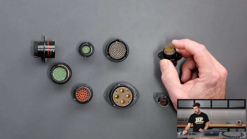
| 00:39 | Now for a start, let's just head over to our overhead camera and I've got a little selection of autosport connectors here. |
| 00:46 | As you can see straight away, they come in a range of different sizes and styles. |
| 00:51 | We've got one that is connected up here. |
| 00:54 | This one in particular has a two bolt flange on it which we'll learn a little bit more about. |
| 00:58 | We've also got the option to have them as an inline with no flange at all. |
| 01:04 | We've got this one here, obviously as you can see, even from our overhead camera, much larger contact sizes through that particular connector, used more for getting main power feeds through a bulkhead or something of that nature. |
| 01:17 | Actually the other one that I do want to show here, this is probably more in line with what we'd see from an ECU manufacturer, this one does have a two bolt flange but you can see that it is also designed for mounting direct to a PC board so when you see the more high end autosport equipped ECUs on the market, that's the sort of connectors that we find attached to those. |
| 01:40 | The key point here as well is in terms of who is in this market, we essentially have two manufacturers, we have Souriau, excuse me if I'm pronouncing that incorrectly, French brand, and we also have Deutsch with their autosport range. |
| 01:56 | Essentially these are interchangeable though, they are made to exactly the same military specification and essentially we can interchange them between the two brands. |
| 02:07 | Basically often what it does come down to is where you are sourcing your particular connectors from, what actually the supplier has on the shelf at the time but basically there's no advantage or disadvantage between either of those two brands, both are super high quality, both completely suitable for the types of tasks we're going to be using them for in a motorsport harness. |
| 02:31 | The question next comes why do we want to use an autosport connector and the reality first of all is that this is absolutely not a must have for every harness. |
| 02:42 | And in some instances it would be hard to justify the additional expense going to an autosport connector. |
| 02:48 | These can cost several hundred USD for a mating pair of connectors depending on the specific model and contact size that you're going for so obviously if you're looking at a lightly modified street car, maybe you've performed an engine swap, absolutely it's not essential. |
| 03:06 | Where we do see them being used much more regularly though is in professional motorsport where the cost of the car, the cost of competing becomes significantly more than the cost of what actually goes into the harness so there reliability is the key and these are definitely a more reliable connector. |
| 03:25 | One of the parts that's actually really easy to overlook is that if we're considering a factory connector on our car, let's say we've got our showroom stock engine, stock car with the factory harness in it, obviously there's going to be connectors at all of the sensors and the actuators on the engine so if we want to remove the harness from the engine we understandably need to remove the connector from each of those actuators or sensors. |
| 03:52 | Likewise if we need to replace a sensor or an actuator, same goes. |
| 03:55 | Now the problem that again is easy to overlook is that these factory connectors are really not actually designed for multiple insertions and removals. |
| 04:04 | Obviously it's going to totally depend on the specific connector but some of the numbers that I've seen are only in the order of 20 insertions and removals. |
| 04:12 | Now for a factory road car, that's absolutely no problem, it would be very unlikely for it to see that many removals and insertions in its lifetime but in the motorsport world, this is something that we do regularly see. |
| 04:25 | So in terms of the specification for the autosport connectors, these are rated at in excess of 500 insertions and removals so obviously that should easily last the lifespan of the racecar. |
| 04:39 | In terms of that as well, they are really really quick and easy to insert and remove. |
| 04:45 | So I'll try doing this under our overhead camera. |
| 04:49 | So what we can see is that we have these little solid tags sticking out here or pins sticking out of the connector body. |
| 04:57 | If I turn this over as well, we can see that we do have, might be a little bit hard to see, little keys around the outside, we'll talk more about these and the relation to the coloured band shortly, and the idea here is that all we need to do is gently turn that until those keys lock into place and then just a simple quarter turn, we hear a nice satisfying click, we can see those little pins through the inspection hole there, we know that it is inserted properly and our autosport connector is completely connected. |
| 05:25 | So it's quick and easy, we've got a guaranteed result there, it's all but impossible to end up with pins misaligned due to the design of the connector as well so great for reliability there. |
| 05:39 | So how this is used in a professional motorsport world of course is if there's an engine problem, the entire harness comes out with the engine and all the technicians have to do is that quarter twist at the firewall, throw the harness and the engine in the transporter, in the bin, I don't know, and they'll wheel out a brand new or replacement engine with a harness already attached, connect that up and they're good to go again. |
| 06:01 | So a great way of saving time, obviously at a significant expense but these again aren't for the light of wallet in most instances. |
| 06:09 | The other aspect there as well is that in a professional motorsport harness, you'll find that instead of using factory connectors, things like the injectors and the sensors will be potted and then terminated in a autosport connector as well, meaning that if one of those fails, it can also be replaced relatively quickly and easily. |
| 06:27 | The other aspect is environmental protection, these are rated at IP67 which off the top of my head I think, if my memory serves me correctly, rated at a submersion of up to 1 metre for 30 minutes so basically probably not something that I'd recommend for mounting to the outside of your submarine but for most of our motorsport applications, that is going to be absolutely fine. |
| 06:53 | The other aspect here as well is that we generally add further protection to these connectors using the likes of moulded boots. |
| 07:01 | So I'll just get this under our overhead camera here. |
| 07:03 | This is a harness that Zac actually built up for our RX7 as part of our professional motorsport harness course so we've got the autosport connectors, these are two bulkhead connectors that go to the firewall and we can see that they have in this case Hellermann moulded boots on the back of them. |
| 07:20 | These are also sealed with epoxy so basically just gives us another layer of environmental protection there that's going to end up improving the performance of these harness over the lifespan of the vehicle. |
| 07:33 | The other aspect, more important to professional teams than us at the amateur level but obviously they also save weight, they are lighter than a lot of the alternative connectors and they're also a very small footprint so they end up with a smaller harness. |
| 07:50 | That also makes it easier to basically mount in what can be quite a busy engine bay, you've got less physical real estate required to get that harness or autosport connector through. |
| 08:00 | Now the problem when it comes to choosing an autosport connector, I know for a lot of those just getting into building wiring harnesses it can be a bit daunting, if you look through a catalogue, knowing what to choose. |
| 08:14 | Now we'll just jump across to my laptop screen for a moment. |
| 08:17 | This is the Souriau catalogue and if we just scroll through here, it is quite daunting how many different configurations are available. |
| 08:28 | And basically decoding what all of the numbers in the catalogue mean can be pretty confusing. |
| 08:34 | And obviously we want to make sure, particularly when we're spending quite a significant amount of money, we want to make sure that what we are purchasing is what we think we're getting and what is going to be suitable for our particular application. |
| 08:48 | So what we'll do is we'll start by actually going through to page 17. |
| 08:53 | I'm going to decode the connector, show you how the numbers, at least for the Souriau range work. |
| 09:00 | So first of all, the series here is 8STA, so that's the actual series of connectors. |
| 09:07 | And there will be numbering printed on the actual connector itself so let's just have a quick look over here, we'll go to our macro camera. |
| 09:16 | And I'll just try and get this into a position where we can read it, sorry while I try and align this. |
| 09:22 | So it is a little hard to read, I will admit with the light but we can see as I rotate this, 8STA and then 01626SN so this is the sort of stuff that can on face value seem a little bit confusing, what the hell do all of those numbers mean? So let's have a look back on my laptop screen here and we'll see exactly what that means. |
| 09:49 | So first of all we had 8STA so that again, just the series number, no problem. |
| 09:53 | The next number here, in this case 0, we can see that this is the shell type, so this is whether we are dealing here with an inline connector, whether we're dealing with a receptacle or a plug, whether we are dealing with a flanged connector. |
| 10:11 | So you can see those numbers there, if I just circle them, basically pretty easy to decode. |
| 10:17 | So in our case, that one there was a 0 so we can see the top option there, oval flange receptacle which of course also matches what we can see on this. |
| 10:28 | So basically what we would use for a bulkhead connector. |
| 10:31 | The next option here is the plating so typically this will be blank and you can see there none is the standard version, it's possible to choose these in a nickel version or a composite version as well. |
| 10:44 | Then we have the shell size and this and the next number here are generally how we will refer to a autosport connector. |
| 10:52 | So shell size followed by our contact layout. |
| 10:56 | So in our case, let me just go back to our numbers here, this was a 1626. |
| 11:02 | So what this means is the shell size is 16 and the contact layout or contact arrangement is 26 so that tells us most of what we need to know, I'll go and show you how to decode that in a second. |
| 11:15 | But we've got the last two parts there which is in this case, ours was an S and an N, we can see that we've got a P and an N showing here but basically the first of those, P is for pin, S is for socket. |
| 11:29 | So this is really important because we can choose to specify a plug or a receptacle, either with a male pin or a female socket so these are the contacts the go inside these and if we go get this wrong we're going to end up with something that's basically not going to mate together so we need to have a plug and a receptacle, we also need to have a male pin and a female socket for our contacts so that everything is going to go together properly. |
| 11:57 | Really easy when you understand how that works but it is possible to get this wrong so making sure that we understand that. |
| 12:04 | So in our case again, this is a S so we know that this is a female socket that's going to go into here and by looking at this I also know that that's what that's going to be. |
| 12:13 | Last part here is N and this is the orientation. |
| 12:19 | So we could see, let's just go to our macro camera again as well. |
| 12:23 | We can see that there is a red band on this particular body and that is the colour of band we will see with that N value and what that basically defines is the keyway orientation for that connector. |
| 12:41 | We can see the, basically the locations where the keys are in that. |
| 12:45 | And this allows us to basically specify a connector, particularly if we've got multiple connectors in the engine bay, to ensure that we can't end up accidentally connecting two together. |
| 12:58 | We've got a good example of this in this harness which I will just show you under our overhead camera. |
| 13:04 | So these two connectors here, for all intents and purposes are exactly the same, they're the same shell size, the same contact arrangement but you can see this one here is a red band which is the S, same as the one that we're just looking at. |
| 13:18 | This one here, if I can just turn this around, this is a S and that's the yellow band there so basically different arrangement there for our keyway so it's just going to make sure that it's completely impossible to accidentally connect two connectors which are in the same location of the engine bay, into the wrong harness. |
| 13:41 | Alright so that's essentially what we need to understand from the code that it etched onto our autosport connector and again from the manual there it's really easy to just actually understand what that means. |
| 13:54 | I will also make a note here because I know we're probably going to get asked, I'll get Luke to drop a link to this particular manual and the TE Connectivity one from Deutsch in the comments that you can follow and basically have a look at this yourself. |
| 14:09 | Alright so we know what everything means there but what we also need to do is have a look at the more important part which was the shell size and the contact layout. |
| 14:21 | So let me just find the page where we've got that. |
| 14:25 | Which is this one here. |
| 14:30 | So ours was a shell size 16, which is this one here and the contact arrangement was 26. |
| 14:39 | Now this doesn't necessarily mean we've got 26 contacts through that particular connector either, that's important to mention. |
| 14:46 | If we look at this here, what it says is that a 26 contact layout or arrangement gives us 26 number 20 or size 20 contacts so that's what we've got for that particular arrangement, we've got 26, 20 gauge contacts that are going to be going through that. |
| 15:07 | So this is important information because obviously one of the first things we need to understand is how many particular positions through an autosport connector do we actually need for our application? Alright so now we've got a little bit more of an understanding about what everything means and hopefully the numbers on the connector body are a little bit less scary, we'll just go through some of those requirements, some of the things that you need to think about before it does come to actually specifying a connector for your application. |
| 15:38 | First thing as I just mentioned, we need to understand how many conductors we need to go through that connector. |
| 15:44 | There's no point ending up coming up short and having to put in a second connector or swap out to a larger one. |
| 15:50 | This sort of goes hand in hand as well with the sort of wire gauge we need which really comes back to how much current we need to support through this. |
| 16:00 | So most of our work, when it comes to ECU wiring for our engine, we can get away with probably either 20 or 22 gauge wire but that does limit the current handling and we may get some situations where we need more current than we can pass through a number 22 or a 22 gauge contact. |
| 16:21 | So just to understand how that all works, if we just head over to the TE Connectivity manual for a second, again you'll get a link to that that you can download. |
| 16:31 | So there's a bit of information here which we're going to use in a moment for another task but basically here in this chart we've got our contact size and then we've got this line here which shows our maximum current so if we come down to a size 22 contact, we can see that TE recommend this for a maximum current of 5 amps. |
| 16:52 | So what do you do here if you need to maybe get 10 amps or 7 amps through that? Well what we could do if we want 7 amps we can see that we could step that up to a size 20 contact, that will support 7.5 amps. |
| 17:06 | However it's going to end up making things bulky and personally given that a lot of our wiring for our engines doesn't require anything near 7.5 amps probably doesn't require anything near 5 amps even, generally what I like to do is work with 22 gauge wire for my harnesses. |
| 17:24 | And this gives us this problem, what say we do get to a situation where we need to pass 7 or 8 amps through it? What we simply need to do there is double up on the positions through a particular connector body so let's say for example we are wiring up a drive by wire motor and a drive by wire motor may pull 10 amps peak, may actually pull a little bit more than that but 10 amps would generally be pretty safe. |
| 17:50 | So what we can do there is still wire using 22 gauge wire but simply we run two positions for the half bridge positive and minus through the autosport connector. |
| 18:00 | This also does require a little bit of care because when we are doing this, we need to really plan this out thoroughly before we specify a connector because we may find that aspects like our drive by wire throttle, maybe some of our ignition coil requirements may need us to step up to two conductors per power feed instead of one so can be a little bit deceptive if we know we're just within the limits of how many positions we have through the autosport connector but then we overlook the fact that we're going to need to double up on maybe 6 or 8 of those conductors, then we can find that we're over the limit so just again a little bit of pre planning, a little bit of forethought and we should be pretty well good to go there. |
| 18:41 | There are also some particular connectors which do come with different gauge contacts through the same connector body. |
| 18:50 | So actually I think I should be able to find us one here. |
| 18:54 | This one here is a good example, a 16, a shell size 16 with a contact layout 99 gives us two 16 gauge contacts and 21, 20 gauge contacts. |
| 19:07 | So that can be useful for some applications where we have a couple or a few larger current drawing aspects or current drawing applications that we need to wire up. |
| 19:18 | But basicallly it's just a case of having a look through the catalogue, seeing what is available and seeing what suits your requirements. |
| 19:26 | Again depending where you are in the world, often you are also going to be limited by what your suppliers actually have on the shelf. |
| 19:33 | What we will find is that there are a handful of really common shell sizes and contact arrangements that suit a wide range of applications and rather than our supplier having 100s of different applications sitting on the shelf, many which people don't use, they will restrict themselves to a select few because again these are relatively expensive so having inventory sitting there doing nothing is not particularly useful. |
| 20:00 | Now the other aspect that always comes up when we talk about these autosport connectors is how do we deal with a shielded cable? So I've got a little example here of a shielded cable. |
| 20:11 | This is actually our concentric twist example. |
| 20:14 | We'll have a look under the overhead camera here and this is the core of our little concentric twist layup here and we've got basically two sections of two core shielded cable which would be typically what we use for some of the mission critical sensors on the engine such as maybe engine speed and position. |
| 20:32 | The idea with that shield of course is that it protects the conductors from RF interference. |
| 20:37 | Electromagnetic interference and basically ensures the integrity of the signal in those conductors which is great because that's what we need for those sensors such as engine speed and position, we want to be really sure that we're not going to get interference on those, affecting the ECU's calculations or measurement for engine speed and position. |
| 20:56 | So this gives us a problem, we obviously need to break the braid there and re instigate it on the other side of our connector if we're talking about a bulkhead connector and the way we go about doing this is to use what's called a solder sleeve. |
| 21:12 | And this is probably one of the few areas where I wholeheartedly accept using solder in a motorsport application so this is a typical solder sleeve, this one's a little bit large for the application but these can come pre terminated which is what we've got here with a shield wire already attached. |
| 21:30 | Or you can get them just as the sleeve themselves. |
| 21:33 | Now I've seen some dodgy videos on YouTube recently showing these for joining wires together but this is a proper Raychem product as well and it's designed for the purpose. |
| 21:42 | So what this is is a heat recoverable sleeve. |
| 21:46 | It is semi rigid when it's recovered which is important because that provides strain relief. |
| 21:50 | The red band that you can see in the middle there is a band of solder and then at each end we also have some adhesive in there. |
| 21:58 | So the idea is what we do is we strip back the insulation around our braid, we'll cut our braid and terminate our conductors inside to pins or sockets to go through our autosport connector and then we'll leave a section of exposed braid, basically this gets slipped over the top there, so that the red band is contacting over the top of our exposed braid. |
| 22:19 | The rest is pretty straightforward, we shrink that down using our heat gun and the idea behind it, why we can get away with this is twofold, first of all when it is recovered, as I've mentioned, it's semi rigid so that removes the potential for flex and movement in the finished soldered joint. |
| 22:35 | The other aspect though is it's got a very controlled amount of solder in there so it's not going to end up wicking up the braid an extensive distance and causing problems outside of the actual solder sleeve so it is a very reliable way of terminating our shielded braid. |
| 22:51 | So once we've got that, we then end up in a situation where we have our two conductors, in this case a two core shield, this would be for a reluctor sensor for example where we'll have our signal in ground. |
| 23:01 | So those will go through two locations in our autosport connector. |
| 23:05 | We'll then run our shield drain there that we've just added in with our solder sleeve through a third location and then we'll basically do the reverse of that process on the other side. |
| 23:13 | So this works out to be really effective. |
| 23:16 | We will obviously have a very small section where that shield is interrupted but at least in my experience and in the experience of motorsport in general, this does prove to be reliable and it isn't a problem. |
| 23:28 | Right so also worth just talking about what we actually get in the box when we purchase an autosport connector. |
| 23:36 | So we'll grab one here, this one is actually a Deutsch connector and they do generally come in a nice little vacuum packed plastic bag like this so we'll just crack that open. |
| 23:47 | First of all we'll just talk about what this is. |
| 23:50 | Let's get it under our overhead. |
| 23:52 | The strategy for naming an autosport connector, Deutsch autosport connector, slightly different to the Souriau but essentially once you understand them, much the same. |
| 24:02 | We've got AS, autosport, the first number here 1, this just dictates whether this is inline or a plug receptacle, bulkhead connector etc, we've got the contact, the shell size and the contact arrangement and then we've got the same, we've already looked at our keyway and we've got our orientation. |
| 24:23 | Right so once we've got an idea of the fact that we've actually purchased the correct part, obviously that's pretty essential, we can actually open that up and we'll see what we've got in here. |
| 24:37 | And we've got our connector itself, we've got our contacts and then we've got our little insertion and removal tool. |
| 24:46 | And just to clarify there, the last letter there is our orientation so that is our keyway and our colour. |
| 24:56 | So in this case we'll see that that is of course yellow, not the red that we were looking at previously and then the other part is whether we've got a pin or a socket so just to calrify that. |
| 25:06 | So in this case this is pins, male pins which is what we can see here. |
| 25:10 | So that's the parts that we're going to get in our packet and this is essentially everything you're going to need to terminate that particular connector. |
| 25:17 | Now what we're going to do is go through a bit of a demonstration here of how to actually crimp one of these, how to terminate everything and we'll just get this out of the way. |
| 25:27 | Also just worth mentioning here the insertion and removal tool, these do come in different colours relating to the size of the contacts for our particular autosport connector. |
| 25:38 | This one here, the orange and red dictates that this is for a 20 gauge contact. |
| 25:44 | The green and white there is for our 22 gauge contacts. |
| 25:53 | So one of the parts that does put people off working with autosport connectors, above and beyond just the cost of the connector itself is the tooling that is required to work with them. |
| 26:05 | Unfortunately it's not possible or at least I certainly wouldn't recommend working with cheap generic tooling. |
| 26:12 | If you're going to spend the money on autosport connectors, you really want to be assured that you are going to get the best possible result and reliability from the finished termination so it is really invaluable to be working with the right crimp too, the industry standard is the Daniels Manufacturing Corp or DMC crimp tool, this is an AFM8. |
| 26:33 | We'll get this under our overhead and have a quick look at what we've got here. |
| 26:38 | So probably seen something like this before, it's pretty straightforward there, it's a ratchet style crimp tool, nice thing about the ratchet style crimp tool is it does ensure that you always achieve the same amount of crimp because basically once you've started the crimp you can't actually release the contact from the end from the crimp until you've gone the whole way. |
| 27:01 | So that's really important, we've also got a little adjustment here which we'll have a look at in a bit more detail, so we can actually adjust the depth of the crimp to suit what we are crimping. |
| 27:12 | At the end here we have a location for a positioner, we'll get a positioner under here. |
| 27:16 | This is another area where I know a lot of people get confused so we'll talk about what these are and how to choose the correct one. |
| 27:23 | Essentially there's no magic here, the positioner is just designed to support the pin or the socket and make sure that when it is inserted from the other side that it is located correctly so that the little jaws, which hopefully we can see in there, locate in the correct position on the contact that we are crimping. |
| 27:43 | Fairly complex little tool there that's designed to achieve a very reliable and consistent repeatable crimp result. |
| 27:52 | The downside is, you will be paying for them. |
| 27:54 | Depending exactly where you're purchasing them from, you're probably expecting to pay somewhere in the region of about $350 USD. |
| 28:01 | The positioner and depending on what contacts you are working with, you will need a number of these. |
| 28:06 | These are also somewhere in the range of about $50 -$60 USD as well so it does start to add up. |
| 28:12 | You're going to be probably north of $400 USD, probably $450 for a couple of positioners to get yourself started. |
| 28:18 | Good news is that it is a really high quality tool, if you look after that well, it is going to last you a lifetime. |
| 28:26 | I will just also warn that I have seen some Chinese rip offs of the DMC crimp tool, unsurprisingly coming up, I would highly recommend you stay clear of those. |
| 28:38 | I cannot talk about the quality or reliability that you're likely to get from these and again, if you are investing in the expensive autosport connectors, it only stands to reason that you want to get the best possible results from the finished crimp. |
| 28:54 | OK so important to understand though as I mentioned how to select the positioner that is going to be suitable for your particular application. |
| 29:05 | And again as long as we understand where to find this information, it really isn't particularly difficult. |
| 29:10 | If you're doing this all the time you're going to just end up knowing off the top of your head for a particular contact, whether it's a pin or a socket, what size it is, what you are going to be using but if we come back over to my laptop again, this again is the TE Connectivity technical manual that we've linked to so you can have a look at that. |
| 29:28 | But in this reference guide here, we've got the contact size. |
| 29:31 | So that's over on the left hand side, so for example what we're going to be looking here at terminating, uses a size 22 contact. |
| 29:40 | So that's where we are there. |
| 29:41 | You can also just inspect the genuine contacts and they will have these little coloured bands at the end. |
| 29:49 | Let's see if I can grab one and just show you. |
| 29:54 | Might be a little bit tricky but I'll try this under the macro camera. |
| 29:57 | Just so you can see. |
| 29:59 | Yeah it's a little difficult but we've got an orange a green and a grey band on that so yeah actually should be pretty clear to you. |
| 30:06 | So that just allows you to just know that, I said green but I meant grey, that should allow you to just confirm what you actually have got here and you can actually see that that aligns, unsurprisingly here, orange, yellow grey. |
| 30:22 | Pretty sure I said green, I meant grey. |
| 30:24 | Anyway that's what we've got. |
| 30:25 | So coming along here we can see that we've got this section here for the correct positioner so we know that for you particular application there, for our particular contact, we want to be using this particular positioner. |
| 30:38 | Which is the one that I have already selected so we do have a range of these but just make sure that that is correct, which is the M22520-207, you can see that on the top of the little box. |
| 30:53 | These do come in a nice little protective box as well so you end up with quite a few of these and you can store them and keep them in a suitable place that's going to keep them out of harm's way and they're going to be there when you need them so we'll insert that one back into our positioner. |
| 31:11 | Now the other part we do need to understand when we are working with these contacts is we need to adjust the crimp tension for our crimper. |
| 31:20 | So I've already talked here just briefly about the ability to rotate this little dial here to suit. |
| 31:26 | It might be a little difficult to actually see on this, let's try getting this under our macro camera for a second and we'll see if we can make this a little bit clearer. |
| 31:38 | You can see there for a particular wire gauge, what position we do need to select. |
| 31:44 | In this case we're using a 22 gauge wire so the tension that we need to select there is 4. |
| 31:51 | So always worth checking that. |
| 31:54 | And we'll put our positioner back in location and our DMC crimp tool is good to go. |
| 32:00 | The next step of course is we are going to need to actually strip some insulation off our wire. |
| 32:06 | So I'm going to be using 22 gauge wire here and when we are working with autosport connectors, it is really important to understand that these are designed to work with milspec Tefzel wire so you're not going to be able to work effectively with any other wire. |
| 32:23 | The insulation thickness for the Tefzel wire is very very thin and it is designed to work with both the seals on the back of the connector body as well as with our insertion and removal tool so if you're trying to use these autosport connectors with a thicker insulation, you're going to end up having a huge amount of trouble, particularly if you ever need to actually extract one of the terminals out of the back, one of the contacts out the back of the autosport connector. |
| 32:52 | Now the other aspect when we are dealing with these is the strip length of the wire is really important, making sure that that is the correct strip length to get the right results and again getting consistency across all of our contacts. |
| 33:06 | So I'm using the Ideal Ergo Elite wire stripper here. |
| 33:10 | It is a little bit more pricey but one of the really nice features with this is it does have an adjustable wire stop so we can tweak that, get it right with a few test strips. |
| 33:18 | Once we know that we've got our strip length correct, we can lock that up and we're going to get the same results every time. |
| 33:25 | We'll just have a quick look at that under our overhead camera. |
| 33:28 | So really really simple to use, we've just got this little thumb wheel at the end, we can just loosen that off and then slide this clear plastic stop in or out to suit whatever strip length we want. |
| 33:40 | So what we'll do here, just while we're under our overhead camera, I'll just awkwardly try and get our wire into location here and make sure that it is against that stop and we can simply strip the insulation off. |
| 33:55 | Now at this level I don't expect people to be trying to use side cutters or anything to strip the insulation off but the nice thing with the professional wire stripping tools is it does ensure that we're going to strip the insulation nice and sharp, nice and clean but it will not end up cutting or damaging any of the underlying wire strands. |
| 34:14 | That can be a real trap to fall into if you don't realise that's happened and if you are using side cutters to do this it's very easy to do it without noticing. |
| 34:25 | What it's going to do is basically reduce the current handling capability of your conductor and you're not going to know about it, also you don't have as many conductor strands going into your contact as you'd expect. |
| 34:38 | So what this is going to mean is that you're not going to get a quality crimp, it's not going to be as reliable so again when we are working at this level we must have the correct materials, the correct products to get the job done. |
| 34:51 | So the DMC crimp tool, one of those but a good quality wire stripper is just as vital. |
| 34:57 | Alright so what we're going to do now is take our little contact, our little socket and we're going to insert that over our wire and try and do this under the overhead camera. |
| 35:09 | Now this does get a little bit trickier, particularly as your eyesight may go in older age but we've got that done, wasn't actually too bad. |
| 35:17 | Now very hard for you to see at the moment, we'll have a look at this in our macro shot in a moment but it is important to make sure that we do actually have a little bit of exposed wire strand at the back of that terminal. |
| 35:30 | I do so I'm good to go here, what we're going to do is just insert this into the back of our DMC crimp tool, making sure it's located properly in our positioner, I'll just turn this over so we can actually see the operation, now it's just a case of crimping that down. |
| 35:48 | We can extract that, really easy process to go through. |
| 35:51 | And what we're looking or here is we should have 8 nice little indents where that crimp tool has crimped down on the end of our closed barrel contact, we've got exactly that. |
| 36:02 | Again very difficult for you to see but we'll have a look under our macro camera in a second. |
| 36:06 | Let's just try that. |
| 36:13 | So we've got just that little bit, sorry I've got the connector in shot there just so I can make sure that I've got the right focus. |
| 36:20 | But you can see hopefully we've got a very small section of exposed conductor at the back of that contact and that is really critical, we do not want to end up with our insulation basically butted hard up against the back of the contact. |
| 36:36 | If I rotate this around, hopefully we'll find the right spot here. |
| 36:42 | We should also be able to see, if I get the right spot, cannot find it. |
| 36:55 | I cannot show you on this, there is also a small inspection window that is in the contact and we want to be able to make sure that we can visually see, we've got the conductor strand past that. |
| 37:12 | So let's just jump across to my laptop screen, I thought this might happen so I've got an exhibit A that I prepped earlier. |
| 37:19 | So this is basically what we should be getting, obviously it's a different style of contact here or terminal that we are crimping but basically the same goes here. |
| 37:27 | Recommendation there for the amount of gap that we've got. |
| 37:32 | Basically a good rule of thumb is to use a maximum of one times the wire conductor diameter. |
| 37:39 | So just don't want to end up with that insulation butting hard up against the back of the contact. |
| 37:44 | The reason for this is if it is butted up hard against the back of the contact, we end up with any flex or movement put into it, that's going to apply more stress into the wire than if we end up having that little air gap which we can see visible. |
| 37:58 | The other aspect here is that we can see we've got that inspection window so we want to make sure that we've got the conductor strands visible so that we know that we've got full insertion. |
| 38:10 | This would be hard to not have if we've got consistent strip length and we've got that gap at the back of the terminal. |
| 38:17 | But it's always just a good idea to just visually inspect, make sure you've got full insertion there of the conductors and then we want to make sure, if our positioner's correct, we should find that our crimp is nicely centered between that inspection hole and the end of the barrel. |
| 38:31 | So that's exactly what we've got so we're pretty happy with that and we're good to go. |
| 38:35 | What we're going to do now is insert that into our connector body, we'll take this one here and use this. |
| 38:44 | Just open this up. |
| 38:47 | And this is where our insertion and removal tool comes in. |
| 38:51 | So I'll get this under our overhead. |
| 38:54 | These seem on face value to basically be a bit of a cheap product and a little bit flimsy but they're actually designed like this for a reason. |
| 39:02 | They are a little bit flimsy because if you're a little bit too rough with them, what's going to happen is that you will end up destroying the insertion and removal tool before you do any damage to your expensive connector. |
| 39:15 | And I can assure you that the insertion and removal tool is much cheaper than replacing an autosport connector. |
| 39:21 | The green side on this one, it is actually labelled, it'll be a bit too hard to see but this is or insertion and the white side is for removal. |
| 39:27 | Really easy to know though, the green side actually has a little bit of a chamfer on one end whereas the white side for removal is a full flat round at the end. |
| 39:39 | So what we're going to do with this, I'll try and do this under the overhead. |
| 39:43 | This does get a little bit tricky but you get used to it after a while. |
| 39:46 | What we're going to do is feed our wire and our contact into the insertion tool. |
| 39:52 | So all we need to do is start in the middle here and just using the back of my thumb, just going to press down, that'll clip into place and you actually feel it clip into place and we just gently press that down and when I've got that in location, the back of the insertion tool is just sitting behind a lip here, I'll try and show that under our macro camera, maybe that'll work a little bit better. |
| 40:12 | Yeah you probably actually can't see that too much better. |
| 40:17 | But there is a nice little lip there and that green section is just pressing on that and that's where the force is going to be applied. |
| 40:24 | From here what we can do now is just gently choose the location, we'll do this under our overhead, that we're going to be inserting this. |
| 40:31 | Always pays to double check that you actually do have the correct location. |
| 40:35 | And then we can just gently press that in and if you're doing it right it shouldn't require almost any force and we'll push that in and hopefully, I don't know if you could hear that but we get a nice satisfying little click which lets us know that we've got the job done. |
| 40:52 | Give that a little tug we can feel that it just moves around maybe a 10th of a mm or so but it is nice and snug there and it is always a good idea when you are inserting these, particularly when you are doing a lot of these to always listen for that click, that's a good indication that it has been inserted properly and it is grabbed by the tines inside of the connector. |
| 41:14 | And then just a gentle little tug just to make sure that it isn't going to extract when you remove that, when you've got the harness complete. |
| 41:22 | Alright so that's the first step there, we've looked at how to go about inserting it but unfortunately no matter how careful you are, at some point you're probably going to find that you've got a mistake and you need to remove it or alternatively maybe you are depinning a harness to actually recover an autosport connector for reuse further on. |
| 41:41 | So let me just get out of this and we'll have a quick look at how to do that. |
| 41:48 | So of course we are going to be using the other end of our depinning tool, our insertion and removal tool and we'll do this again under our overhead camera. |
| 41:59 | Pretty much exactly the same, what we're going to start is up the wire here and we're going to start by just pushing back, with the back of our thumb there and we'll get the wire inserted into the tool and you can sort of see probably a better idea now of what I was talking about when this sort of tool and this connector is not well suited to anything other than Tefzel milspec wire. |
| 42:21 | It does require that thin insulation. |
| 42:24 | So what we can do now is we're just going to gently press into the back of that connector body and you'll actually feel it basically depress the tines in the back of that and we only again need a gentle amount of pressure. |
| 42:36 | What I want to do here is just clamp the wire to the back of the removal tool and I'm going to do that with my thumb and then just gently pulling back, and of course because I'm trying to do this live, it's not going to work for me. |
| 42:52 | And no it's not going to work, that's perfect. |
| 42:55 | Right I'll try that again, so one tip here as well, while I'm doing this and I'm awkwardly struggling is it can be tempting to actually push onto, sorry twist the depinning tool when it is inserted and that's the last thing you want to do, that can actually end up breaking the end off your removal tool, your depinning tool and can actually end up rendering your expensive connector useless. |
| 43:22 | So ultimately I got there in the end but generally it actually is a bit fussy. |
| 43:25 | The insertion process is relatively straightforward but quite often you're going to face exactly what I just had there where it does take maybe two or three attempts to actually completely depress all of the tines and allow the pin to be extracted. |
| 43:40 | If you apply a gentle amount of pressure and it's not coming out, my advice there is just completely remove the depinning tool, the removal tool, turn it, have another go, go back in gently, press it all the way in and then have another crack at removing it, generally it is pretty straightforward and easy to remove. |
| 43:59 | Now another thing I'll just mention here as well is that it can in some instances be beneficial to use isopropyl alcohol in order to basically work as a bit of a lubricant when you are inserting the contacts through the back of the autosport connector. |
| 44:16 | In our case just inserting one there for our demonstration, not really that critical but it is something to keep in mind there, particularly if you are working in a fairly high density application there, you've got a lot of wires around, just using the isopropyl alcohol can make it a bit easier to insert. |
| 44:36 | The nice thing with the isopropyl alcohol is it does basically evaporate leaving no residue so that is actually approved by Deutsch for use so there's no downside with doing that. |
| 44:47 | We're going to jump into some questions really shortly so if you've got any questions, now is the time to ask them. |
| 44:55 | We've just got a couple of little additional topics that I wanted to talk about that are related to this. |
| 45:00 | First of all here, is that I am only obviously working with just a single conductor, a single terminal just for the purposes of our demonstration. |
| 45:09 | Obviously when we are building a harness, we're going to be dealing with a lot more conductors, sometimes 50 or 60 or more at our main conductor, our main bulkhead connector. |
| 45:20 | And it does require a little bit of forethought as to how we're going to work with this. |
| 45:23 | A lot of this comes down to planning, particularly if you are working with a concetrically twisted harness which quite often goes hand in hand with using autosport connectors. |
| 45:31 | Generally with these, what we want to do is start by pinning the centre of the connetor body and then work our way out. |
| 45:39 | So this just makes it much easier to deal with, particularly if you went the other way, by the time you're getting towards the middle, it can be really really difficult if not impossible to actually see the location numbers on the back of the connector and actually on that note if we just come back over to our macro shot we can see how these are labelled. |
| 46:00 | They are all different depending on the number of positions but we can see this one here, there is a circle, this is letters of the alphabet, no big surprise here, there's a circle which is the starting point which is the letter A and then we work around that, obviously as we go around diagonally, circularly I should say and then we work our way in towards the middle. |
| 46:22 | Interestingly they choose to leave a few letters out that can be a bit ambiguous, the letter I and O are missing so it's not the full alphabet there. |
| 46:33 | They use upper case and lower case. |
| 46:35 | But it is always really important to just double check and triple check that you are actually pinning out the correct location. |
| 46:43 | So that one obviously uses letters, other times we'll end up with numbers, it just depends on the particular contact layout that you are using. |
| 46:54 | Other aspect is service loops. |
| 46:56 | So these are a little loop that I'm sure that anyone who's dealt with any automotive wiring has probably seen. |
| 47:04 | We put these on the back of our connectors and a really simple way of applying a service loop is just to use something like a scribe, all we really need is something that is a small round object and we're just going to basically twist our wires around that and that gives us a nice little loop in our wire, get that under our overhead camera. |
| 47:25 | And we do that before we insert that into the back of the connector. |
| 47:29 | This serves two purposes, first of all what it does is it means that if there's any stress or strain placed into the back of our harness, it's not going to be transmitted directly into the contact which is what we want to avoid. |
| 47:42 | If we're ultimately applying consistently stress and strain into the back of the contact, this will result in the potential for a failure over time. |
| 47:50 | Even though we are using best industry standard practice for crimping that. |
| 47:55 | So that stress and strain will instead be absorbed by that service loop. |
| 47:59 | The other aspect with this is it does give us a little bit of extra material if we do need to come back and affect a repair or extract that pin and do something at a later point in time, we've just got a little bit of extra length there that we can sort of tease out of our harness and it just makes it a little bit easier to work with. |
| 48:16 | When we're doing one single service loop in isolation like this it's pretty straightforward but of course when we've got maybe 30 or 40 or more conductors, it does get a little bit busy in there and I'll admit I'm probably not the best at making these look really neat and tidy, but the people who do this for a living do make a really amazing job of it. |
| 48:39 | One of the keys is that when we're starting again we'll be beginning basically in the centre of our connector and generally what we want to do, because we don't want this big bulk of all of our service loops in one area, we'll start with the central wires or conductors with our service loops a little bit further up and then as we move out we'll bring those service loops closer to the connector body and that just means that we're basically spreading the service loops out and we're not just ending up with one massive wire all in one place. |
| 49:09 | The other aspect there that goes hand in hand with our service loops is to boot the back of our connectors and we've already looked at that but let's just have a quick look again under our overhead here. |
| 49:22 | So basically these boots, they are epoxy lined and they glue to our DR25 at one end and the knurled end of our connector at the other. |
| 49:36 | When they are recovered they're semi rigid so again this provides two advantages, strain relief, so it stops any stress and strain being placed into the back of the connectors, terminals I should say and it also provides environmental protection because it does seal from moisture and dust, dirt ingress so that's really important. |
| 49:55 | Pretty much again industry standard when it comes to working with autosport connectors. |
| 50:01 | The other aspect that is important in order to get reliability out of these connectors is understanding how to seal unused positions. |
| 50:09 | So maybe we've got an autosport connector which has 26 locations like the one we just looked at, maybe we're only actually using 20 of them. |
| 50:18 | So what we want to do there is make sure that we're still inserting the unused contacts into those locations where we don't have conductors and you can actually also buy little seal plugs that go into the back seal as well and that will just ensure that it meets that IP67 standard that they are rated to. |
| 50:37 | Alrighty I think I've covered enough no so lets jump into our questions and see what we've got in here. |
| 50:48 | Mr2mike's asked, if you can only use milspec wire how do you handle a sensor that has shielded wire in an OEM state? Can you use these connectors with shielded wire or use another separate connection? OK so if you've got a factory sensor, it is going to depend a little bit, if you've got a factory sensor, most often what you're actually going to do is pot the back of that sensor. |
| 51:12 | Basically that requires us to solder our milspec wire onto the contacts in the sensor body itself. |
| 51:19 | And then what we're going to do is fill that with epoxy and then we'll also, once that's set up, we will seal that with a heat moulded boot for even further protection so then we've basically converted to a flying lead with our Tefzel wire which obviously is easy enough to then deal with with our autosport connectors. |
| 51:37 | John has asked, how heavy are milspec 17 pin connectors? I could not tell you John, I don't have weights in mind for these so I really couldn't begin to guess. |
| 51:52 | Sufficed to say, they're about as light as you can get. |
| 51:56 | If you really want to go crazy, autosport do have, or Deutsch do have an autosport light range, as their name implies they're lighter again but you'd probably be operating at the very highest end if you are worried about the actual weight savings of the connector but as I mentioned during the lesson, yes it is an advantage for sure. |
| 52:15 | Suhas has asked, any alternative for epoxy compound? Is there any way to avoid using it? I mean I'm not sure why you'd want to avoid using it. |
| 52:26 | I mean there's no strict need in terms of sealing the back of the connector if you don't want the environmental protection that epoxy can give. |
| 52:36 | These are already glue lined so basically when you are installing these, the idea behind them is that you'll abrade the DR25 and then when it shrinks down, these are glue lined so they will actually glue to the DR25. |
| 52:50 | They do seal pretty well, generally we end up putting epoxy around the ends as a further protection. |
| 52:58 | This harness actually hasn't had that done because it's not a finished harness, it was just a demo harness. |
| 53:03 | But yeah I'm not sure why you want to avoid epoxy, I'm not sure what the angle is there sorry Suhas. |
| 53:10 | Bjorn's asked, with regards to the service loop, what distance does one need to be from the back of the bulkhead and how close or how far? OK what you would generally do, or what I generally do, what we recommend in our courses as well, once you've figured out what boot you will be using, you can actually print out a template of that boot, what it's going to look like when it's recovered down and this way you can basically align your service loops and align where your DR25 is going to end so that everything is going to be nicely concealed by the back of that boot when it is shrunk down so this just avoids any mistakes with finding that you've gone too far with your service loops. |
| 53:49 | But generally you're going to probably want to be working within about 30 or 40 mm of the back of the connector body. |
| 53:57 | Everything's a little bit different, inline is obviously a little bit easier than the likes of these 90°, so if we just go to our overhead again. |
| 54:04 | You can see the 90°, I mean the back of the connector sort of sits about here where my fingernail is and we've sort of got until about this point here to hide all of those service loops but we've also got to transition them through 90° at the same point. |
| 54:19 | So those get a little bit trickier, particularly if you want to make them look really really nice. |
| 54:23 | If I flip this around though, we can see with our inline boot here, again the back of the connector body is about where my thumbnail is so we've got a much bigger distance in which to basically get everything hidden. |
| 54:40 | And it just depends again on the size of the heat moulded boot that you're working with as well so highly recommend just jumping on Hellermann or Tyco's website, looking for the particular boot that you're dealing with and printing out that template, it will just save heartache further down the track. |
| 54:58 | Terry's asked, how would you apply the alcohol to the pin? Something like a Q tip or earbud? Yeah you can do that, easiest just to have a little jar of isopropyl alcohol and just simply dip the insertion tool and the contact in that just as you're about to insert it. |
| 55:15 | One of the things with isopropyl alcohol is it does evaporate relatively quickly which is an advantage so we don't have a lot of time to work with after it's been dipped. |
| 55:25 | Mr2mike's asked, choosing connectors, buy one and cram all the wires to the one plug or buy two for all your engine bay wires? Downsides for a single connector? Assuming all wires are terminating at the same location. |
| 55:37 | It's really personal preference and comes down to your particular application. |
| 55:42 | In this instance for our MR2 harness, MR2, your MR2 Mike, this is an RX7 harness, anyway, same goes, the RX7 harness we do have two connectors, this was simply driven by what was available locally at the time Zac was designing and building this harness so no real more reasoning behind it than that. |
| 56:05 | With the harness that I built for our SR86, that uses a single connector for the engine harness but we do have a secondary connector which is all for sensor wiring so that's chassis sensors as opposed to engine. |
| 56:18 | So yeah there's no real right or wrong way of doing this. |
| 56:22 | When I was dealing with a lot of drag cars running powerful CDI ignition systems, as a matter of course I did prefer to run the ignition system through a separate connector to the rest of the engine wiring. |
| 56:34 | Just in my opinion, a little bit of a safety precaution, ensuring or further ensuring that we're not going to have any interference with the likes of our trigger wires which will be a bit of a disaster. |
| 56:49 | Bjorn's asked, does the glue lining in the boot compromise the service loops by sticking to them? Whilst providing strain relief can't the glue render those service loops almost useless? OK Bjorn good point and something I actually should have touched on here. |
| 57:02 | We don't actually install those boots directly over the top of our wires bare. |
| 57:08 | What we are going to end up doing, and I don't think I've got any here that I can show you. |
| 57:14 | Oh yeah this will work. |
| 57:16 | We're going to end up wrapping our wires, our conductors and our service loops with kapton tape which is this gold coloured tape you can see here. |
| 57:24 | Kapton tape is designed, it's a very thin tape which has a very high melting point. |
| 57:29 | It is an insulating tape although there were some horror stories about its use in the aerospace industry many many years ago. |
| 57:37 | I'll raise that because quite often we get pulled up on the fact that it has actually got some problems with insulating properties but I can assure you, not at the 12 to 14 volts that we see in our automotive application. |
| 57:50 | However in this instance we're not doing it for its insulation properties, what it does is it protects the underlying wire strands and when we recover those boots down, the glue lining will stick to the kapton tape, meaning it's not sticking to the underlying conductors which means if we do have to affect a repair and cut that boot off at a later point, we can then simply unwind the kapton tape, the glue doesn't really stick to the kapton tape that well and it means that it's all nice and easy to work with so yeah definitely something I should have actually mentioned during the lesson. |
| 58:24 | Next question comes from Plohl who's asked, how do you decide when to use these connectors? Is cost the only factor, or would you for example use one for the main bulkhead connector because you expect it to be removed a lot, but just use standard DTM/DTP elsewhere on the harness? It purely comes down to what you're trying to achieve, the application and the budget for this. |
| 58:48 | Yes definitely if the budget is a little bit limited but you still want to use a nice reliable bulkhead connector, absolutely nothing wrong with using just one autosport connector at the bulkhead. |
| 59:01 | I'll just remind you though there are those considerations around the number of insertions and removals that a lot of factory connectors for sensors and actuators are designed around, often quite limiting. |
| 59:12 | But you've mentioned DTM connectors there so yeah absolutely DTM are one of my go tos as we can see on this harness we do have a combination of DTM as well as the autosport connectors so it's just really, it depends on how much money you want to pour into it because if you are going to be replacing every single connection with an autosport connector, price of that harness is going to stack up really really quickly and it's not just the cost of the connectors, there is more time involved in working with these connectors as we've seen during today's lesson so this is going to mean that the harness is going to simply take longer to create. |
| 59:52 | Bjorn's asked, how do you wire in shielded twisted core cables into these bulkheads? Do you also pin the shield to a female connector? So I've covered that as we've gone, I'm guessing Bjorn you've probably asked that question before so yeah terminate that using one of our solder sleeves and just run it through an extra location in the connector. |
| 01:00:09 | Just remembering again when we are dealing with shielded cables, and we'll often have shield for maybe engine speed, engine position, maybe a cam position sensor, maybe one or two knock sensors, so we need to just keep in mind when we're speccing the connector that each of those shielded cables will have a shield drain that needs to pass through as well. |
| 01:00:29 | So it can be really really easy to overlook a few of these and find out that you're a little bit short on positions later on so you don't want that to be the situation. |
| 01:00:39 | Next question comes from John who's asked, is it wise to have the higher amperage wires at the centre of the cable? What you will find is that with the connector designs that are designed to take multiple contact size, generally the larger contact sizes maybe number 16, 16 gauge versus 20, will be generally towards the centre but if you are working with all the same gauge wire, really it's more a case of what is practical for the design of your harness as opposed to trying to define what's going to be the highest current handling and where that should go. |
| 01:01:16 | And again just talking about how we normally deal with this. |
| 01:01:21 | If we're using all 22 gauge wire, obviously we've got a limit on that of around about 5 amps anyway so it's sort of neither here nor there. |
| 01:01:29 | If we need more current we've just got multiple positions so not it's not really a consideration I would take into account, it's more about the design of the harness and what makes sense as to where things are going to branching out so we've got the simplest designed harness we possibly can. |
| 01:01:48 | Infinite Paths has asked, how do you service the back of the connector once the boot is sealed? I.e if you have to remove a pin? Hopefully the answer is that you don't. |
| 01:01:58 | These are not the easiest things to work with if you do need to effect a repair or modify something so this is one of the reasons why we do a continuity test basically a validation of our design once the harness is constructed and complete, prior to applying the moulded boots. |
| 01:02:18 | This means that while it's not going to be particularly easy, if we do need to get in there it is possible. |
| 01:02:24 | So yeah if we need to actually effect a repair, the process is to very carefully cut through the heat moulded boot, that in itself is more difficult than it sounds, they are actually pretty tough once they're recovered down. |
| 01:02:36 | Very carefully remove that, remove the kapton tape and then you're back to square one with access to everything. |
| 01:02:41 | Even then, with a large position number in the back of an autosport connector, inevitably the pins that you need to get to, the contacts you need to get to will be in the most awkward place, probably near the centre of the connector and it is an exercise in frustration. |
| 01:02:58 | But it is achievable if you have to. |
| 01:03:01 | MP Haddon has asked, do you use S1125 with your boots? Raychem supplies a “boot goop” for these types of installation that keeps all types of environmental sources out of you installation. |
| 01:03:13 | Yeah there's a couple of resins, Resin Tech RT125 I think it is off the top of my head is the one that we typically use. |
| 01:03:22 | There is I think a Hellermann and a Tyco and basically for all intents and purposes we think that they're basically the same. |
| 01:03:32 | So yeah it's a case of, it's a 2 pot epoxy, mix that up and then apply it with a syringe. |
| 01:03:37 | Yeah I'm not sure of the boot goop that you're talking about there. |
| 01:03:42 | Probably the same sort of thing anyway. |
| 01:03:44 | Right that brings us to the end of the lesson. |
| 01:03:48 | And remember for anyone who is watching this in our archive, if you've got further questions, please feel free to ask those in the forum and I'll be happy to answer them there. |
| 01:03:57 | Thanks for joining us and hopefully we can see you again next time. |
Timestamps
0:00 - Intro
0:35 - Connector examples
1:40 - Available brands
2:30 - Why do we use them?
8:00 - Choosing a connector
15:20 - Speccing a connector
23:30 - What comes in the box?
25:55 - Crimp tooling
32:00 - Pinning demo
41:25 - Depinning demo
45:00 - Pinning order
46:50 - Service loops
49:10 - Booting
50:00 - Sealing unused positions
50:50 - Questions


