302 | Electric Water Pump Control
Summary
Electric water pumps are a common alternative to a mechanical pump and can offer several advantages. Getting the best out of an EWP however requires the proper control strategies. In this webinar we’ll look at the common options available and what you need to know.
| 00:00 | - Hey team, Andre from High Performance Academy here, welcome along to another one of our webinars and in this webinar we're going to dive into the ins and outs of running an electric water pump. |
| 00:10 | Now this is a topic that a lot of people don't give too much thought to, just relying instead on using a manufacturer's water pump controller. |
| 00:21 | And there's nothing necessarily wrong with that, particularly though in some high end race car builds, we do tend to find that due to cost savings, the quality of some of the electric water pump controllers on the market, particularly the wiring is not really up to what we'd expect so being able to integrate this neatly with our existing hardware, particularly if you are using a power distribution module, gives us a lot more flexibility over the installation, the wiring and the control strategy that we then employ. |
| 00:54 | As usual, we will be having questions and answers at the end so if there's anything that I discuss that you'd like a bit more information on, please feel free to ask your questions. |
| 01:04 | Just so we're all on the same page here, we'll just start by jumping across to my laptop screen and make sure that we are aware of what sort of product we are discussing which is in this case a Davies Craig electric water pump. |
| 01:19 | Davies Craig's an Australian brand, definitely not the only one but they are pretty well known for their electric water pumps and have been producing them for a while and Davies Craig do produce them either on their own or with the addition of their pump controller. |
| 01:35 | Probably a little bit aside from the actual topic today, I will mention that not all of the Davies Craig water pumps are created equal. |
| 01:45 | Earlier days they were made with plastic housings and these did suffer some reliability problems, particularly if you had a boosted engine that had head gasket failures and resulted in excessive pressure making its way into the cooling system. |
| 02:01 | They could fail so the more modern ones, typically we see are an aluminium casting and they seem to be pretty reliable. |
| 02:09 | Also another note, little bit aside from the topic but we can see that the inlet and outlet are threaded there and this gives you a variety of ways of working with them. |
| 02:19 | There are AN adaptors that will screw straight in there meaning that you can run, I think off the top of my head, it's a -20AN line straight in and out of the water pump so if you are running AN lines, that's obviously nice and easy to adapt to. |
| 02:35 | Otherwise, you can get screw in fittings there that adapt to a normal hose barb so you can run a conventional radiator hose. |
| 02:43 | Again a little bit aside from the specifics of the water pump. |
| 02:47 | I just wanted to mention that another one that would be highly worth looking at, the only reason we didn't end up with one on our SR86 was simply timeframe when we did go electric with our water pump, a unit from Pierburg and these are pretty cost effective and they are also a standard OE product on a lot of European cars, I think BMW for one and I remember when I was looking into the Pierburg pumps, they actually have some pretty big advantages in terms of being able to be controlled with a duty cycle basically being sent to them. |
| 03:25 | That's not the case with the Davies Craig, they just have a 12 volt and a ground basically connection or wire to them and they are generally reliant on working with their water pump control. |
| 03:38 | Alright so now that we know what we're talking about, why would we go to an electric water pump in the first place? And there are a variety of reasons here. |
| 03:47 | One of the ones that you'll quite often hear argued is it frees up a little bit of power compared to running a conventional mechanical pump. |
| 03:56 | I've never had the opportunity to test back to back. |
| 04:00 | Maybe there's some truth in that, again I just don't have the data to prove that one way or another. |
| 04:06 | But I don't know if I would see that as being a super valid reason to go to the trouble and expense of converting to electric water pump. |
| 04:14 | Probably the more significant reason is when we take a factory engine that maybe had a 7000 RPM red line and we modify that engine so that it now revs to 8000, 9000 or 10,000 RPM, what's very easy to overlook with a mechanical pump is that if we over spin it dramatically like that, it can actually become completely ineffective and essentially cavitate which means that it stops actually pumping the water through the engine and when it stops pumping the water through the engine obviously it's not doing its job very well so that's something we want to stay away from. |
| 04:50 | The other aspects which are a little bit more subtle but just as important is using the electric water pump gives us complete control over how that pump's functioning. |
| 04:59 | We can use post flow functions as well if we want, to continue pumping water through the engine after the engine's been shut off to prevent heat soak and things like that. |
| 05:10 | So yeah a few different reasons why we may want to go down the route of the electric water pump. |
| 05:18 | The other aspect with electric water pumps, and this is sort of argued backwards and forwards is the use of a thermostat. |
| 05:24 | I mean yes you can retain a thermostat with an electric water pump but if you are using the correct control strategy, there is really no need because we're using the electric water pump to speed up or slow down the flow of water through the engine block and then the radiator in order to maintain a specific temperature set point. |
| 05:44 | The advantage with the electric water pump as well is that set point becomes flexible. |
| 05:47 | Whether you're using the Davies Craig controller or the strategies that we'll look at, you've got that flexibility so no need for a thermostat, it can be removed. |
| 05:58 | What I would caution though is that just completely removing the thermostat out of the system can become counter productive. |
| 06:06 | I generally like to still have a restrictor plate somewhere in the cooling system so what that allows us to do is build a little bit of pressure between the water pump and the outlet of the cylinder head and that can help prevent the formation of steam pockets or boiling of the coolant in the cylinder head so just a few things that are worth considering there around the mechanical installation. |
| 06:30 | Not that that is really the purpose of our conversation today. |
| 06:34 | Alright so let's talk about our control strategy. |
| 06:38 | So we'll start just again by referring to the electric water pump controller and if I can find a photo here. |
| 06:47 | Let's just jump across to my laptop screen for a moment. |
| 06:50 | This is the way the Davies Craig controller works. |
| 06:55 | So we've got 3 stages of operation depending on our set point, where we basically set the pump to control which is our target temperature here. |
| 07:06 | And basically in the first area of operation which is when the temperature, the engine's first started, basically when everything is completely cold, we have this operation where the pump, the voltage being sent to the pump is reduced from battery voltage, 13.8, 14 volts, down to 6 and you can see it also is being pulsed on for 10 seconds and then off for 30 seconds. |
| 07:35 | So when the engine's cold obviously we don't need cooling, we don't need flow there to cool the engine but of course what we do want to do is still move the water through the engine and through the cooling system slowly so that we don't end up with a pocket of water inside the engine block that is at boiling point and everything else in the radiator and the associated plumbing is stone cold, that's the last thing we want. |
| 08:03 | The other thing as well is depending on the specifics of where your coolant temperature sensor is located, it actually requires flow past that sensor so if you've got no flow at all, it's not actually going to necessarily be telling you what the temperature of the water in the block is or the fact that that water temperature is coming up so basically 10 seconds on to move some water, then it'll stop for 30 seconds, 10 seconds on and that's that. |
| 08:29 | Then when we get up to, in this case 20° I think it is, 20° from our set point, not -20°C, from our set point, we move into this control strategy B and that's where, now it's going into a process where it's still operating at 6 volts but it's pulsing on for 10 seconds and off for 10 seconds so 50% duty cycle there. |
| 08:55 | The reason that the battery voltage or the voltage reaching the electric water pump is reduced there is just simply put, it's going to slow the pump speed down and again in both area A and area B, we're not looking for maximum pump speed, we're just in that warm up process. |
| 09:13 | Then we get to the operation mode C which is where we get within 5° of our set point and we get rid of the pulse width modulation. |
| 09:23 | The pump is now on continuous but it's ramping the voltage to the pump from 6 volts all the way up to our battery voltage and the idea behind this is assuming that we have sufficient capacity or excess capacity in our cooling system to get rid of the heat being produced, it will cycle the pump speed backwards and forwards in order to control the temperature of the engine at that set point. |
| 09:51 | So that's the process here of the factory controller, this is how Davies Craig thought that it would be best to work the pump and no doubt that it works. |
| 10:01 | The downsides of course as I've already mentioned, you are then stuck with their controller which is not an inexpensive option and you are stuck with that sub race spec quality wiring. |
| 10:13 | So not something we'd want to really necessarily be adding into a quality build race car where we've done a complete milspec wiring harness. |
| 10:22 | So what are our options? Really the options are going to come down to how you have configured your electronic system. |
| 10:31 | I wanted to start by talking about the way we've done this with our own SR86, our Toyota 86 race car with the SR20 VE engine. |
| 10:40 | We've got the advantage here that we are running a PDM power distribution module, in this case the Ecumaster PMU16. |
| 10:48 | Don't worry, I know that these are a pricey item that not everyone is going to have so we'll talk about an alternative option and strategy and look at how we can do this directly from an ECU a little bit later but for a start, let's jump into our PMU software here. |
| 11:03 | Now there's a lot going on, I don't need to dwell too much on too many of these aspects here, essentially what we've got is an output set up which is this output one here for our water pump. |
| 11:17 | We obviously need to choose an output that is going to be suitable for the current that the pump is going to be able to draw. |
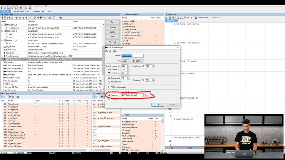
| 11:25 | I'll double click on that and we can have a quick look into some of the details. |
| 11:28 | So in this case we've chosen an output pin here which is able to support up to 25 amps which is way overkill for an electric water pump. |
| 11:37 | Off the top of my head I think this is pulling somewhere in the region of about 12 amps, give or take so well within the capability of that output. |
| 11:48 | When an electric motor like this turns on, there will be an in rush current so initially the current draw momentarily will be a lot higher than its continuous steady state running, in this case we've allowed for a 30 amp in rush current for a period of one second and yeah we've got a maximum current there of 15 amps which is essentially what you consider to be the fusing current. |
| 12:11 | So if the current draw goes above 15 amps it will actually disable that output momentarily. |
| 12:17 | Because it's a power distribution module we've got the ability to retry that output as well after waiting a set period of time. |
| 12:24 | Again, little bit aside from our specific topic but I just wanted to mention how that works. |
| 12:30 | What we're interested in here is the control strategy which is our output here and you can see what I've chosen is to use a channel which is called EWP, electric water pump pulse control. |
| 12:41 | Alright cool let's have a look and see what that function is. |
| 12:45 | And that's what we've got up here, our functions, we've got EWP pulse control so we'll double click on that and dive in a little bit deeper. |
| 12:53 | Now what we've got is a strategy here where we're coming close to replicating what the Davies Craig controller does anyway. |
| 13:02 | So there's a few different modes which we'll just talk about. |
| 13:06 | So first of all here when the engine coolant temperature which is this one here, ECT, is less than or equal to 50°, what we're going to do is pulse this output so it's true for 10 seconds or on for 10 seconds and then off for 30 seconds. |
| 13:24 | So that's just the same or essentially the same as the way the Davies Craig controller does it. |
| 13:30 | So we're turning the pump on for a bit, get some water flowing and then we're turning it off to allow that water to slowly heat up. |
| 13:36 | Difference with this is we are not, we don't have the capability of reducing the voltage the pump is seeing to 6 volts so we are running this at battery voltage. |
| 13:45 | I'll talk about pulse width modulation in a second which kind of has the ability to get that effect but that's our first mode. |
| 13:52 | Then next once we get about 50° we move into our second control strategy here. |
| 13:59 | So we can see that this one is going to become active between 50° and 70°. |
| 14:06 | So when we're in that range, we're going to be on for 10 seconds and off for 10 seconds, again very much replicating the way the Davies Craig controller works. |
| 14:14 | We're a little bit out of order here, this one here is our last stage which is when our engine coolant temperature is above 80°, it's just on all of the time. |
| 14:25 | So it's on 100% duty cycle maximum speed, it's getting a full 14 volts. |
| 14:30 | However before it gets to that, and as I said, again we're a little bit out of order here, we actually move into this one here which occurs between 70° and 80° and in that range it's pulsing on for 5 seconds and off for 1 second so basically we're building up that speed or frequency that it's being pulsed at, the on time versus the off time, until we get up to 80° and then it's on the whole time. |
| 14:55 | This has a very similar effect to the Davies Craig controller in that if we've got sufficient cooling capability and we turn the pump on, the temperature drops down below 80° again, we get back into this stage here where we start that pulsing of the pump again which will have the effect essentially of slowing it down, reducing the flow through the cooling system, through the radiator which should allow everything to heat up so we're again just getting a replication of the way the factory Davies Craig controller works. |
| 15:31 | Now you can tweak these numbers until you're content. |
| 15:35 | In this case we're obviously on above 80°, I'd like to try and maintain low 80° engine coolant temperature in this particular car but you can make these numbers whatever you want to achieve the sort of operating temperatures that you require. |
| 15:51 | Worth mentioning of course, this should go without saying but I will say it anyway. |
| 15:56 | The electric water pump is not a magic device, if you have a radiator that's not up to task, is too small then it's not going to be able to fix a cooling system that's simply not up to the task so you need to make sure that the engineering behind the cooling system is sufficient for your vehicle. |
| 16:17 | Alright so that's our first example there using a very simple switched approach which doesn't require a lot of logic or a lot of technology. |
| 16:27 | We are using a power distribution module for it but shortly we'll see how we could do this directly using an ECU with an auxiliary output. |
| 16:34 | And switching this just with a conventional mechanical relay. |
| 16:39 | Now the other option with, some power distribution modules, including the PMU16 is that they can pulse width modulate the output. |
| 16:49 | And this allows essentially speed control. |
| 16:52 | So we're kind of pulse width modulating the system anyway with the technique I just showed you but at an incredibly incredibly low frequency. |
| 17:02 | So let's have a look at that, we'll go back into our water pump output and we can see we've got our pulse width modulation configuration here. |
| 17:11 | If we click on this, we've got a few options here including our set frequency. |
| 17:16 | So in this case our frequency's 80 Hz, we can adjust this to suit whatever we want to achieve. |
| 17:24 | A lot of the frequency will come down to the device we are controlling and frequency that's too high or too low, you may find you have problems controlling the device. |
| 17:34 | We've got the option here for a soft start. |
| 17:37 | So this is really not necessary for our electric water pump. |
| 17:42 | We are using this for our air compressor for our paddle shift system though and what we find is that, I mentioned with some devices, or with an electric motor, DC motor, when we switch it on we'll get a very high in rush current and with the compressor example that I just mentioned, we're pulling about 18 to 20 amps continuous when the compressor is running. |
| 18:05 | But the in rush current, if we just fully switch it on from stationary, that'll spike to about 80 to 90 amps. |
| 18:11 | Now that's not enough to do any damage because it is only momentary, we're talking a couple of hundred milliseconds at the most but using soft start, what it'll do is initially start at a low frequency and it'll ramp the system up to 100% duty cycle over a period of time, in this case we can see by default that was 150 ms so it just gets us away from that initial in rush current. |
| 18:36 | Now duty cycle control here is what we're going to want. |
| 18:39 | So basically we would set a frequency, maybe 80 to 100 Hz. |
| 18:43 | So that's the frequency the system is operating at and then we want to be able to control the duty cycle because by controlling the duty cycle we will be able to control the speed of the water pump. |
| 18:55 | So we can see, it's asking, what are we going to use to provide the duty cycle control? And we're going to use a function called, or a table called EWP control which we'll look at in a second and that will be 0 to in this case 100 so pretty straightforward. |
| 19:11 | So now the output knows what it's expecting to control it. |
| 19:14 | We'll close that down and we'll come up here to our EWP control. |
| 19:19 | And we've got here a control where we've got our coolant temperature, actually this has been messed with so it's probably not particularly useful. |
| 19:30 | What we would do is set this up with coolant temperature on the axis and the duty cycle as the numbers in that table and then we've got the ability to basically vary the duty cycle being sent to the pump in response to the engine temperature. |
| 19:47 | So let's say the same example we might want to run the pump to between 0 and maybe 30 or 40°C, we might want to run the pump at 10 or 15% duty cycle. |
| 19:59 | So we're going to turn the pump very slowly and that's going to still move the water through the system to allow it to heat up but it's not going to be that effective in terms of cooling. |
| 20:09 | Then above 40°, maybe 40 to 70, we might want to step that frequency, that duty cycle I should say up. |
| 20:16 | We might end up at 40 or 50% duty cycle and then between 70 and our set point target of 80° we're going to step that up so that by the time we're at 80° we're at 100% duty cycle and again that's going to really replicate the operation of that Davies Craig controller and again of course if we've got excess capacity in our cooling system, it should do a pretty good job of maintaining the coolant temperature. |
| 20:42 | Now, I just want to mention here with pulse width modulation with power distribution modules, there are a few caveats with this and this is why a few mainstream manufacturers of power distribution modules actually don't offer pulse with modulation as an option. |
| 21:01 | Seems straightforward, the problem is that pulse width modulation does actually create a lot of heat in the switching transistor that controls that output and if we can't manage that heat, it can end up with that output going into shut down so that is exactly what we found when we were testing the PMU16 with our electric water pump. |
| 21:22 | You can see here again, bring that output up, it's interesting because the output is capable of a continuous 25 amps but even with our situation with the pump drawing a maximum of 12 amps, that just wasn't enough. |
| 21:35 | Post testing though, I did find that if I paired this up, so you can see at the moment this is set up as a single output, we can actually double or triple this. |
| 21:45 | If we use double and we use 225 amp outputs, obviously we need a spare 25 amp output to do it, that gives us the ability for a maximum of 50 amps obviously and that actually did work quite well with the electric water pump so it's just a case of understanding what you're getting yourself in for because of course if you've committed to your wiring outputs and you've wired for the expected current draw, you're then going to, you may find it's quite difficult to come back from that and reverse engineer everything, particularly with a sealed harness like what we'd expect in a race spec application. |
| 22:22 | Alright we've looked at our power distribution module option and two different ways of basically achieving the same aims using the power distribution module. |
| 22:32 | We will move into questions shortly so it's a good time to say if you do have any questions, please start asking those now. |
| 22:40 | Before we do that though I will just show you another example of how we can use a standalone aftermarket ECU and a conventional relay to control the water pump. |
| 22:51 | So in this case we're going to have a look at an example on a Link G4+ but the reality is that you could replicate what I'm going to show you with a little bit of understanding of the way the ECU works on most mainstream brands. |
| 23:08 | What we need to understand with a conventional relay is that they will not operate under pulse width modulated conditions and if we try and operate them on and off too quickly, we're going to get into trouble so we want to be really mindful of that, we don't want to be switching them on and off or trying to switch them on and off at a even a modest frequency. |
| 23:30 | So let's have a look at this, I'm already on the output here which is auxiliary 5 from the ECU which is our, we've labelled it as water pump. |
| 23:39 | Important to understand that all this does is gets wired to the low side control of the relay, 12 volts to the other side, so this is just providing a switch to ground when this output is active. |
| 23:54 | Now it is a little bit complex so I'll just try and explain it as best I can. |
| 23:58 | Obviously, the simple part, its name, it's called a water pump, no big surprises there, pretty important with the Link ECU because if you've got a complex ECU and you haven't seen it for a fair while, this happens all the time when you are tuning profressionally, you set up a car, everything's obviousy fresh on your mind when you do this and you understand everything that you've done and then that car leaves and it comes back in 6 or 12 months time for a touch up or maybe some more modifications and you're looking through the outputs and going what on earth does this do? What was I thinking, why is it set up like this? So this just allows you to add labels to the auxiliary outputs so at a glance we can see alright well this is a water pump, we're not just talking about an auxiliary output called aux 5 and then trying to figure out what on earth that was for. |
| 24:46 | Switch logic, when is the output going to become active? So that is when condition 1, 2, or 3 is true. |
| 24:54 | OK so we've got 3 switching conditions. |
| 24:57 | Interestingly enough, the 3 switching conditions essentially replicate the Davies Craig strategy. |
| 25:02 | So let's have a look at condition 1. |
| 25:04 | This is where things get a little bit trickier. |
| 25:07 | So condition one is based on timer one being true or active and timer one needs to be less than or equal to a value, in this case 10 seconds. |
| 25:19 | OK let's find out in a moment what that actually means but let's jump ahead here, we've got another set up for timer two which really replicates kind of what timer one does so we'll understand that in a moment. |
| 25:29 | And then switch condition 3, in switch condition 3 is the engine coolant temperature is greater than a certain value, that value is being 80°C. |
| 25:39 | So what this will do, our third and final stage here, once our engine coolant temperature reaches 80°C, that output is then true continuous as long as that engine coolant temperature remains above 80°C, hence it will run the electric water pump at a full speed, 14 volts being delivered to it. |
| 25:58 | OK let's dive back into this switching logic and we'll see if we can understand it a little bit more. |
| 26:03 | So let's have a look for a start at timer one and we'll see what timer one is all about. |
| 26:09 | I'll just let this load up, for some reason this software is very slow at the moment on my laptop. |
| 26:16 | OK timer one, it goes a bit deeper here, we'll go further down the rabbit hole because timer one is functioned or activated by virtual auxiliary one, don't worry we'll look at that in a second. |
| 26:28 | And it has a maximum time it'll count up to 40 seconds, 40.0 and then it will reset when it's active. |
| 26:36 | So we know that our timer goes up to 40 seconds. |
| 26:38 | Keep that in mind. |
| 26:40 | And it's being activated by virtual auxiliary one so we of course need to jump into virtual auxiliary one and see what exactly that's doing. |
| 26:48 | Virtual auxiliary one, it's called water pump. |
| 26:51 | Alright little bit deeper here again, so we've got three conditions, looks kind of like our auxiliary output we already looked at. |
| 26:58 | Our condition one is our switch timer, our timer one is greater than a value. |
| 27:02 | In this case 39.990 seconds. |
| 27:06 | Remember it went up to a maximum of 40 before resetting so basically just before it counts out to its maximum, it'll go active so that condition one will become true. |
| 27:15 | Then the other one is RPM has to be greater than 600, in other words we want the engine running so OK if the engine's running and our timer is reset, it's going to become active and then finally our engine coolant temperature needs to be below 50°. |
| 27:29 | So this replicates our warm up area. |
| 27:32 | When we've started the engine and we're just warming it up, our coolant temperature's below 50, this output is going to become active. |
| 27:39 | Now if we go bak to our water pump, now we understand what the timer is doing here. |
| 27:44 | We'll go back to our water pump which I think was aux five. |
| 27:48 | Got there in the end, even if I spelt it wrong. |
| 27:52 | So timer one, now remember timer one reset or had a maximum value of 40 seconds. |
| 27:58 | So it's going to go on when that timer one is less than or equal to 10 seconds. |
| 28:04 | In other words it's going to run for 10 seconds and then it's going to turn off for the remainder of that timer one which goes up to 40 seconds. |
| 28:11 | So it's going to be on for 10, of for 30. |
| 28:14 | It's a slightly less clear and obvious way of doing it but this is because we need to manipulate the ECU's control logic in order to get us the results that we want so in the Link, it ends up being a little bit confusing initially when you're setting it up but hopefully I've gone through that and explained it, timer two of course is essentially exactly the same, just add that next step between 51°C and 79°C and then finally we go up to our full on. |
| 28:45 | Timer two is 10 second timer so that's on for 5 off for 5. |
| 28:50 | So yeah pretty much replicated exactly what we want so you should be able to take essentially what I've just shown there, most ECUs will have the control logic that you'll be able to manipulate in some form in order to get a similar control strategy to what we've just looked at without the need for a power distribution module. |
| 29:10 | Alright we'll jump into our questions and a reminder if you've got any more, keep them coming and we'll see what we've got. |
| 29:17 | Let's have a look at these questions now. |
| 29:20 | Diego has asked, is an electric water pump conversion useful for a daily project car? Look I don't personally think it's an essential. |
| 29:31 | I've kind of gone over the pros and cons, there's definitely some advantages to it but for a daily driven car, if you've got a water pump on the car, mechanical pump on the car that's a known quantity and it's not prone to giving you issues, it's probably a simpler strategy to leave that as it is and as an added bonus it's going to be simpler to plumb and it's also going to be cheaper because you've already got it. |
| 29:57 | Josh has asked, I use an SSR, solid state relay and an EWP 150. |
| 30:02 | I've been curious if there's a way to determine the optimal frequency output for the ECU and the operational window. |
| 30:07 | I know the pump output isn't linear to duty cycle since it's a centrifugal pump. |
| 30:11 | Good question there, I don't know of a way of finding the optimal frequency. |
| 30:17 | I think what we ended up doing was reverse engineering a Davies Craig electric water pump controller with a scope and actually looking at the frequency that was outputting. |
| 30:28 | What you'll generally find though is you're not going to want to be trying to run them at a very high frequency, you're not going to be sort of 500 or 1000 Hz of that nature. |
| 30:38 | It's going to be a relatively low frequency in the range of probably 50 to 150 Hz. |
| 30:44 | What I generally find, the boost control solenoid is a really good example of having a really obvious way of seeing where the solenoid wants to be in terms of the frequency. |
| 30:58 | If you run the boost control solenoid, sorry just try and get my words out here. |
| 31:05 | The boost control solenoid at a frequency that is too low or too high, it'll simply cease operating. |
| 31:12 | It's a mechanical device and it needs to physically be able to move position. |
| 31:16 | This actually normally happens with the boost solenoids at a higher frequency and they just kind of stick in either fully open or fully closed position. |
| 31:24 | So you can probably do the same by actually, before you install the pump, testing it and seeing what sort of relationship you get visibly between the frequency you operate it at and the duty cycle but in my own experience, which admittedly is quite limited with pulse width modulation, they are fairly forgiving so you're not going to have to have an exact frequency in order to get it to work and the most important thing here is irrespective of frequency, we're most worried about what's happening when you're at operating temperature, when you're at 100% duty cycle obviously pretty much irrespective of your frequency, it is operating at 14 volts, your battery voltage so it is working. |
| 32:06 | I will mention though, Josh has pointed out, solid state relay, that is another way of operating this, essentially giving you the ability to pulse width modulate the output which you cannot do with a mechanical relay so yeah that is another option there. |
| 32:24 | Dyno Doug's asked, are there any special water pump considerations for a rear mount radiator setup? Will the OEM mechanical pumps typically do the job or is a more powerful electric water pump often needed? I haven't personally been involved with rear mount radiators, obviously they are pretty common in drift applications. |
| 32:42 | I would imagine that yes as your run of plumbing gets longer, there's simply more restriction to flow so it would be common sense to maybe jump up in size of your electric water pump. |
| 32:57 | I would imagine Davies Craig would be able to advise, or the manufacturers of any of the other pumps on the market would be able to advise on suitability for your application though, I just haven't done it myself so I can't say with 100% certainty sorry. |
| 33:12 | Gormaker's asked, would it make sense to have a really low temperature thermostat in combination with an electric pump to act as a restrictor that keeps coolant in the block until coolant temperature reaches the thermostat opening level but the operative temperature control will be still determined by the ECM water pump? Yes you could do that and the beauty of the thermostat is yes it becomes a restrictor plate essentially which is obviously OE designed and hence correct when it is in its open state. |
| 33:43 | However the alternative to doing that is simply to cut the centre out of the thermostat, that still gives you the outer so you've still got the restriction over the overall flow and then you've got the electric water pump controlling it so I don't really see an advantage or a need to keep the thermostat in the system at all with an electric water pump. |
| 34:06 | Gormaker's also asked, is it preferable to control water pump speed via analog voltage or pulse width modulation. |
| 34:13 | Essentially short of a dropping resistor, pulse width modulation is the way we control the voltage getting to the pump, the water pump and if you actually look at that with something that's slow acting like a conventional digital voltmeter, as you reduce the duty cycle with pulse width modulation, it will read a lower voltage so it's essentially what we are achieving, just as opposed to a dropping resistor, we've got complete control over the voltage that the pump is receiving. |
| 34:48 | Brendan has asked, what about pulse width modulation for a single solid state relay, has anyone tried this and is there any magic, smoke or no worries with a decent heat sink? So yeah again it's not something that I have done, obviously Josh referred to solid state relays and yeah absolutely it is possible. |
| 35:08 | The solid state relay's available in the aftermarket pretty cheap and they normally are large enough that at least as far as I understand, heat for pulse width modulation of a device like this is not a problem so yes you absolutely can go ahead and do that. |
| 35:29 | Another question on a thermostat, do we need a thermostat with an electric water pump on a 4G63? Hopefully the answer should be clear from what I've said so far, no we don't, doesn't matter what the engine is. |
| 35:40 | And we've got another question pretty much the same, maybe some people who missed the start of that, no we don't need the thermostat at all, we're using the water pump control to control the speed and hence that's going to be effective during the warming up stage. |
| 35:56 | Alright that's the end of our questions there so we will leave it there. |
| 35:59 | Thanks to everyone who's joined us and if you are watching this at a later point in our webinar archive, if you do have further questions, please ask them in our forum and I'll be happy to answer them there. |
| 36:10 | Thanks for joining us and we'll see you next time. |
Timestamps
0:00 - Introduction
1:04 - Davies Craig water pump
2:47 - Pierburg water pump
3:39 - Why change to an electric water pump?
5:19 - Thermostat | to remove or not to remove
6:35 - Control strategy | factory controller
10:23 - Control strategy | PMU
22:22 - Control strategy | Aftermarket ECU + conventional relay
29:20 - Questions


