303 | PDM CAN Messaging
Summary
One of the advantages of adding a power distribution module to your project is the flexibility of brining in sensor data as well as on/off requests via CAN messages. The standardisation of CAN messaging also means that we can communicate between different manufacturers ECUs, PDMs and dashes. In this webinar we’ll take a look at how to set up CAN messaging between these devices.
| 00:00 | - Hey team, Andre from High Performance Academy here, welcome to another one of our webinars and today we're going to be diving into the topic of CAN communication. |
| 00:09 | Specifically we're going to be talking about CAN comms when it comes to the installation of a power distribution module, power management unit, call them what you want. |
| 00:19 | And I know that there are a lot of people that are installing these units who get a little bit scared off the idea of CAN communications and basically they simplify the installation dramatically in order to avoid using CAN communications in their particular application. |
| 00:38 | Now there's nothing necessarily wrong with that and yes you can function the outputs from a power distribution module using physical switches, there's absolutely nothing wrong with that but I do feel that first of all, if you go down that route, you are needlessly complicating your installation, it's going to add to your wiring which is one of the reasons we're installing a power distribution module in the first place, to simplify everything and you're really missing out on a lot of the power and potential capability that a power distribution module can give. |
| 01:13 | One of the nice functions as well with the majority of aftermarket power distribution modules is because they incorporate CAN communications, this means that they're essentially brand agnostic. |
| 01:26 | What I mean by this is you can use a Ecumaster power management unit, PMU16 in the case we're going to be looking at, with a MoTeC dash and maybe a Haltech ECU or basically replace those names with any of your favourite brands. |
| 01:42 | As long as the product has a CAN template and can send and receive information via CAN, because it is a standardised protocol, the power distribution module is going to be able to understand those messages. |
| 01:56 | Provided we do understand how to set up communication, so that's going to be the focus of today's lesson. |
| 02:04 | As usual, we will have a question and answer session at the end of the lesson so if there's anything I talk about that maybe you don't understand or anything you'd like me to expand on, please ask those questions in the chat and we'll get to those at the end. |
| 02:16 | So first of all, just a really quick high level refresher on what a power distribution module is. |
| 02:22 | It's simply a way of eliminating the conventional fuses and relays that we always used to run in our cars and instead we run, we rely on solid state electronics to physically switch the power circuitry on and off. |
| 02:37 | So this might be for example, something really simple, the power supply to your fuel pump. |
| 02:43 | Now there's some advantages that come along with this, first of all we've got the ability to monitor the current draw on that particular circuit. |
| 02:52 | Instead of relying on a conventional fuse, we can set electronic fusing limits for that particular output and then most importantly if that particular circuit trips, maybe the fuel pump is getting a little bit tired and the current draw's just creeping up, what we can do is trip it to provide safety to our wiring, making sure we don't overhead and melt anything, then we can wait a period of time and then retry that particular circuit and that, particularly in a race application can be enough for us to get ourselves back to the pits. |
| 03:25 | Alright what we're going to do is just quickly jump across so we can see kind of what that looks like in terms of the inner workings of a power distribution module. |
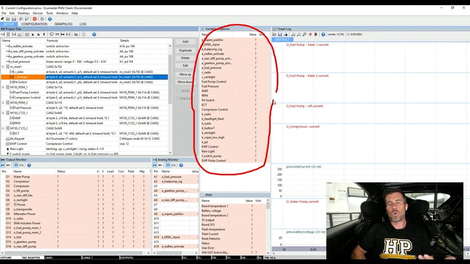
| 03:36 | The worked example, the example we're looking at today I should say is on the Ecumaster PMU16 and that's the PMU client software that we are looking at here. |
| 03:46 | So for example what we're going to be looking at a lot here is our inputs that are coming into the PMU. |
| 03:53 | We've got a range of inputs here, the ones obviously we're focusing on are CAN, don't worry if this makes no sense at the moment, we'll explain all of that as we go. |
| 04:02 | Over here if we were live with this we'd be able to see the real time current draw from any of the outputs that are currently live. |
| 04:11 | And I will mention, had intended to actually run this as a live demonstration, that's why I'm sitting in the car, unfortunately a few last minute technical gremlins meant that we were unable to do that. |
| 04:22 | I do apologise but I don't think it's actually going to take away from today's lesson. |
| 04:26 | Down here in the left hand bottom corner, we've got our output monitor. |
| 04:30 | So we can see our 16 outputs there. |
| 04:33 | We can see the name that we've applied to these so basically what they do, naturally and then again if we were live we've got the ability to monitor the status of that output, whether it's on, whether it's off, the current amps that are being drawn, the voltage that is on that output. |
| 04:51 | We can also monitor things like our peak current as well which is kind of handy because for some aspects, like you can see here on output two and three, we've got a compressor, it's actually two outputs that we've parallelled up to run an air compressor for our paddle shift system. |
| 05:06 | Interestingly, when we switch that on, the peak in rush current actually comes up to about 90 amps. |
| 05:14 | Not particularly uncommon with a DC motor, there will be a high in rush current but the steady state current for that particular output, once it's actually got up to speed and it's running, drops away to 18 to 20 amps so still actually quite a bit but the in rush current is quite dramatic so that's just a quick look at what the inner workings of a power distribution module actually look like in terms of the software. |
| 05:38 | Obviously every product is going to be a little bit different so they all do achieve much the same things though. |
| 05:45 | So I just wanted to talk about the different ways we can activate an output using a PDM. |
| 05:52 | There are a few, one of them in the simplest, which I've already mentioned is physically to wire a switch to your power distribution module and every PDM gives you that option. |
| 06:07 | So this way we can use an existing switch that you may already have on your dash and you can turn things on and off using that switch. |
| 06:14 | Alternatively let's say we've got an ECU that wants to turn the fuel pump on. |
| 06:20 | Well conventionally with a relay and a fuse, what we would do is configure an auxiliary output from the ECU to provide a low side switch to a relay, it would trigger that relay because the ECU itself can't handle the current that the fuel pump is going to actually pull. |
| 06:37 | Fuel pump might be in the order of 12 to 16 amps for example, circuitry inside of the ECU's really probably only good to handle a few hundred milliamps so that's why we use the relay as an interim. |
| 06:49 | So basically it's just using the ECU to switch a high current switching device that's our relay. |
| 06:56 | So we can still use that system with a power distribution module, instead of wiring that auxiliary output from the ECU to the relay, we then just run it to the power distribution module, essentially it becomes the same as having our dash mounted switch, configure it in the software, job done. |
| 07:13 | Now it'll work but as I've kind of alluded to here, we're making more work for ourselves at the wiring side than is necessary. |
| 07:22 | Instead of sending that signal to turn the fuel pump on through a physical wire, we can send it via a CAN message and that's what we're going to be looking at today. |
| 07:32 | The other aspect we can use, we can get quite clever with these PDMs, we could switch an output based on conditions. |
| 07:40 | So let's say for an example with this particular car, we have a pit switch. |
| 07:47 | So that's triggered off the steering wheel. |
| 07:50 | I'll just bring the steering wheel into sight here. |
| 07:52 | And our pit switch is up here on the top left side of the steering wheel. |
| 07:58 | So that's actually a latching input, latching switch. |
| 08:02 | So once we click it, it stays latched, you click it again to turn it off. |
| 08:05 | So we use that pit switch for a few purposes. |
| 08:09 | First of all inside of the ECU it brings in a 40 km/h speed limiter because we do have a pit speed limit here in New Zealand. |
| 08:17 | if we get caught exceeding that speed limit, we end up with a drive through penalty or time added to us so we don't want that. |
| 08:24 | At the same time though we're also using that pit switch to bring up a driver warning on the dash, not really strictly related to our PDM discussion but just worth mentioning. |
| 08:36 | However as far as the PDM's concerned, when that pit limit switch is active, a signal goes through to the power distribution module and what that does is irrespective of engine temperature, it will run the cooling fans. |
| 08:50 | And that's because when we come into the pits, technically or most often we're going to be coming to a stop. |
| 08:56 | Now yes the fans will switch on based on temperature as well but this just allows the fans to essentially come in a little bit sooner, as soon as we're on that pit limit and this can help reduce or avoid some of the potential pitfalls with heat soak that could occur if we weren't doing that. |
| 09:13 | So beyond this we could bring in a sensor directly to the power distribution module, let's say we've got a conventional carburetted engine that doesn't have sensors like engine coolant temperature, because it doesn't have an ECU. |
| 09:29 | No problem, we could bring in a negative temperature coefficient thermistor for engine coolant temperature, wire that direct to the PDM, we could then configure it in the power distribution module and then set up a function in the PDM to then trigger the fan based on that coolant temperature. |
| 09:46 | So I'm hoping you're getting the idea here, there's a few different ways of approaching this and there's no right or wrong way, really comes down to what you're trying to achieve and what you're actually working with in the first place as to what's going to be the best option. |
| 10:02 | OK moving on, I'll give you a quick overview of the electronics configuration of this car because it is somewhat complex although not too far fetched and probably not out of the ballpark of modern racecars that are set up with power distribution modules. |
| 10:20 | So first of all we've got the engine management system which is the MoTeC M150 ECU and we've got the coupled with a MoTeC C125 which is the dash logger and display so that functions primarily as our central logging hub as well as a driver display. |
| 10:38 | Now on top of that we have in this instance two Ecumaster PMU16s. |
| 10:43 | One single 16 channel PMU was not enough to basically handle all of the control outputs for this particular vehicle and that would be pretty typical with most, even semi complex vehicles, doesn't take long to chew through 16 output channels. |
| 11:02 | One of the advantages with using multiple power distribution modules is that we can fit one at the front of the vehicle and one at the rear. |
| 11:12 | So for example, we can separate the power outputs for things at the back of the car like our fuel pumps, maybe our tail lights. |
| 11:21 | In this case we've got a oil pump for our differential, we've also got a cooler for our diff pump as well so all of this stuff that's at the back of the car can be handled off that rear PMU, stuff at the front of the car can be handled off the front PMU. |
| 11:37 | And that again can help simplify our wiring, simplify our layout and then really all we need to do is communicate between the two PMUs or our electronic modules using CAN which obviously again is the focus of our discussion here. |
| 11:52 | Now on top of that, we also have a couple of other units. |
| 11:55 | We do have, it's probably going to be a little bit hard to see here, on the back of our steering wheel, we've got an Ecumaster CAN switchpad. |
| 12:03 | Now the reason we've got that is because it converts all of the switches as well as these rotary switches on the front of the steering wheel into CAN messages. |
| 12:12 | And that's handy because this curly cord that runs from the steering wheel through to the body of the car, if you've got a bunch of switches, it's going to get complex, you're going to have a lot of wiring running through. |
| 12:26 | In our case we only have 4 wires. |
| 12:28 | 12 volts, earth, CAN high and CAN low. |
| 12:30 | So a great way of simplifying all of that information. |
| 12:36 | So that's communicating with a variety of our pieces of electronics. |
| 12:40 | We're communicating directly with the Ecumaster PMUs as well as to our MoTeC C125 dash. |
| 12:47 | We can't send data directly from the CAN switchpad to the MoTeC ECU because the format is not something the M150 ECU is expecting so that's why we're using the C125 dash, kind of works as a bit of a gateway so we're taking the information into the dash, converting it into a signal that the M150 ECU can understand and is expecting and then sending it out again. |
| 13:13 | So I know this is all getting a little bit complex but bear with me, it's all going to make sense as we go through. |
| 13:18 | Last product which I can't turn the camera around and show you is we've got the pretty common Blink Marine 8 button CAN keypad as well. |
| 13:29 | And it's really easy to integrate these with the Ecumaster PMU so we can use that CAN keypad for functioning just about anything on the PMU and again just like the CAN switchpad on the back of the steering wheel, these CAN keypads only require 12 volts, earth, CAN high and CAN low so hopefully at this stage, you're starting to see how much it simplifies that wiring rather than having the wires required for 8 individual switches running up to our dash. |
| 13:58 | OK so I know again it has been a little bit confusing and there's a lot of stuff going on here, a lot of moving parts but what we're going to do is start by looking at something really really simple which I've already covered off briefly which is our fuel pump control. |
| 14:15 | So I mentioned we could hardwire that but of course that's not what we want to do so let's see how we've got that done. |
| 14:21 | So first of all we'll dive back into my laptop screen here and what I've done here is we'll come across to the all calibrate worksheet and I've just typed in fuel pump here. |
| 14:31 | So this brings up all the information relevant to our fuel pump and what we're really interested in here is this particular piece of information here which is our fuel pump resource which is simply MoTeC M1 lingo for what output are we going to use to request that fuel pump to switch on and off? Now what you can see here is in that drop down menu, open that menu up, you can see we've got all of the usual outputs that we could expect, we've got half bridge outputs that are free, peak and hold, injectors, as well as low side ignition. |
| 15:03 | And then we get into our PDM output. |
| 15:06 | So in this case it is being sent as a message, a CAN message on PDM byte 0, mask 01. |
| 15:13 | Now that's a little bit obscure I'll admit. |
| 15:17 | So what we can do here is just look at how this works, how the PDM works. |
| 15:22 | So if we come across to the vehicle worksheet which I'm already on, work book I should say, and then we come across to communications. |
| 15:32 | This shows all of the communications to and from the MoTeC ECU and if we come down here, what we can see is we've got our PDM setup. |
| 15:42 | So couple of pieces of information here. |
| 15:45 | First of all, what CAN bus is the ECU going to communicate to the PDM on? In this case CAN bus 1, the M150 ECU has, off the top of my head, 3 CAN buses. |
| 15:57 | Fact check that, anyway we're on CAN bus 1 so that's the CAN bus we know we need to be wired between the ECU and the PMU. |
| 16:05 | If that's not wired up, it's not going to work no matter what we do from here. |
| 16:09 | Then we can also choose a base ID, base address for the PDM messages which in this case is hexadecimal 0500. |
| 16:20 | Basically what we want to choose here is an address that isn't going to conflict with any other messages that are floating around on the CAN bus. |
| 16:27 | That's the important part there. |
| 16:30 | Now also just so you can see this as well, if I can check here, under ECU transmit in the help, I'm just showing you this so you can find this. |
| 16:43 | This shows what information is sent out on the PDM messages and particularly here, it shows how the PDM byte and mask are transmitted as well as a range of other messages that are already transmitted naturally so for example you can see that engine speed, throttle position, coolant temperature, oil temperature, fuel temperature, etc are all transmitted naturally so if we simply set up a receive template in the PMU, we can function let's say a thermofan based on our coolant temperature. |
| 17:23 | We could function our differential cooler pump or our transmission cooler pump based on the temperatures of those two fluids. |
| 17:31 | So all of that information is in there. |
| 17:35 | So just show you how to get to that. |
| 17:37 | Anyway, coming back to our all calibrate here and we already know that our information that we want here, our request for our fuel pump is being sent out on that PDM byte 0 mask 01 because this is just a single bit that's changing between low and high. |
| 17:53 | So that's the mask element of that and it is on byte 0, we already know the base address. |
| 17:58 | So let's head back over to our PMU and we'll see what that looks like. |
| 18:03 | Alright bunch of information going on here, but again don't be scared too much by this. |
| 18:08 | So we've got first of all, this particular point here is where we have configured out CAN receive message. |
| 18:16 | I've called this M150 PDM1 and we can see that we've configured what CAN bus this is on. |
| 18:25 | OK this seems confusing right, I already said that the M150's working on CAN 1, now we've got CAN bus 2 so what's going on here? Simply put, the M150 has 3 CAN buses, the PMU16 has two. |
| 18:39 | We're just saying which CAN bus we connected the ECU's CAN bus to. |
| 18:44 | So I know a little confusing. |
| 18:46 | CAN bus 1 on the ECU is wired to CAN bus 2 on the PMU. |
| 18:50 | So just physically where have we wired that, it's not as complex as it seems there. |
| 18:56 | Then we've got our base identifier here in hexadecimal, basically where abouts we're going to be finding that particular message, where we're going to be looking for it. |
| 19:05 | So that's just the base address for our PDM messages, so we can close that down. |
| 19:10 | Then underneath that though we've got two specific messages that we are going to be using for control, our fuel pump control here, we'll click on that, we've given that the name there fuel pump control of course. |
| 19:24 | We are using the message object that we just talked about, PDM1. |
| 19:29 | And then we can configure what we're actually looking for here in terms of the bit that we want to extract. |
| 19:38 | In this case we're looking to extract bit field, the bit count is 1 and the bit position is 0. |
| 19:45 | Now again I wish I was live with this because one of the really nice features with the PMU16 is that when we are live, we can actually see exactly what data is coming through on that particular address. |
| 20:00 | So what we essentially can do there is test and make sure that when we request the fuel pump, that the particular bit that we're extracting is actually going between 0 and 1. |
| 20:11 | What we should see here is our result which is a bunch of question marks at the moment, that goes from 0 to 1 when the ECU requests the fuel pump. |
| 20:19 | If that's what's working then we've done our job correctly, we're now correctly extracting that request for our fuel pump and the fuel pumps will be able to function. |
| 20:29 | So that's our first element there. |
| 20:33 | Now that's not enough necessarily just to run our fuel pumps though. |
| 20:37 | If we come down to our outputs down here, we've actually got a couple of fuel pumps but if we look at our fuel pump main one, we'll have a look and see how that is set up and that output there is based on that function fuel pump control that we just looked at. |
| 20:53 | So in other words, to cut this down and make it nice and simple, the ECU is going to send out a fuel pump request on that PDM message that we just looked at. |
| 21:04 | We're now decoding that inside of the PMU, we're extracting the single bit that's going to change from low to high when the request is active. |
| 21:14 | Once we've extracted that and we test it and we know that it's correct, then we can use that to turn on our fuel pumps. |
| 21:22 | So job done. |
| 21:24 | So this is probably one of the simpler elements. |
| 21:27 | While we're here, we've got another element here which is our compressor control. |
| 21:31 | So this is for our compressed air pump for our paddle shift system. |
| 21:37 | So again that's being monitored by the MoTeC ECU. |
| 21:42 | I'll see if I can easily show that as well. |
| 21:46 | Compressor, I can't actually quite remember what that is called. |
| 21:50 | Shift actuator maybe. |
| 22:00 | Got there in the end, shift actuator pump. |
| 22:03 | Again one of the things with working with MoTeC M1 is it is very very specific about the language is uses so you do tend to start learning what a particular output is. |
| 22:14 | Until you do that it can be a little bit frustrating because physically finding a particular function or channel or output that you're looking for in what is a very complex ECU can be quite time consuming. |
| 22:26 | So this is called our gear shift actuator pump. |
| 22:30 | So makes sense when you actually sort of think about it. |
| 22:33 | And again we've got exactly the same thing here, we've got our relay output resource. |
| 22:37 | Note it says relay here but obviously we're not dealing with a relay. |
| 22:41 | Again we could configure this as a conventional switched output but we're using PDM byte 0 mask 02 so remember last time it was mask 01, this time 02. |
| 22:53 | Now we've got some aspects here for the actual control so this is why it's important because we're actually controlling within the ECU when the compressor will switch on and off. |
| 23:03 | So it will switch on until we reach 850 kPa and then it'll switch off once the pressure drops by the hysteresis amount, in this case 100 kPa, it'll switch back on. |
| 23:13 | So head back into our PMU and we can see that our extract there, we're extracting in this case bit position 1 based on that mask again we would be able to watch exactly what's happening in live data and realistically again we're just looking for our result there when the compressor request comes through, is that switching from a 0 to a 1. |
| 23:37 | Job done so exactly the same as setting up our fuel pump control. |
| 23:40 | It is relatively straightforward. |
| 23:42 | Once we have an understanding of how to decode the PDM messages that we've just looked at. |
| 23:49 | Now you can also use that, sorry before we jump into that, I'll just jump down to our actual compressor channels. |
| 23:56 | You can see again I've got, this is doubled up because even despite the fact that the pump is pulling less than the 25 amps for this particular channel, we found that we had some issues with the overheating of that circuit when we were using a single output. |
| 24:15 | So really easy there, this is just functioned purely on the channel compressor control which we know we've just looked at and we've just set up so pretty easy. |
| 24:25 | Now you can use exactly the same functionality there to set up your thermofans or basically anything that you would conventionally run from the ECU as an auxiliary output and a switched output so pretty easy to really go through and set this up and again, save yourself a bunch of time and effort with your writing and simplify your whole installation. |
| 24:48 | The only real key here is a little bit of an understanding of CAN as well as making sure that you thoroughly test this and ensure that you are in fact extracting the correct bit and that it is going active and turning off when you expect it to. |
| 25:04 | It's very easy to sometimes have something that's a bit of a coincidence and you think it's working how you want and then you get another combination of situations where all of a sudden that output is not functioning so thorough testing is really really important when you're extracting a single bit like that, making sure that you have in fact got that correct. |
| 25:24 | Alright we'll now look at our CAN keypad and this is very much specific to the power distribution module manufacturer so in this case relatively straightforward because this is all designed to be plug and play. |
| 25:42 | So if we scroll down here in our software and we have our CAN keypad that is listed here, and we double click on this, it'll bring up our functions. |
| 25:53 | So we can give it a name here and we can set up basically which CAN bus this is on and then we can set up what each of the functions here on the CAN keypad is going to do so really really easy to basically make one of these CAN keypads do whatever you want. |
| 26:13 | Whether it's to do a master power on and off, starter motor engagement or you can use it for setting your fans on and off, just about anything else you could imagine, basically once you set one of these up it just brings it in simply as a function which you can then use to control your output. |
| 26:32 | So nothing particularly special there, no requirement to do any special CAN messaging, it is just a setup that is designed to work within the PMU16 by default so really simply and pretty much a no brainer to incorporate one of those, again to simplify the functionality in your wiring and you can also incorporate the ability to change colours on the CAN keypad to indicate at a glance what the function is set to at a particular time. |
| 27:06 | Now we'll have a look at some of the more complex functionality that we've got going on in here and what we'll do is start by having a look at our CAN switchpad. |
| 27:16 | So I know it sounds confusing, we've got a CAN keypad, the CAN switchpad if you'll remember, that's this little guy sitting on the back of the steering wheel. |
| 27:24 | So we've got that as I mentioned going to a couple of locations and we'll start just by having a look at that inside our MoTeC C125 dash manager. |
| 27:34 | So if we come up to connections and come down to communications, this will show us all of the CAN comms that we've got going on and there is a lot of stuff going on in here, in particular you can see we've got some Izze Racing tyre temperature and pressure monitoring inputs coming through but the main ones that we're really interested in here are some custom templates that we've written here for our Ecumaster switch panel, we've got 1 and 2, we can click on those. |
| 28:00 | In this particular one we've got traction control and launch control coming in. |
| 28:04 | We're using that for driver displays, we can then display the position of those two inputs up on the dash. |
| 28:11 | We've got our CAN switch panel 2, that's bringing in a couple of their non descript, general purpose numbers, so we're using those for the likes of our pit switch for example, that's just a general purpose input. |
| 28:28 | We've got a push to pass button which is going through to the ECU as well as our gear shift paddles up and down because the paddle shift here, those switches from the paddles actually go into the CAN keypad and the paddle shift is functioned via a CAN message. |
| 28:43 | OK so that's the switchpad going into the dash and then in turn that transmits out the information in a message that the MoTeC ECU can understand in this M1 transmit. |
| 29:00 | So here we've got ou launch control, traction control, GP output which is our pit limit, probably should actually edit that and name it something so that I don't struggle to remember what it is. |
| 29:11 | We've got our boost limit disable which is our push to pass button and our gear shift up and down. |
| 29:17 | So that's all aside from the PMU so this is why I wanted to show you this is just to sort of demonstrate the fact that the flexibility here, we've got the same component that CAN switchpad is sending messages to multiple locations, it's going into the dash and in turn going into the ECU but at the same time we've got those same messages also being received by the PMU16. |
| 29:38 | Essentially that data is just out there on the CAN bus and any device that needs that information can just grab it and understand it, provided it has a receive template that is written to suit. |
| 29:50 | Let's head back into our PMU16 and see what we've got in here. |
| 29:54 | Alright so we can come up here a little bit and this particular message here is where we are receiving the relevant information for our CAN switchpad. |
| 30:07 | So again much like the setup that we already looked at for the PDM messages, we'll double click on our message object for the moment and we can see that again it's coming in on CAN bus 2 and in this case the base address is hexadecimal No problem, that's just where we're going to be looking for that particular message. |
| 30:32 | Now the actual information that we want in this case, we've got our radio button, we've got our rain light and we've got our pit switch. |
| 30:41 | So let's have a quick look at our pit switch for example. |
| 30:44 | And we can see where we're getting that from, which message object we're getting that from and again we're just on the base address there. |
| 30:53 | The data format there, we're looking at in this case a byte offset of 4 and we are looking for bit position 6. |
| 31:04 | So that just extracts that particular bit, again we can use the live information down here to let us know what's going on and it's as simple as basically turning the pit switch on and off and watching to see what data is changing, then extracting the relevant bit. |
| 31:22 | So that's our pit switch there, reason we're using that again is to function our radiator fans, we don't really need the PMU specifically to do anything around the actual pit speed limit but again we are using that for a separate function. |
| 31:37 | If we look at our rain light here, very similar there with how the rain light works. |
| 31:44 | Just a different position that we are extracting that particular bit of information from and the other thing I should have actually mentioned here as well when we are live, our variables inspector, that will let us see the current data or status of any of the information that we've just looked at. |
| 32:04 | So for example, we just looked at our rain light, we've looked at fuel pump control, we can see whether those are active or inactive at any particular time. |
| 32:14 | Shortly we'll have a quick look at manifold pressure and RPM and we'll obviously be able to see if those are correct as well. |
| 32:22 | Now in terms of our rain light, if we look at our output here, that's output 6. |
| 32:31 | So we've got a couple of aspects here, and this is again some of the flexibility that comes with a power distribution module. |
| 32:38 | We are functioning this, first of all, if the rain light function is active. |
| 32:44 | So if we've pressed the rain light, we're going to flash the rain light and it's going to flash on and off, on for 0.2 of a second and off for 0.2 of a second but I'm also going to be using that rain light when we are in the pit lane, so when our pit switch is on, that rain light will flash on and off, little bit slower this time just to distinguish, half a second on, half a second off but obviously you can do pretty much as you wish with that. |
| 33:11 | I think that probably pretty much covers our aspects there but really it's the same situation, set up a receive message or a message object based on the CAN bus and the address that that message is going to be received on and then we can set up individual messages that we want to extract from that particular CAN ID and then we can use those to function our outputs as we see fit. |
| 33:41 | Last thing I want to look at here and we'll go into some questions and answers once we've looked at this so good time to get those questions in now, is bringing sensor information in. |
| 33:53 | So in this case if we look over on the left hand side here, we've got our message object here which is M150, C125 1. |
| 34:06 | So this is just a standard message that the M150 sends out. |
| 34:11 | Conventionally we'd use this and receive it into the MoTeC C125 dash so straight away we've got all of the important information that we want. |
| 34:20 | So let's quickly head over to our C125 dash and we'll head back up to the top. |
| 34:25 | So this is the particular message here, it's on address hexadecimal 0640 and what we can see here is a list of all of the channels that are being sent through. |
| 34:39 | Engine RPM right at the top which is important because we'll look at that but we can scroll down, there's a huge amount of data coming through here, some relevant to us, some unticked and not relevant. |
| 34:52 | Obviously not too concerned about our knock trims on cylinders that we don't have on a 4 cylinder engine. |
| 34:58 | Alright so that's the data and again we don't have to do any hard work here, the MoTeC M150 ECU will transmit this by default if we want it to. |
| 35:07 | Alright let's head back into our PMU16. |
| 35:12 | So let's have a look at that message object. |
| 35:15 | And again CAN bus that we're on and the address, we've already just looked at the dash software and we know that we're looking at hexadecimal 640 and as usual we are on CAN bus 2. |
| 35:26 | I'm using the other CAN bus, CAN bus 1 as a PMU to PMU CAN bus there so not really too relevant for our conversation. |
| 35:36 | So let's look at our, we've got RPM, we've got manifold pressure coming through. |
| 35:39 | Let's look at our RPM message and this is pretty straightforward here, we are bringing this in from that particular message object and it is on our base address. |
| 35:50 | We've got all of the information about the location. |
| 35:55 | So this is the first piece of information. |
| 35:57 | So hence the byte offset there is 0, we can go back over and see this. |
| 36:06 | And if we look at our receive channels and we click change, our byte offset here is 0, so it matches typically with MoTeC by default, all of the information is sent out via a 2 byte message so the length of the message is 2 bytes and the offset is 0, so that matches what we've got in the PMU set up here. |
| 36:31 | And then we can apply some scaling as required, in this case we don't need to so our multiplier, diviser and offset are all set to 1, multiplier and diviser I should say are set to 1, offset is 0 and again what we were able to do here is view the actual information that is coming through and of course all we need to do is have the engine idling and we should be able to see that the RPM does in fact match what we're expecting. |
| 36:58 | So why would we want to bring RPM in, I mean there could be 100 different reasons, maybe we want to instigate an anti stall function based on clutch position, obviously we'd need clutch position as part of that and the engine RPM so we could use that as part of a more complex function. |
| 37:18 | Again really there's no right or wrong way of using these, it really just comes down to your own imagination of what you're trying to achieve. |
| 37:27 | The other piece of information we've got coming in here is on a different message. |
| 37:32 | Which is our M150 C125 2 an that's on a different CAN address, in this case 649 and we've got our engine coolant temperature, obviously pretty self explanatory why we may want to bring that in. |
| 37:45 | Now if we look at this, again it comes down to multiple ways of achieving an output or an outcome I should say. |
| 37:54 | So if we're looking at thermofans we could switch these simply based on the ECU's thermofan request. |
| 38:01 | We already know that that's going to come through as a PDM message. |
| 38:06 | So that's one way. |
| 38:07 | We could however extract, like we've just done here, engine coolant temperature as an actual sensor input and then we could write a function within the PMU16 to then turn on our radiator fans based on the coolant temperature and some hysteresis etc. |
| 38:24 | Or as we've already looked at as well, we could use another function to bring that in such as our pit switch so again multiple ways to achieve a specific outcome. |
| 38:34 | Alright hopefully so far everyone hasn't fallen asleep and hopefully this has made some sense. |
| 38:40 | I will jump into our questions now and have a look and see what we've got. |
| 38:45 | A good time to mention if you've got more questions, keep them coming. |
| 38:49 | What I will also mention is obviously we've gone a little bit deep on the CAN stuff here. |
| 38:56 | I do know that this isn't something that is familiar to everyone, particularly those just starting out, even some experienced professional tuners do struggle a little bit with CAN and I will just mention here, if you do want a deeper understanding of CAN, we do have our understanding CAN or CAN decoded course that is available. |
| 39:17 | You can find that at hpacademy.com/courses. |
| 39:20 | And Zac does an amazing job of explaining how CAN works, the makeup of a CAN message, how to understand what it's actually doing and how to decode CAN messages, how to write CAN templates as well so it's a really good place to get started if CAN at this stage is just maybe a little bit beyond you. |
| 39:41 | Alright first question comes from Chase who's asked, is it ideal to hook up brake, turn, headlight, wiper switches etc to one of those CAN converter boards that was on the steering wheel as well? I'm assuming the PMUs have limited analog switch inputs? Chase, I mean this is another situation where it's really a bit of personal preference. |
| 39:58 | You are right though, every power distribution module's going to have a relatively limited number of resources in terms of analog or digital inputs so you do need to be a little bit mindfiul. |
| 40:10 | Yes using something like a CAN switchpad is a really really good way of simplifying your wiring and we're going through exactly this with my FJ40 project at the moment. |
| 40:20 | We're keeping the conventional analog switches on the dash, just to give it the original look and feel. |
| 40:27 | But behind the scenes those are simply getting wired into an Ecumaster CAN switchpad and then we'll send those messages out so simplifying the wiring whilst still achieving the authentic look that we wanted. |
| 40:39 | Obviously that's not necessarily an important consideration for every project but just goes to show how you can utilise those. |
| 40:48 | Allan has asked, can it be set to do pulse width modulation functions? Good question Allan and the answer is yes, the PMU16 does actually provide pulse width modulation as well as soft start functionality. |
| 41:01 | A word of caution here from my own personal experience. |
| 41:05 | Now one of the reasons why not every power distribution module on the market offers pulse width modulation is that when we pulse width modulate an output, for those who don't know what I'm talking about here, it's essentially speed controlling an output so think of it like instead of an on/off switch, we're now adding a dimmer switch to a light. |
| 41:27 | So we can control everywhere from completely off through to fully on as opposed to just off and on. |
| 41:34 | Now the downside when we do this, when we're pulse width modulating is it creates heat on the transistor that is switching that output and we found at least with our PMU16, pulse width modulation control of our Davies Craig electric water pump was enough to relatively quickly put the output into thermal overload and shut down. |
| 41:56 | What I would suggest is if you are considering using pulse width modulation, dummy wire the output quickly and dirtily up and test it to make sure it's going to work as you expect it before committing to wiring. |
| 42:10 | We found with the electric water pump, we would have required to outputs parallel in order to adequately pulse width modulate that so just a word of warning there. |
| 42:21 | Manitou Black's asked, for simplicity, would you recommend staying wanting an OEM ecosystem, say all ECM, oh staying within an OEM's ecosystem, say all Ecumaster products, or MoTeC? Honestly no. |
| 42:38 | Years ago I probably would have said yeah it's probably a good idea. |
| 42:41 | These days we mix and match all the time and I mean this car is a testament to this. |
| 42:45 | We try and stay relatively brand agnostic. |
| 42:48 | We are using the MoTeC M150 ECU primarily because their Toyota 86 engine swap package just makes it an absolute dream to run this car and keeping aspects like the factory ABS, electric power steering is difficult if not impossible with a conventional standalone ECU but again as I mentioned during the lesson itself, because CAN is a standardised protocol, as long as you're using products that have flexible receive and transmit templates, there's absolutely no reason not to mix and match componentry, no real downsides. |
| 43:27 | What you're also finding these days is because manufacturers of these products also know that we are mixing and matching, they actually go to quite a lot of length to make our life a little bit easier. |
| 43:39 | So good example of this is the Plex LCD, sorry OLED CAN display. |
| 43:47 | A little off topic for the product but then important point here is you can use this as an auxiliary display. |
| 43:53 | That comes with pre configured CAN templates that you can select for just about every mainstream ECU that you're likely to come across so from the end user's perspective, no real requirement to understand CAN, just simply select the electronics components you're using from the drop down menu, job done and it'll work. |
| 44:16 | Second question from Manitou Black, does a product like the Haltech Nexus simplify vehicle integration versus a mutli component solution, assuming you're not input and output limited? I'll refrain from giving a complete answer on this simply because I am not at this stage in a position where I have tested the Nexus R5 myself. |
| 44:36 | However looking at the spec sheet and talking to a few who have, I would be very sceptical of your ability to complete an entire car wiring system using just the R5 unless it was an incredibly basic vehicle. |
| 44:52 | Basically, and this is understandable, the outputs available from the Nexus' PDM, there's just simply not enough to run all of the engine functionality or circuits that you need to provide power to as well as everything else that's in the car such as windscreen wipers, headlights, tail lights, fuel pumps, thermofans. |
| 45:13 | You probably get pretty close but again unless it was a very very stripped out basic setup, I would doubt that you would be able to complete the entire setup. |
| 45:22 | Hence you're probably still going to need an auxiliary product anyway. |
| 45:25 | Chase has asked, can you set up a momentary switch to cycle through options? Or does the input need to be a discrete multi position rotary switch? I.e. dash display screens, traction control? No absolutely you can set up a momentary switch, you can set that up to cycle through and you will set a low number and a high number and basically whether it's going to step up to the highest point and then start back from 0 or whether it's going to step up and then step back down. |
| 45:54 | A huge amount of flexibility around that and particularly for changing dash display screens, we wouldn't necessarily want a multi position switch for something so simple. |
| 46:04 | A single button is more than sufficient. |
| 46:07 | I like the traction control and boost control multi position switches but that's again not the only way to address that, it's more of a personal preference thing than anything. |
| 46:18 | Alright team that looks like all of the questions we've got, some great ones in there so thanks to those who have contributed and remember if you are watching this at a later point in our archive and you've got further questions, please ask those on the forum and I'll be more than happy to answer them there. |
| 46:31 | Thanks for joining us and hopefully we can see you again next time. |
Timestamps
0:00 - Introduction
2:16 - What is a PDM?
3:25 - Software overview
5:45 - Activating PDM outputs | Wired switches
7:22 - Activating PDM outputs | CAN messages
7:33 - Activating PDM outputs | Custom functions based on inputs or CAN messages
10:02 - Overview of electronics in our GT86
13:58 - Fuel pump control
21:27 - Compressor control
25:25 - CAN keypad
27:05 - CAN switchpad
33:42 - Bringing sensors in via CAN
39:41 - Questions


