312 | Switched Cam Control — Emtron
Summary
In this webinar we’ll investigate some of the options available to control a switched cam engine such as Honda’s VTEC system using the Emtron SL4 ECU.
| 00:00 | - Hey team, Andre from High Performance Academy here, welcome to another one of our webinars and this time we're going to be diving into some of the control strategies or tuning strategies available for switch cam control systems. |
| 00:13 | Specifically we're going to be looking at how this is being done using an Emtron SL4 ECU. |
| 00:20 | It's applicable to the entire range of Emtron ECUs though and we're going to be looking at this on a Honda K20 naturally aspirated engine. |
| 00:30 | This is fitted to our Honda CRX and I'll just quickly head over to my laptop screen and just show you the car. |
| 00:38 | This is a recent new addition to the HPA garage so this is the car, it is a early 90s EF chassis CRX. |
| 00:48 | Benefit of this particular chassis, it is incredibly light, around about 900 kg. |
| 00:52 | This is the engine fitted into it, it's a pretty tight fit into the EF engine bay. |
| 00:59 | Particularly given that the K series is quite a tall engine. |
| 01:03 | This is a built K20, it's running a fairly mild combination with high compression pistons, it's got a set of stronger connecting rods, a CNC ported head, larger valves and a set of aftermarket cams. |
| 01:17 | So nothing particularly crazy there, however it is producing around about 193 kW at the front wheels. |
| 01:24 | So it is a pretty healthy combination. |
| 01:27 | However what we're going to be talking about will be relevant to just about any switched cam control engine regardless whether it's modified or standard. |
| 01:37 | And on that note, we really need to start by talking about what I'm meaning by switched cam control and there's always a little bit of confusion here because we also have variable cam control engines and some people mix and match the terminology. |
| 01:51 | What I'm talking about with switched cam control is something like Honda's VTEC systems, Toyota use VTC, Nissan have their own system and this is a system where we are either switching between cam lobes, so obviously in the Honda VTEC system, we have 3 cam lobes. |
| 02:11 | Two of them run directly on the rollers and basically run the, open these valves and close the valves at lower engine speeds and then hydraulically actuated at the switchover point, the bigger lobe in the middle will be locked in and then that operates both valves. |
| 02:29 | So the idea of course is that it gives us essentially the best of both worlds where we've got a cam profile that's optimised for low RPM performance and low emissions, good drivability but we've also got a large more aggressive cam lobe offering more lift and more duration that's more optimised for high RPM performance. |
| 02:49 | So that is one style of switched cam control system. |
| 02:53 | However there are other options, the likes of Nissan and Toyota have utilised, Toyota on the 4AGE for example had a switched cam timing system. |
| 03:05 | So this didn't use the multiple lobes, instead what it had was a cam wheel that could be advanced and retarded by filling it with oil. |
| 03:16 | Now this is starting to get where the confusion comes in because that strategy that I've just talked about is very very close to the modern continuously variable cam control system. |
| 03:27 | But the difference is with the likes of that system from Toyota, there is no control of it in between the limits, it's either at the full advanced position or the full retarded position. |
| 03:39 | It's not being pulse width modulated, there's no feedback on cam position, it's just either fully advanced or fully retarded so we control that style of system exactly the same way as we control the VTEC mechanism, it is just physically switching over from one position to the other at a point that we choose. |
| 04:00 | The other type of system though, continuously variable cam control, where another bit of confusion comes in, the Honda K20 has this as well, this is why they call it iVTEC. |
| 04:11 | So it has continuously variable cam control on the inlet cam only and then it has the VTEC mechanism on both the intake and exhaust cam. |
| 04:19 | So little bit of potential for confusion, the continuously variable cam control, we're not touching on further, it does require a specific control strategy and it also requires a cam position sensor so that we actually know where abouts the cam is between its full advance and full retard limits. |
| 04:38 | Alright so enough of that, let's talk more about our switched cam control and what the issues are that this causes. |
| 04:49 | So the main one really is that when we switch from our low cam profile or low cam position to our high cam position, high RPM cam position, we're going to be ultimately affecting the airflow into and out of the engine, essentially we're altering the volumetric efficiency of the engine and we need to be accounting for this in our tuning. |
| 05:09 | Nothing too earth shattering here. |
| 05:12 | Obviously if everything's working as intended, when we get onto our high RPM optimised cam profile, we should be seeing an improvement or an increase in volumetric efficiency. |
| 05:22 | What this means in turn is that we're going to need to alter our fuelling to keep our air/fuel ratio where we need it to be and we're also going to need to potentially alter our ignition timing in order to account for this. |
| 05:36 | So there are a few ways we can deal with this depending on exactly what your preference is. |
| 05:43 | One of these ways would be simply to do all of our tuning on a single fuel table and a single ignition table and what we would do is then factor in the RPM switchover point and basically we're tuning on the low cam on one side of it and the high cam on the other side of it. |
| 06:03 | That's fine, there's nothing specifically wrong with that. |
| 06:06 | We do need to consider that that switchover point's going to be instantaneous and we might see a bit of a step requires in terms of our fuelling, sometimes that can be quite steep. |
| 06:18 | Less so usually in terms of the requirements of the ignition timing but what that may require is a little bit of additional resolution in our fuel table or VE table around that point. |
| 06:29 | So let's just dive into our Emtron software for a moment and I'll just sort of talk about how that would look. |
| 06:36 | So let's say that we are switching our cam control at 5250 RPM. |
| 06:43 | Now we've got a break point in this table at exactly that point. |
| 06:47 | Our next break point is at 5500 RPM so this is actually quite tight, 250 RPM break points so I normally would start at least with 500 RPM and if we are starting with 500 RPM, what that means is if we switch at, let's just make it really simple, we'll come back to 4500, we switch at 4500, we are basically going to see a potential significant error in our volumetric efficiency or our fuelling requirements between 4500 and our next break point 5000 which we can properly tune because we are on our switched cam. |
| 07:22 | That's OK, we can deal with this inside of a table like this and normally what I do with something like that is we go into our axis break points here and we can come in and add an additional break point, we're switching at 4500, maybe we want to add one at 4550 RPM. |
| 07:41 | And what that's going to do is then interpolate all of our values so essentially nothing changes. |
| 07:47 | So what that gives us is a very very tight resolution around that switchover point. |
| 07:54 | We've got control at 4500 RPM where we would still be on our low cam. |
| 07:58 | But almost immediately we change to our high cam, we're at this next break point, 4550 so we can correct any step in our fuelling and we can also see that we've got that very tight grouping there visually on our graph to the right. |
| 08:15 | OK so that is one option, if we want to do it inside of a single table. |
| 08:20 | The ignition timing, we can do exactly the same, generally what we find with ignition timing is that it's not as sensitive to that cam switchover point. |
| 08:31 | We're typically not going to see the need to swing our ignition timing by maybe 6 or 8° across a 50 RPM variation in our table so the requirements for changing our resolution like I've just shown you there, it's not always the case but maybe if you find there is a big step like that, you could apply exactly that same technique. |
| 08:57 | Now the problem with this is that it really is only going to work well if we are solely using RPM as our cam switchover point. |
| 09:09 | Now you might be thinking to yourself well yeah sure well why wouldn't we just be doing that? The reality is that the optimal switchover point is going to depend not only on our RPM but it's also going to depend on our load or our cylinder fill. |
| 09:24 | So what I mean by this is that at wide open throttle, given our example here with our switchover point at 4500 RPM, that may be optimal at wide open throttle. |
| 09:34 | But if we are just moving through the fuel table at maybe 20% throttle or 30% throttle, you'll probably find that the switchover point actually wants, for optimal performance, to be quite a bit higher. |
| 09:48 | And that can create some potential downsides in terms of our optimal performance. |
| 09:54 | So just to show you what that look like, and we'll sort of reference this again later. |
| 09:59 | This is a MoTeC M1 that is fitted to our Toyota, sorry our Toyota 86 that's got a Nissan SR20VE engine in it. |
| 10:07 | So the VE engine or VVL cylinder head essentially very much exactly the same as Honda's VTEC. |
| 10:13 | We've got that switched control. |
| 10:15 | So this actually shows a better example, we can see it visually, of the step here. |
| 10:21 | I'll just make this a little bit larger. |
| 10:23 | We can see that the switchover point is, let me just see here, oh I've got it shifting at 4600 RPM and you can see I've actually gone to the point of I've got 1 RPM resolution there just to give me a lot of control. |
| 10:37 | But over that switch point, we can see that there is quite a big variation in our VE, particularly between 4500 and 4600 RPM. |
| 10:47 | Not so bad there, it's stepping up actually before the VTEC mechanism kicks in. |
| 10:53 | But what we can see down here in this lower load area is beyond 4600 RPM, our VE actually drops significantly. |
| 11:04 | So looking at an example there, at 80 kPa, so we're in vacuum, 4600 on our low cam profile, we're 91.5% VE. |
| 11:13 | We switch over and it drops all the way down to 63%. |
| 11:16 | So what this straight away, and this is a really a big red flag that you should be looking out for, what this suggests is that ultimately we probably want to be switching our VTEC in this engine maybe out at 6500 or something at lower load down in vacuum. |
| 11:36 | So we'd sort of end up seeing a VTEC or VVL switchover point that might look something like this, ultimately. |
| 11:45 | Now if you're doing that, you might be again sort of thinking well is this really necessary? It's not necessary, hence I haven't done it in this particular example. |
| 11:55 | But this is the exact strategy that OEs like Honda employ. |
| 12:00 | For anyone who's ever tuned something like a Hondata reflash of a factory ECU. |
| 12:06 | You'll find that there's a window essentially set up based on RPM and manifold pressure and it does exactly this, it shifts the VTEC at a higher RPM when you're at low load. |
| 12:19 | What this essentially means is when we are operating this particular engine at 40 to maybe 100, 120 kPa between maybe 4600 and 6000 RPM, we're going to be producing less power and torque than the engine potentially could if we had optimised this relative to load. |
| 12:40 | And really this is where it comes in, do we care? And the answer is maybe we do, maybe we don't, it comes down to how much effort you want to put into the tuning. |
| 12:49 | The reason for this is at this point, at 5000 RPM for example, we're only at part throttle. |
| 12:55 | So if we want some more power and torque, all we need to do is crack the throttle open a little bit more and we've got it. |
| 13:02 | So we're talking sort of getting towards the last few percent of what's available there and does it really matter? But we're fussy and we want to show you how we can deal with that. |
| 13:14 | Now why this next strategy that I'm going to show you in the Emtron is important is because it we were using that windowed strategy, I've just deleted it but let's just draw it back in, as you can see, obviously you've kind of got a continuously changing VTEC shift point as the RPM and load changes. |
| 13:30 | So it makes it very difficult to our tight break points that we've already talked about that are necessary. |
| 13:36 | So it builds in a little bit of error in terms of as you go through the VTEC changeover point, cam switch changeover point, you're going to be finding that there will always be some inconsistencies in your fuelling. |
| 13:48 | Alright back to Emtron, let's have a look at how this is done in this specific example. |
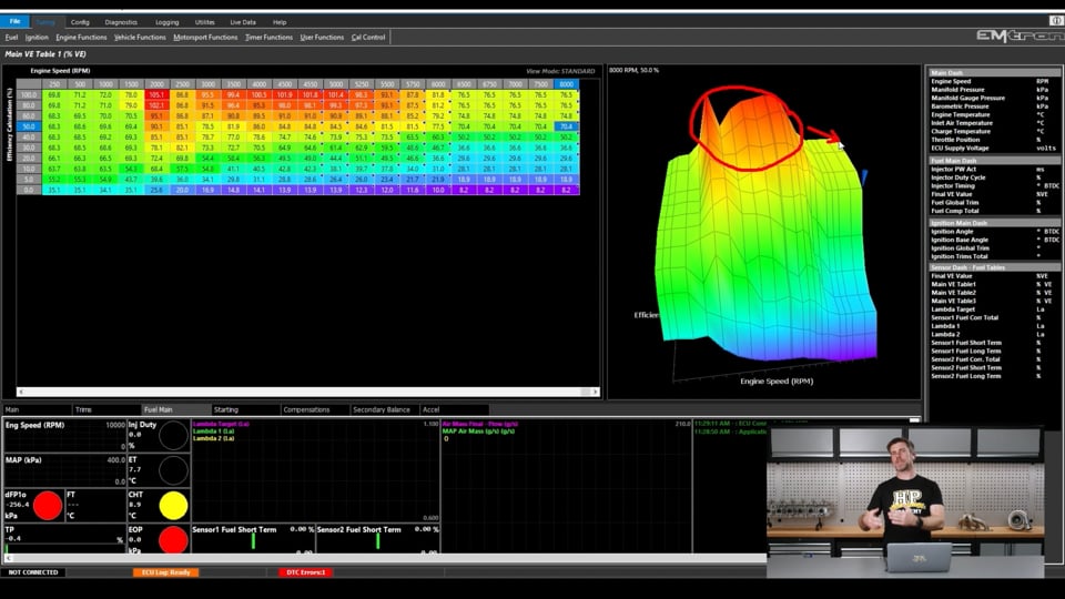
| 13:53 | So what we're actually doing is using two completely separate VE tables, so we'll have a look at that, fuel table, we go main VE 1 and 2, you can see there are 3, that third one is not actually being used, it's not relevant to our example here. |
| 14:09 | So we'll go to table two and this is really, this replicates as well the earlier B series Honda VTEC system. |
| 14:18 | If we look at our table 1 and we can see that it's actually only mapped out to 8000 RPM. |
| 14:24 | Given that this engine runs to 8800, it's not the end of the world but you know we'd normally want to map it beyond that. |
| 14:32 | We can also see, if we look at the shape of the VE table, we've got our peak volumetric efficiency down at low RPM, by the time we get to the end of that table out over here, the VE has dropped away. |
| 14:42 | This just indicates the cams really aren't working well, there's no airflow through the engine at higher RPM, that's why the volumetric efficiency has dropped. |
| 14:51 | We go to our high cam table which is VE table 2 and we can see now, that table is mapped out to 9500 RPM, little bit beyond where we want to go or need to go and we can see we're getting peak volumetric efficiency out here at around about 7500 RPM. |
| 15:09 | So completely different shape to the VE table. |
| 15:11 | Just like our VE table 1 for our low cam. |
| 15:14 | This time we can see, if we look at the VE table two, our high cam fuel table, VE table, it's very low, the volumetric efficiency is very low down at low RPM, down in the 3500, 4000 RPM area, specifically way lower than we were on our low cam table. |
| 15:33 | Alright so that's the setup but there's obviously a bit more to it than this and we need to figure out how that all works. |
| 15:40 | So we're going to go through this and basically talk about our workflow. |
| 15:44 | So what we'll do, if we're starting from scratch, we would start by actually configuring our switched cam setup and we do that by going to our functions which is already there in front of us but I'll just show you anyway. |
| 15:57 | Go to our functions and then output setup. |
| 16:01 | So this allows us to basically configure what functions we want to use and of course the one that's relevant to us here is cam switch. |
| 16:10 | So it's already turned on, obviously if it wasn't, we'd need to turn it on. |
| 16:14 | In this particular instance as well we also have our VVT cam control so that's variable valve timing, this is the continuously variable element which we're not really touching on today, you can see that that also is enabled and set to Honda K20 VVT. |
| 16:28 | So one we've done that, that actually activates or allows that particular system or strategy to become available. |
| 16:37 | Now we can come back over to our tuning workbook here. |
| 16:41 | And what we want to come through to is our engine functions, click on that and we can see, a lot of these are greyed out, these are the ones that haven't been activated but the one we obviously want here is our cam switch and we'll start with our cam switch setup. |
| 16:58 | So there's a bunch of lockouts that we can employ here and really this is up to personal preference. |
| 17:05 | So for example, this isn't actually something I've tuned, this is still as delivered but we see here we've got an RPM lockout. |
| 17:11 | So irrespective of what we've got it programmed into our cam table, the high cam profile cannot be activated below 4000 RPM. |
| 17:20 | I've never seen it myself but there is sort of urban legend that if you enable the VTEC mechanism too low in the RPM, because it is oil driven, it can cause problems with essentially not enough oil getting to bearings and other parts of the engine that require it. |
| 17:38 | So 3500 or 4000 RPM would be probably about as low as we'd want to go. |
| 17:42 | We're only really going to be doing that when we're testing to optimise the VTEC changeover point anyway. |
| 17:48 | Certainly unless something was very wrong, you're never going to want to switch to high cam at such a low RPM. |
| 17:56 | Likewise we've got the ability to have an engine temperature lockout so 35° there. |
| 18:03 | The reason that that's important is that this system is oil driven. |
| 18:12 | So there's a relationship between our oil temperature and our engine temperature and also obviously at lower engine temperatures we don't necessarily want to be driving the engine very hard so we can sort of incentivise that by making it not switch over, hence there's no power at high RPM. |
| 18:28 | We also have a TPS lockout, you can incorporate that if you want. |
| 18:34 | That would be another way of essentially getting this windowed control without what we're going to look at. |
| 18:41 | Oil pressure lockout, again obviously it's oil pressure controlled. |
| 18:44 | There is an oil pressure switch on some engines as well, we can use that. |
| 18:48 | We could use a speed channel, speed lockout if we have got that channel active. |
| 18:53 | And you could also incorporate a user lockout so a lot of flexibility here. |
| 18:57 | No real right or wrong way of setting this up, it's really just dependent on what you want to achieve here. |
| 19:03 | One thing I will mention here that does probably warrant a little bit of care is the switch on to switch off hold timer. |
| 19:11 | This can be used to, in a way introduce a little bit of hysteresis into the system where it's not going to switch on and off rapidly if you happen to be holding it at the RPM switchover point. |
| 19:25 | Do want to be very careful with that though, if you've got a very long hold time there of more than a few 10ths of a second, this could have some unintended consequences on your drivability and the control strategy so just again, a little bit of caution is needed there. |
| 19:39 | So that's our main setup there. |
| 19:42 | Then we also have our actual cam switch table and we'll come to that. |
| 19:46 | So we've got that flexibility to set this up really however we want. |
| 19:52 | This, as you can see, is set to a 3D table with our engine RPM on the horizontal axis and our throttle position on the vertical axis. |
| 20:01 | If you just want to use RPM, absolutely no problem, you could set this up as a 2D table, remove throttle position from that load axis. |
| 20:09 | The other thing that's worthy of mentioning here is this particular engine runs individual throttle bodies so that is why throttle position is being used as the load axis to match the VE table and the ignition table. |
| 20:22 | In a conventional engine with a plenum and single throttle body, we'd most likely be using manifold absolute pressure for that axis. |
| 20:29 | Just as a point here, you can either use the A key or right click and go to axis setup and that's going to let you enable or disable the axes, so obviously we've got the X axis here set to engine speed. |
| 20:42 | We also already had a bit of a look as to how we can manipulate these numbers. |
| 20:48 | You can enter them directly which you saw me do just before. |
| 20:52 | Alternatively if you're starting from scratch, rather than entering every break point, you can just use the axis setup tool here. |
| 21:00 | You can enter a starting value, an increment and a number of sites and then just click generate and that will make that for you. |
| 21:07 | Y axis here, so we've got throttle position, again you can click select and you could enter manifold pressure if you wanted, we've got that sitting here, I won't change it though. |
| 21:17 | Or alternatively if you unclick the tick box, that will of course make that Y axis disappear. |
| 21:23 | Alright so it's not too dramatic but what we can see is sort of our changeover point here at wide open throttle down to about 40% throttle, 50, we're changing over at 5 to 50 and then at higher RPM, 6000 RPM. |
| 21:39 | So kind of shows that trend, maybe not quite as dramatic but it shows that trend that I was talking about. |
| 21:46 | Alright so that's going to be changing our cam position but then we need to figure out how we're going to use our VE and our ignition tables. |
| 21:57 | So at this point we could still use this on a single table, all of those problems that I mentioned but as we've already talked about, we do have two VE tables and if we go to our ignition we've got the same, two ignition tables as well. |
| 22:13 | Alright so how exactly do we deal with that? So if we come down to our fuel table control, and we go to our main VE table. |
| 22:22 | So this is where we can select the tables that we're going to be using. |
| 22:26 | So for example we can choose table 1, table 2 or table 3. |
| 22:31 | In this case, the selection that has been used is number 6 which is on using the Z axis to control switching between the two tables. |
| 22:44 | So we've got two tables and we're switching between them using the Z axis. |
| 22:47 | Well we could use more tables if we wanted but in this case, absolutely no need. |
| 22:52 | If we just quickly go over to our ignition table, it's exactly the same here, ignition main tables, same on with our Z axis control. |
| 23:00 | OK so that's now going to allow us to switch between our two tables using our z axis. |
| 23:06 | Let's figure out how we can define that Z axis. |
| 23:09 | We'll come back across to our fuel, fuel and ignition are the same so we're not going to double up here. |
| 23:14 | And what we want to do is come down to our Z axis setup and click on fuel main table Z axis setup. |
| 23:21 | Alright so pretty straightforward here, we've got a simple 2D table, it's only got 2 break points. |
| 23:27 | The axis as we can see is cam switch status and that is either 0 or 1, it's on or it's off. |
| 23:34 | And then we're defining which of the two VE tables we're in, either VE table 1 or 2, based on that cam switch position. |
| 23:43 | Now of course if you're coming into this, you can use this Z axis for just about antyhing you want. |
| 23:50 | So chances are it's probably by default not going to have cam switch status as the break point, sorry as the axis there but again if we press the A key, you can use that select button and basically go through and find anything that you want to set that axis up to. |
| 24:06 | So that's now going to switch us between our two VE tables and our two ignition tables based on the status of our cam switch, whether we are on our high lobe or our low lobe cam position so it's reasonably straightforward but what it does do is it creates a little bit more work with our tuning in terms of what we're going to do with optimising the VE table. |
| 24:34 | We'll go through that tuning process but before I do that, this is a good time to ask any questions that you may have. |
| 24:43 | I'll get into those in a moment so anything relevant to today's topic, please feel free to ask those in the chat. |
| 24:50 | So essentially what we want to do is set up our two tables to start with. |
| 24:55 | And this doesn't have to be set in stone right from the get go. |
| 24:59 | It's very easy to manipulate these, add or remove break points and do whatever we need as we go and we find basically we start dialling in our tune. |
| 25:10 | Now probably if we're dealing with one of these engines that we're familiar with, you're going to probably have a reasonably good idea of what sort of RPM we're going to be switching over at. |
| 25:22 | For example here, I know that we're probably going to be somewhere between 4500 and 5500 RPM under wide open throttle. |
| 25:29 | The Nissan VVL on the other hand switches quite a lot higher and is also quite cam dependent. |
| 25:37 | So what we've got is we're going to start by setting up our break points and again, there's no need to go all the way out to 9500 RPM on our low cam VE table. |
| 25:49 | We're not going to be operating there and there's no point spending needless time. |
| 25:56 | But what we can do is essentially start by having our cam, our switched cam set to only be on the low cam, just basically disable that table, set the switched cam table to 0 everywhere so that we are only operating on our low cam. |
| 26:12 | And I'd probably start by sort of filling this table out reasonably thoroughly out to maybe 5500 RPM or thereabouts, right the way through. |
| 26:21 | No point again getting too fussy when we don't know exactly where the switchover point's going to be. |
| 26:25 | Then our second table here, our VE table two, we can basically extrapolate, copy and paste the numbers from the RPM sites we're already at and then extrapolate those numbers out. |
| 26:37 | Now again as I mentioned, don't really want to be switching your high cam on at idle or very low RPM so there's a bit of a process to this. |
| 26:46 | What I generally will do here is perform some wide open throttle ramp runs and I'll start by switching the high cam off to maybe 6500 or 7000 RPM. |
| 26:57 | We don't need to go out past that point, basically I'll run the engine on the dyno, right up to the point where the cam switches in and then abort the run. |
| 27:06 | So we've got that data through there and then I'll switch the cam on at lower RPM perhaps 4000 RPM and we're going to get a point where those two graphs cross so that's essentially our ultimate or optimal VTEC changeover point and then we can put that into our table. |
| 27:22 | WHat we'll find is usually there's also the need to sort of do a bit of testing, maybe move it higher and lower by 100 RPM once we actually have the cam switching to get the best result. |
| 27:34 | But that will give us that, then we know at least at wide open throttle, what our ultimate cam switchover point will be. |
| 27:41 | Now you might be sort of thinking, right well that's fine, how do we go about finding these other points. |
| 27:47 | So we'll go to our cam switching table and we can see here 30% throttle, probably going to be able to do most of a ramp run on the dyno at 30 or 40% throttle. |
| 28:00 | Not going to be too pretty but you can do exactly that same process at those lower throttle settings. |
| 28:07 | Just do a ramp run on just the low cam and a ramp run with the high cam switching in early and you'll find that changeover point. |
| 28:15 | Then what we can also do down in the lower load, higher RPM areas is we can hold the engine in steady state, look at the torque figure with everything optimised in terms of fuel and ignition, manually then change the cam switching table to switch into the high cam mode and look at whether we gained or lost torque. |
| 28:36 | So that's really if you want to get granular on it but generally what you'll find is that there's going to be a reasonable trend in the table that you can sort of follow and again if you're doing this, you're already probably ahead of 95% of tuners out there who won't bother and will just use RPM. |
| 28:53 | So if you're maybe switching at 6500 RPM instead of 6600 RPM, you're probably there or there abouts anyway and you're starting to really split hairs. |
| 29:05 | So once you've got all of that dialled in, the key here is having a little bit of flexibility on each side of those changeover points. |
| 29:14 | So what were we, sort of somewhere through about this area here. |
| 29:19 | Think it was something like that. |
| 29:20 | I would definitely want my VE tables, both the low cam, I'd be wanting to fill out, do a pretty good job of filling out this area here, and on my high cam, obviously we're not going to change here but on my high cam, I'd do the same, I'd want to fill out a little bit of the area below that optimal changeover point and what this means is that if we've got a bit of hysteresis with our changeover, or that delay in the switchover point, we know that irrespective, if we're on the wrong cam position at a certain RPM, we've still got the correct VE table, our fuelling will still be accurate. |
| 29:57 | Now I will also mention, in terms of fuelling, the air/fuel ratio will generally have a little bit of a wobble, maybe a slight lean spike or a slight rich spike across that changeover point and that's not necessarily something to really worry about or beat yourself up on too much. |
| 30:18 | A little bit of variation across that changeover point is pretty typical, you're probably, depending on the way that you're actually getting air/fuel ratio data into the ECU, you're probably not going to see a nice perfectly smooth curve across that but as long as the engine is nice and crisp across that changeover point, it's not really an issue. |
| 30:38 | Now the other advantage of using this style is coming back to some of those delays in terms of the engine coolant temperature etc, what that means is that provided you do a reasonably good job on that low cam profile VE table, maybe go out a little bit further than I just suggested, you're going to be able to deactivate the high RPM switchover point and still have a VE table that works. |
| 31:04 | If you were doing that with a single VE table and for one of those lock outs for whatever reason was not allowing the VTEC switchover to work, once you're past the VTEC switchover point, what you're going to have is fuelling and ignition timing suited to a cam profile you're not running on. |
| 31:21 | Typically what you're going to end up seeing is the engine's going to run excessively rich so again not to say that's the only way of doing it or it's essential but it is a very thorough way of getting the best results. |
| 31:32 | Albeit at the expense of a little bit more work from the tuner. |
| 31:37 | Right we'll jump into our questions now, if you've got more, please remember to put those in the comments. |
| 31:52 | Question from Manitou Black who's asked, does variable cam advance often affect the VTEC activation point and can it be used to smooth the transition? Yeah the cam position will also affect the VTEC changeover point so there's a bit of iterative process here of changing your cam control target and then going back and readdressing your VTEC changeover point. |
| 32:19 | The reality is that for the most part you're going to find that there isn't a massive change in your cam position across the VTEC changeover point. |
| 32:28 | So cam position, I'm talking about cam timing with the continuously variable cam control element. |
| 32:34 | But it is as I say an iterative process of testing and refining both of those together. |
| 32:41 | I wouldn't say smoother transitions, so if you have the transition point optimised it should actually be very smooth, you shouldn't see big steps in the volumetric efficiency, you shouldn't really feel it, you'll definitely hear it but one of the aspects with tuning a K20, if you take it from a factory calibration and then you optimise the VTEC changeover point, from what I understand, the factory engineers actually use the VTEC changeover point in the stock calibration to help with their emissions so it's not optimised for power and torque and for this reason it's actually quite a noticeable step in terms of power and torque when the VTEC changeover point occurs. |
| 33:24 | When you actually optimise that in the aftermarket tuning world, you're going to find that a lot of that step actually is removed, it's not as noticeable to the driver, the car will be more powerful through the mid range making more torque but the actual step change is reduced so that's something to keep in mind, if you have got a big step it's possible that your changeover point is not optimised. |
| 33:49 | Gizzmotorsports has asked, for street tuning the crossover do you use some sort of dyno maths or virtual dyno? Can you recommend a program to input numbers or a method for ramp run street tuning? Unfortunately this is one of those sensitive areas where I really do feel that doing this on the street is going to be a guess at best. |
| 34:11 | I'm not a massive fan of virtual dyno, I know there are a lot of people using the virtual dyno software. |
| 34:18 | The reason I'm not a massive fan is there is a lot of variability that comes into this. |
| 34:23 | However if you have no option it is probably better than a pure guess. |
| 34:29 | The process would be exactly what we do on the dyno performing two back to back runs, one with the VTEC changeover point coming in low, one with it essentially not coming in at all or very high and then overlaying those graphs but I would imagine using virtual dyno, you're probably only going to be able to get within maybe plus or minus 250 RPM window of the actual optimal point so obviously if you haven't got access to a dyno then it kind of is what it is. |
| 34:56 | Alright team that brings us to the end of our questions. |
| 34:58 | So remember for anyone who is watching this in our archive later on if you've got further questions, please feel free to ask those in the forum and I'll be happy to answer them there. |
| 35:09 | Thanks for watching and we'll see you next time. |
Timestamps
0:00 - Introduction
0:30 - Project overview
1:37 - What is switched cam control and how does it differ from variable cam control?
4:38 - Issues caused
5:36 - Control options | Single table
8:57 - Control options | Multiple tables switching with cam position
15:33 - Workflow
24:34 - Tuning process
31:52 - Questions


