319 | Introduction to Maxx ECU PDM20
Summary
Power Distribution modules are becoming increasingly common and in this webinar we’ll take a look at the Maxx PDM20 and understand how it works, how to communicate with it and how to utilise it to power and control various functions on our car.
| 00:00 | - Hey team, Andre from High Performance Academy here, welcome to another webinar and this time we're going to be diving into the PDM that is incorporated with the MaxxECU suite of products. |
| 00:12 | So in this case we're dealing with their PDM20 and we'll dive into what that is, what you might want one and what it does, we'll look at some of the software setup and configurations and a few things that you do need to keep in mind. |
| 00:26 | Before we do that, I will mention as well that we will be having a question and answer session at the end, so if there's anything that I talk about today that you'd like me to expand on or go into a bit more detail, please feel free to ask those questions. |
| 00:38 | Hold off for a moment, we will put a shoutout for those questions a little bit further along as we go. |
| 00:44 | I will mention this is a relatively straightforward product and we will be doing a relatively basic overview of it in this particular webinar so probably a little shorter than our normal webinars. |
| 00:57 | For a start, what is a PDM? If you have been living under a rock, I'll cover that off briefly. |
| 01:04 | PDM stands for power distribution module and essentially it is a way of getting rid of conventional fuses and relays and instead of using and relays to switch high power outputs to outputs such as maybe your fuel pump, maybe your thermofans, maybe your starter motor just to name a few options, instead of using fuses and relays, what we're doing is using solid state electronics to switch those outputs. |
| 01:31 | There are a few key advantages to using solid state electronics in comparison to fuses and relays. |
| 01:38 | One of these is that it dramatically simplifies your wiring installation and this is one of the things that I think is really important to focus on or keep in mind when you're considering a power distribution module for any installation, regardless whether it's Maxx or a competing brand. |
| 01:56 | Obviously there's a cost that goes along with choosing a power distribution module and it's not insignificant and people quite often will just look at that outright cost and then decide that it's just not worth it. |
| 02:09 | The reality is, before you make your decision, you actually need to be weighing up the total installed price. |
| 02:16 | Now of course if you're doing this yourself then it's more time than money, yes there's a cost involved in fuses, relays and switches but generally that's relatively low. |
| 02:26 | If on the other hand you are paying a professional to do your wiring install then it is a very time consuming task to wire up individual fuses and relays for the different circuits you need to supply power to and by getting rid of those and using a power distribution module, this cuts a significant amount of time out of the installation, which obviously time is money. |
| 02:49 | So really important just to not overlook the time saving that a power distribution module gives, I would say for all intents and purposes, using a power distribution module, even factoring in the time saving, it is still going to be in most cases, a more expensive option but that cuts down the difference in cost dramatically and then you might start factoring in the advantages in using the PDM outweigh the extra cost. |
| 03:16 | Obviously, that's a personal decision there. |
| 03:18 | Before we go on, probably should have started this with a bit of a view of everything so let's jump across to my laptop screen here. |
| 03:25 | So the vehicle that we are using is one of our in house test cars, this is a Honda City fitted with a B18C Type R naturally aspirated engine and we are using the MaxxECU Race, so that's the ECU on the right hand side here, and to the left of it we've got the PDM20. |
| 03:44 | So nice small footprint, it's actually a really, this sounds like an irrelevant aspect but it's actually quite a chunky, heavy unit. |
| 03:53 | That, again might sound irrelevant but one of the aspects of this is a lot of heat is dissipated from these units and by making it a little bit heavier like this, this actually acts as a bit of a heat sink and can be beneficial in terms of getting rid of, dissipating that heat that is produced. |
| 04:11 | Like most power distribution modules, we've got a centre stud here which is the 12V supply. |
| 04:16 | This actually comes from, you can just see it just at the top of the shot, we're using a MSEL, Motorsport Electronics electronic killswitch here as well. |
| 04:27 | So at the bottom, we can't quite see it, we've got the two connectors here, this uses the pretty popular Superseal 1.0 connector so pretty easy to source components, connectors, back shells, terminals etc for it. |
| 04:43 | Alright I'll head back across to my notes, now that we understand what we're actually talking about. |
| 04:49 | I will just dive into those benefits that I've kind of alluded to. |
| 04:52 | So using solid state electronics, obviously as I mentioned, we get rid of our fuses and relays, this is all done electronically so the advantages here is that unlike a conventional fuse, we can set up an output to retry multiple times so if something's just starting to trip, maybe you've got an output that's on its last lets and it's drawing a little more current than it typically would and if that was a conventional fuse, it'd blow the fuse and then game over, we need to physically replace that fuse in order to get that output back up online and working. |
| 05:25 | With a power distribution module, because it's electronically controlled, we can set it to trip at a certain current and then retry a number of times. |
| 05:34 | We also get real time information about the current draw on each of the circuits. |
| 05:39 | By logging this as well and monitoring it, it can give you a sense of if something is maybe starting to fail, if you see some historic data and the current draw is starting to increase on maybe a fuel pump, then this could be an indication that there's a problem with your system so quite beneficial in that element as well. |
| 05:57 | Right the elements that I'll talk about here as well is how we configure the power distribution module, the MaxxECU power distribution module, this is all done through the MTune software, so the same software we use for configuring the ECU. |
| 06:11 | So this is quite handy because it's all in one place. |
| 06:16 | Potential downsides is that this is really a product that is only made to work with the MaxxECU so installing it with another brand of ECU is going to be difficult or maybe even impossible. |
| 06:31 | Interesting choice that Maxx have made in this regard. |
| 06:34 | Most of the PDMs that I come across, probably the newer Haltech option would be the other one, everything else really is almost univiersal because it communicates via CAN so you can choose to use maybe an Ecumaster PMU16 like we have with a MoTeC M1 ECU or a Link ECU or just about anything else, you could include it with the MaxxECU. |
| 07:02 | So that's not how Maxx have done this, their PDM's really designed solely to work with the MaxxECU. |
| 07:09 | Alright so let's jump into our software, and I'm actually offline with the car at the moment but if we just turn it on for a moment and I'll try not to flatten the battery. |
| 07:19 | So one of the elements we can see here is up the top we've got this status bar that's gone green at the moment and what it's saying to us is that the ECU and the PDM are both online. |
| 07:30 | I'm just going to switch this off now for the moment so that we don't end up flattening the battery. |
| 07:36 | We've got our ECU tuning tree on the left hand side and again obviously we're going to be focusing primarily on the PDM for this. |
| 07:46 | Which we can see is down here. |
| 07:49 | If you are interested in learning more about the MaxxECU in general, we've got an introduction webinar to the MaxxECU that you will find in our webinar archive so check that there. |
| 08:00 | Alright so let's just expand out our PDM and for a start, and I'm not going to deal with everything here but for a start we've got our PDM version which will just show us the version of firmware that we're running and you can do a manual update of the firmware if you want to. |
| 08:17 | Usually always a good idea to make sure that you are staying current with firmware. |
| 08:22 | There's always bugs that are found over time or new functionality that is added to products, both ECUs and power distribution modules and generally I'd always advise staying up to date with the latest to make sure that you're on top of that. |
| 08:36 | Only thing to be a little aware of, and this really is just an across the board guide or rule of thumb is updating the day before a race meeting, not usually something I'd recommend, just in case you find some odd new bug that's been introduced, sometimes the devil you know is better than the devil you don't so take that with a grain of salt, it's up to you how you do that but that's generally the rules I live by. |
| 09:03 | Let's move down to our PDM settings. |
| 09:06 | Now the one that I really want to deal with here because this can trip you up, if you don't read the instructions, which obviously we always read the instructions, but most people don't, is force one output to ECU supply and you can see that that is enabled. |
| 09:24 | So why do we have this and why is it enabled by default? Well the problem with this is if we are incorporating the PDM into our ECU installation, of course we are going to power the ECU via one of the outputs from the PDM. |
| 09:39 | That gets us to an awkward situation because if we haven't configured the PDM and it's not providing output to the ECU well how do we set that up when we're using the ECU as our interface for our laptop tuning software? So the key there is that by default the output number one is always configured to be on and that is configured as an ECU power supply. |
| 10:03 | So if you follow the wiring instructions and you use that output 1 to supply power to the ECU, essentially what it means is as soon as you power up the PDM, the ECU will also be powered up, we can then communicate with both and we can go about our configuration. |
| 10:18 | Of course once you've done that, you can choose to disable this or set it however you want but just understand that that is by default how that will work. |
| 10:29 | I won't cover anything else here other than the CAN bit rate, obviously we want to make sure that that matches anything else that is on our CAN bus, and this is quite a capable unit in terms of communicating, receiving and transmitting messages via CAN. |
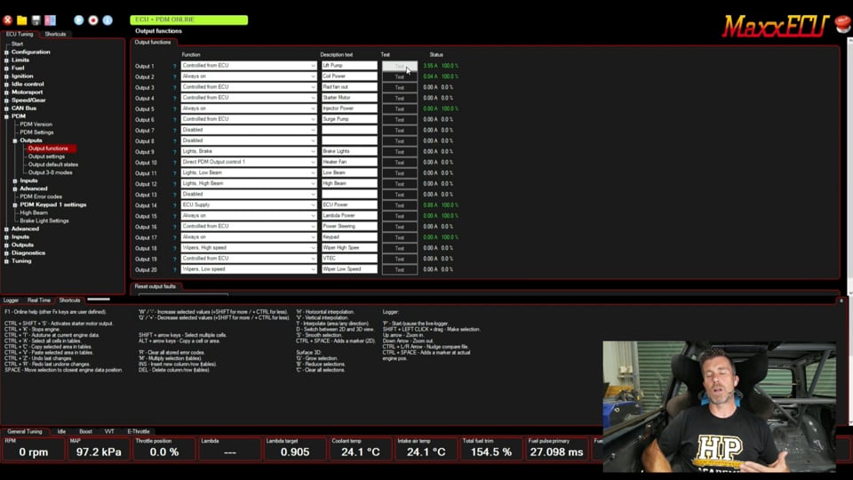
| 10:45 | OK so let's move into our output functions and we can see that in our tree here, so we'll expand that out and we start with our output functions itself. |
| 10:57 | So this is the outputs that the PDM has, as you can see they're labelled 1 through to 20. |
| 11:02 | And what we can do is have a function, so output 1, you can see that this is controlled from the ECU and we can then give it a description. |
| 11:14 | So in this case this is our lift pump. |
| 11:17 | So the ECU is actually sending the request to the PDM to actually turn that pump on and off. |
| 11:23 | Just power everything up and we'll let it go through its power cycle. |
| 11:28 | So nice function here, just like any PDM really, is over on the right hand side we can see a real time view of the current draw and the percentage of load and when we want to go through and test functions, I'll just click this test button, that will run the lift pump, we can see it's pulling about 3.5 amps and 100% load as it sits so really nice way of being able to actually test our functions and make sure they're all working, as well as actually getting a real time look at what the current draw on a particular item is. |
| 12:03 | So I'm not going to go again through all of these but for example, we've got output 2 here, that is set to always on and that is our coil power. |
| 12:12 | We've also got always on, our injector power as well and then we've got other elements such as starter motor which is controlled from the ECU. |
| 12:22 | If we look at our drop down menu, we've got a lot of control options here in terms of how a particular output is going to be controlled. |
| 12:30 | Always on, disabled, you've got the direct control, control from the ECU etc, obviously just dependent on exactly how we are setting this up. |
| 12:41 | So this is where I think maybe the control, the setup of the power distribution module is maybe a little bit less intuitive than perhaps it could be because we sort of end up setting up our outputs in two separate places. |
| 12:59 | So this is our output functions from our PDM but particularly when we've got these elements like our lift pump which is our example we've looked at, that are controlled from the ECU, how does that all work? So what we want to do here is we'll just close down our PDM for a moment and we'll come down to just our normal ECU outputs which we'll find here and if we click on our output configuration and we go back to the top, so first of all we start here with our general purpose output functions, these are ones that are wired up to the ECU header plug. |
| 13:30 | So pretty typical stuff here. |
| 13:32 | If we weren't using a power distribution module, maybe we would have these used for our lift pump for example and then it would obviously go through the relay. |
| 13:42 | Reason why we can't directly power something like a lift pump, and I should have mentioned this before, is that our ECU outputs, the transistors on the board, are not made for high current draw so I don't actually have the spec or limit for the MaxxECU, sometimes these might be 100 mA or 200 mA or less so they're really only designed for switching a relay and the relay is designed for controlling that high current draw as the lift pump might require 5 to 10 A depending on the pump itself so that's why that exists and the power distribution module is designed to basically do that directly via the solid state electronics. |
| 14:23 | So those are our onboard general purpose outputs, likewise we've got our injector functions. |
| 14:27 | This particular ECU has 8 injectors, we've got 4 for injector control and then we could again use the unused injector outputs for auxiliary output functions. |
| 14:38 | Same with our ignition. |
| 14:40 | So these are all the ECU though at this point. |
| 14:42 | Then we get down to our PDM1 and this is where we can set our functions here. |
| 14:48 | So for example, PDM output 1 function, you can see that we have set this to our fuel pump relay. |
| 14:55 | And then we go back to our PDM, we'll just deal with this one output at the moment. |
| 15:01 | So PDM output 1, we already know that we've controlled that, we've set that up to be our fuel pump relay and we can see that we've now selected that to be controlled from the ECU and it's a lift pump. |
| 15:12 | So it's sort of a bit of a weird interface there. |
| 15:15 | I don't design ECUs so I'm not sure if this is maybe the cleanest way of doing it or there's a reason why Maxx have done this but it does require going backwards and forwards between those two sections, we'll come back to our output configuration here. |
| 15:31 | So what we've got configured, we've got our fuel pump relay, our radiator fan, we've got our starter motor, fuel pump relay, we've got two of those because we've got a lift pump and a main pump. |
| 15:43 | We've got power steer and VTEC. |
| 15:46 | When you set these functions up as well, it gives you the control strategies for those functions, so for example here, radiator fan control, for example in the PDM, that is controlled from ECU, let's just check that and confirm, go back to our output functions. |
| 16:04 | Where is our fan? Looking at heater fan, radiator output there, yep controlled from ECU. |
| 16:14 | Just can't see it for looking so just basically proving what I was saying, but we can come to our radiator fan control here and this is where we control how that's going to work in terms of the turn on temperature, in this case 88°, we've got a hysteresis of 2°, meaning the temperature needs to drop back to 86 before the fan will turn off. |
| 16:32 | It's disabled above 100 km/h etc so that's where our control functionality for that comes in. |
| 16:38 | Likewise I've come back to our output configuration, PDM function 19 in this case, we've used this for our VTEC control. |
| 16:47 | Pretty basic output for a PDM, very low current draw but that's what we've got here. |
| 16:54 | So again now we've got our user output 1 is VTEC and if we come down to that, we've got our setup for our VTEC. |
| 17:05 | I'm not going to dwell on it too much but basically we've got the ability to have conditions that it will turn on. |
| 17:10 | I've kept this really simple, it is only using condition A which is just RPM, we aren't incorporating load and you can see there it's going to switch on at 3500 RPM and it's got a 50 RPM hysteresis. |
| 17:22 | So this is the interaction between essentially the ECU tuning and the PDM tuning, there's a bit of backwards and forwards that goes on in here. |
| 17:31 | Let's come back out to our PDM though, I'll close down our outputs just to keep things nice and simple. |
| 17:37 | I'll come across to our output settings. |
| 17:39 | So this is where we can control how the outputs are going to work. |
| 17:43 | So for example we've got first of all the maximum current setting for each of the outputs. |
| 17:49 | In this case output 1, 15 A which is complete overkill for that particular fuel pump. |
| 17:55 | Drove out 3.5 A before, probably want to actually set that down somewhere around about 6 A or something like that. |
| 18:03 | Then the overcurrent reset, so how is it going to actually function? What's it going to do when it gets to an overcurrent state? So you can see at the moment that's set to three retries with a 1 second delay so I'll open that up and basically you can set this up to however you prefer. |
| 18:22 | Three retries, probably maybe not quite enough, it's not going to get you too far if it's tripping quite regularly, 10 retries with 3 seconds. |
| 18:32 | The delay, it's a bit of a balancing act, obviously with a fuel pump you don't want to turn it off for too long because the downside of turning it off is that you're going to end up losing fuel pressure, turning it off though does have the effect of cooling the product, the output, whatever you're trying to run, and allows everything to sort of settle down before you turn it back on, otherwise it could go straight into an over current situation again. |
| 18:55 | You can also have an undercurrent fault, you can see we've got that switched off. |
| 19:01 | And the other nice function here is it does give the ability to run a soft start. |
| 19:05 | So with an inductive load like maybe a fuel pump or a radiator fan, if you actualy look at what happens in a log of the current draw, when that device is first switched on and it starts obviously stationary, the initial current draw or in rush current as it's referred to, is normally quite significant so we've got a fan that maybe steady state is pulling 10 A, it wouldn't be unusual to see it pull 20 or 30 A for maybe 50 to 100 ms at startup and then it'll drop away as the speed comes up. |
| 19:42 | So soft start allows you to basically ramp that in rather than just turning it straight on. |
| 19:47 | So if we look at the settings here, got the ability to ramp that in over 0.2 of a second through to 10 seconds. |
| 19:55 | So for a thermofan, maybe ramping it over 0.2 or 0.5 of a second will ramp that in slower, bring it up to speed a little slower, probably won't have much of an effect on its performance but will avoid that in rush current. |
| 20:08 | OK moving on, so this is all pretty standard PDM stuff, nothing that's particularly unusual there. |
| 20:16 | Not as much control perhaps as some power distribution modules give, given that for our over current and under current, we really only have the ability to select from this limited drop down list. |
| 20:30 | Most of the power distribution modules that I deal with on the day to day, you can physically type in what your preferences are. |
| 20:37 | Maybe we want the output to retry 50 or 100 times with a 1.5 second delay, you could for the most part achieve that as you want. |
| 20:47 | That's OK though, I mean it is still effective, it's just maybe a little bit more limited on its functionality but not really a big deal. |
| 20:56 | We'll come down to our output default states next and basically if there is a CAN error, you can choose what's going to happen. |
| 21:07 | So in most instances, what we want to do is keep the existing state from before the CAN error existed, given that the ECU and the power distribution module communicate to each other via CAN so what I'm getting at here is if the ECU requests and output like our thermofan to turn on and then we're really relying on that CAN messaging to turn it back off or control it. |
| 21:33 | So if there's a problem on the CAN bus or errors then you can choose what's going to happen, so keep the existing state or you can turn it off or you can turn it on. |
| 21:42 | Really, that's going to depend on what the output is and ideally in the perfect world, we don't want there to be CAN errors but sometimes that can happen. |
| 21:54 | You can also choose to force the outputs off when the key is turned off. |
| 21:59 | Again depending on really how you've got your wiring set up will be your preference there. |
| 22:07 | Next we'll come down to our output modes, 3 to 8. |
| 22:11 | So this is actually a function that I see a lot of power distribution modules don't have in that we can drive to 12V for our outputs so it lists here what we've already got these set up as from our output configuration we've already looked at and you can see that all of these currently drive to 12V so what that means is that for our radiator fan for example here, we would need to ground the other side. |
| 22:38 | Obviously it's a 2 pin plug for a fan. |
| 22:40 | This will provide the 12V when it switches on and we want to ground the other side. |
| 22:46 | But if we look at our drop down menu, we can also set up an H bridge, half bridge output for this as well. |
| 22:53 | So that's useful for speed control for example, you've also got a 12V driving with a wiper park grounding. |
| 23:02 | So this is really a very specific function for windscreen wiper control. |
| 23:06 | Those need to be dealt with carefully and they will have a park switch so that if you wire it up correctly and you configure it correctly in your power distribution module then the wipers, when you turn them off will continue a sweep and come back to that park position before they actually stop moving, just like they do in your factory car. |
| 23:27 | Alright let's close down our outputs now and we'll move down and have a look at our inputs. |
| 23:34 | Nothing particularly special here, you can wire inputs directly to the PDM20 as opposed to brining them in from the ECU. |
| 23:44 | We've got 3 set up here, let's have a look at our input 1 which is set up as our master killswitch to our MSEL killswitch. |
| 23:52 | So we can see we can give it a description here. |
| 23:57 | Nothing particularly unusual there. |
| 23:59 | We can set this up as a digital or analog input. |
| 24:01 | So a switched input like our killswitch, obviously that's either on or off but alternatively maybe you want to wire up a fuel pressure sensor into the PDM direct, I'm not quite sure why you would want to do that but you could. |
| 24:15 | So digital input there, we've got pull up resistor in this case disabled and then we've got the functionality here which is a main power safety shut down. |
| 24:25 | So when our MSEL killswitch is off, this will basically shut down the power to the power distribution module and hence everything else in the car. |
| 24:36 | So we've got our brake switch as well, pretty much exactly what you'd expect here, and we've also got a clutch switch so nothing particularly unusual, if you've ever set up a digital or analog input on an ECU, it's essentially exactly the same. |
| 24:51 | We'll come down to our advanced settings here and not really going to go into too much detail because we aren't using these in this particular example. |
| 25:00 | If there's demand, we may go a little further into this but essentially one of the nice features with the MaxxECU is it is a very powerful device in terms of its CAN functionality. |
| 25:10 | So you can bring in inputs over CAN, you can also output channels via CAN so that they can be read by other devices, maybe a dash for example, to be logged. |
| 25:23 | Again I'll close that down because we're not using any of that functionality. |
| 25:29 | Now I'll deal with the keypad settings and we're going to move into our Q&A fairly shortly after that so this is probably a good time, if you've got any questions on what I've been talking about, or maybe anything you think I've missed, please ask those in the questions and I'll get into those in a second. |
| 25:49 | Now the keypad settings is one of the areas where you do need to be a little bit careful because we've got our PDM keypad 1 settings here, which I'll just expand out. |
| 26:01 | And we've also, if we come up further into CAN bus here, we've got keypad 1 settings here as well. |
| 26:11 | So the problem is we've got the keypad which is a Blink Marine 8 button keypad, we've got this on the same CAN bus that's communicating to the ECU as well as the PDM so you just need to be careful how you configure this in terms of what a particular function is talking to, whether it's to the PDM or whether it's to the ECU. |
| 26:33 | So for example, if we come down to, we're at the moment in the ECU, come down to button 5 which is our pit limiter, clearly a function that we're going to be actioning through the ECU. |
| 26:46 | We'll click on that and we've got our settings for that, so it is a pit limiter, it has two positions and the function for this is our speed limit 1 enable or set. |
| 26:58 | That then allows us to go into our speed limit 1 and actually set up what we want that to be when our pit limiter is active. |
| 27:04 | You've also got the ability here to change the colours of the buttons depending on the status of that output. |
| 27:11 | So that's going directly into the ECU. |
| 27:13 | What we don't want to be doing is then trying to reutilise that inside of the PDM so if we come down to pit limit 5 inside of the PDM settings this time, we can see that this is not used or used by other ECU or PDM so just important to stay on top of what's going into the PDM and what is going to be going into the ECU. |
| 27:36 | On the other hand, if we look at our start/stop button, nope not that one, flash to pass, start/stop button is also actually going through an ECU function and you'll remember that the starter motor, the output for that is controlled from ECU so that's why that button doesn't actually go into the PDM essentially. |
| 27:55 | So yeah if we look at the functionality here, so flash to pass, it's a momentary button and the function for that is lights flash to pass, and then we can control our functionality here as well as our lights or basically do anything we want. |
| 28:12 | So a lot of flexibility here to set this up, essentially however we want it to work. |
| 28:19 | But again just making sure that we are separating our functions of what we want that keypad to do between the PDM and the ECU. |
| 28:29 | The main settings for our CAN keypad are actually here in the ECU so we can see that is a Blink Marine 8 button keypad and we've got the ability to choose whatever we've actually got connected there. |
| 28:44 | Again this sort of comes back to simplifying our wiring as well. |
| 28:48 | Unfortunately it's out of shot so I can't show it but most people have probably at this stage seen either a Blink Marine or a Grayhill CAN keypad, they're pretty common these days. |
| 28:57 | And the advantage with this is the wiring only requires 4 wires, we've got CAN high and CAN low, we've got 12V and ground and basically then we've got 8 buttons or 15 buttons or however many our keypad has that we can then utilise for functions inside of the ECU, the PDM or both. |
| 29:16 | So really really quick and easy compared to wiring up individual switches and buttons. |
| 29:22 | Right, again we'll go into those questions shortly. |
| 29:26 | One last thing I just wanted to look at here is some of the functionality in terms of the, I think we are advanced and internal outputs. |
| 29:36 | So this is, I just wanted to show you the starter motor control here or the kill function for stopping the engine. |
| 29:42 | We've got push button start and it's also beneficial to have on the same button, press it again and it will kill the engine. |
| 29:49 | So how that's done, because this function is sort of through the PDM as well with the starter motor control. |
| 29:56 | So if we go into advanced and then internal outputs. |
| 29:58 | So again just important to mention, this is in the ECU, not the PDM control. |
| 30:03 | If we look at internal output 1, our function there, we've called this stock engine. |
| 30:09 | And the condition there is that button one, which is our start/stop button, you can see that that is equal to one which is when we've pressed it, it's a momentary button. |
| 30:20 | Condition B though here, our RPM must be greater than 600 RPM. |
| 30:25 | So essentially we want to make sure that the engine is running. |
| 30:28 | So the output configuration for this, conditions A and B must be true, not just one of them. |
| 30:33 | And we've got this turn off delay of two there, so two seconds, so basically when this function actuates or activates, it will stay true or active for two seconds which should be enough to kill the engine and then the input to control is the stop engine or prevent start function so that will basically just stall the engine. |
| 30:53 | So that pretty much does it for our basic look into the PDM20, again not a lot, anything out of the usual for anyone who has already dealt with a PDM. |
| 31:06 | Couple of unusual elements in terms of the way this sort of configuration both within the ECU as well as the PDM for functions that you want to control via ECU outputs but just beyond that, it's pretty self explanatory for the most part. |
| 31:22 | However, we'll jump into our questions and see how well I have explained that so let's get into those, if you've got more questions, please ask those. |
| 31:34 | Nathan has asked, why don't we see more mainstream manufacturers using power distribution modules? Shouldn't they be cheaper to implement? Sorry a little bit off topic, looking for some triple down. |
| 31:44 | Well you're actually seeing most, or I wouldn't say most, a lot of mainstream OE manufacturers do actually incorporate essentially power distribution modules within their cars now, body control modules as they're often referred to. |
| 31:59 | Some of these were still mechanical but a lot of these now are solid state. |
| 32:03 | I mean I guess really in terms of the aftermarket world, it still comes down to, it's a cost element to produce these units. |
| 32:11 | They've come down massively in cost just in the time that I've been involved in the aftermarket industry. |
| 32:16 | When I first got started, these really were solely used in very high end motorsports and probably you were looking at price tags north of $10,000. |
| 32:27 | Now some of these are down in the $1000 to $1500 USD range so they really have come down dramatically and you've got a lot more selection so yeah I mean it's still, there's a cost there to manufacture these and for an ECU manufacturer, they've got to kind of look at the opportunity, cost of developing that product vs maybe a new ECU, hopefully that answers your question there Nathan. |
| 32:51 | Looks like we haven't got any more so we'll leave it there for this webinar. |
| 32:56 | As usual, if you have got questions that come up and you're watching this in our archive then please feel free to ask those questions in the forum and I'll be happy to answer them there. |
| 33:05 | Thanks and hopefully we can see you next time. |
Timestamps
0:00 - Introduction
0:58 - What is a PDM?
1:31 - Advantages over fuses/relays
3:18 - Physical overview
4:49 - Trip retry capability
5:57 - Only compatible with MaxxECU
7:09 - Software overview
9:03 - PDM Settings
10:45 - Outputs
23:27 - Inputs
24:51 - Advanced settings
25:28 - Keypad settings
29:26 - Internal outputs


