145 | How to Calibrate Common Sensors
Summary
One of the most important pre-start configuration tasks with any ECU is to ensure that the sensors wired to the ECU are configured correctly and reading accurately. In this webinar we’ll discuss some of the most common sensors we use and look at how to correctly calibrate them inside the ECU. In particular we’ll look at setting up fluid pressure sensors, MAP sensors, and temperature sensors.
| 00:00 | - It's Andre from the High Performance Academy. |
| 00:02 | Welcome along to today's webinar, where we're going to be having a look at how we go about calibrating the sensors, the various sensors that are input into our ECUs. |
| 00:13 | Now as usual we will be having questions and answers at the end of today's webinar so if there's anything that I discuss that you'd like me to go into more detail on, or anything relating to sensors and sensor calibration with our ECUs that you'd like me to discuss, please put that into the comments or the chat and the guys will transfer those through to me, we'll deal with those at the end. |
| 00:35 | Now we'll start by discussing the importance of calibrating the sensors into the ECU. |
| 00:41 | Basically everything that the ECU does, everything that the ECU controls is based on the input from the various sensors that are wired up to the ECU. |
| 00:52 | So essentially it's a case of if we have garbage data going into the ECU it's impossible for us to expect the ECU to be able to do its job properly and correctly control the fuel delivery, the ignition timing, and whatever other functionality that we're expecting the ECU to manage based on the input from the various sensors that are going into the ECU. |
| 01:16 | Now this is also made a lot more difficult when we have our laptop in front of us, and we're looking at a digital number for let's say engine coolant temperature on our laptop screen. |
| 01:27 | When we've got that digital number in front of us, it's often very easy to be sucked into believing that that number is absolutely accurate. |
| 01:36 | And of course if the calibration isn't correct, or the wiring for the sensor isn't correct, then we could be very much mislead by that number. |
| 01:44 | So we're going to look today at two aspects, we're going to discuss the sensors and we're going to look at how they need to be wired. |
| 01:52 | We're going to touch on that briefly because the wiring is really the first part here, the first step, in making sure that we've got reliable data from our sensors. |
| 02:00 | Then we're actually going to get stuck in and look at the sensor calibration and we'll have a look at a few examples in the Link G4 Plus, the Motec M1, and also the Syvecs ECU. |
| 02:10 | There's a few little tricks and tips that I'll show along the way that hopefully will give you some more tools to put in your tool bag that you may need later on down the track when it comes to setting up these ECUs. |
| 02:25 | OK so we'll start with discussing the two main types on sensor that we use, and these are the ones that we're going to be focusing on today. |
| 02:33 | And these are an analog voltage style output sensor. |
| 02:37 | So these are a sensor where we are outputting generally a zero to five output signal into the ECU, and that output voltage is going to be relative to whatever the signal is that that sensor's measuring. |
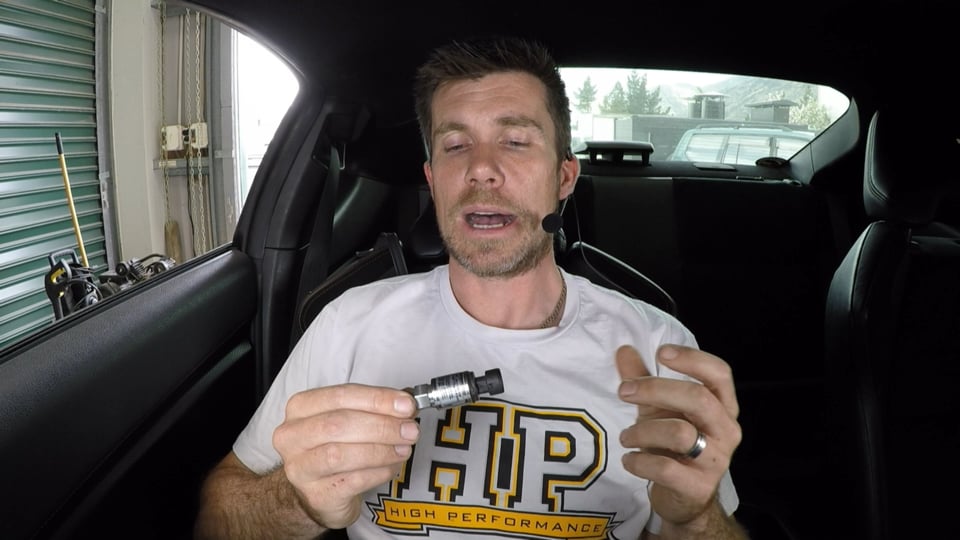
| 02:52 | So a really common example here would be a generic manifold absolute pressure sensor, I've got here a generic GM three bar sensor which is a very common sensor used for measuring manifold pressure. |
| 03:06 | So this is a zero to five volt sensor and it outputs a voltage that's relative to the pressure that the sensor is measuring. |
| 03:15 | At the same time we may also have other generic pressure sensors. |
| 03:20 | This is a AEM zero to 150 psi gauge pressure sensor. |
| 03:25 | So this is used for measuring, in this case we're actually using it for measuring exhaust manifold back pressure, obviously could be used for measuring a range of different properties where we're interested in a range that will span between zero and 150 psi. |
| 03:44 | While there are a wide range of sensors that work with a zero to five volt output, another common one that we may come across is a thermocouple amplifier which is used with thermocouples such as exhaust gas temperature sensors. |
| 03:58 | These thermocouples themselves output a very very small voltage so they're useless to the ECU directly and in order to get some useful data out of them we run the thermocouple into a thermocouple amplifier, the thermocouple amplifier then takes the input from the thermocouples, scales it, and outputs it in a zero to five volt format that the ECU can make sense of. |
| 04:23 | The other type of sensor that we're going to discuss today is one that uses a variable resistance so one of the most common sensors that we use for temperature measurement in our ECUs is a negative temperature coefficient thermistor or NTC thermistor for short. |
| 04:40 | So here I've got one of the common Bosch fluid temp sensors. |
| 04:46 | One of the ways that you can tell these sensors apart by the way is an NTC sensor will only have two terminals, as we can see hopefully in the end of our Bosch fluid temperature sensor. |
| 04:58 | Whereas if we're looking at an analog voltage output sensor such as our manifold absolute pressure sensor, we'll be able to see that they have three terminals. |
| 05:08 | We'll discuss in a little bit more detail shortly how those different sensors work. |
| 05:14 | So the NTC sensor, we're going to be using these predominantly for aspects such as air temperature measurement, we're also going to be using them for fluid temperature so this may be for our engine coolant temperature, one of the key inputs to the ECU to allow it to perform proper cold start calibration, cold start corrections I should say. |
| 05:37 | We also may be using it to measure other fluids in the car, maybe gearbox temp, maybe engine oil temperature, maybe differential temperature. |
| 05:45 | There's basically an unlimited number of applications where we can use these sensors. |
| 05:51 | Now the way the NTC temperature sensor works though is quite different, so if we can just jump across to my laptop screen, we're going to be coming back and having a look at this particular data in a little bit more detail shortly. |
| 06:03 | This is for a high speed intake air temperature sensor that measures between minus 40 degrees and 300 degrees centigrade. |
| 06:12 | The important thing to note here is the graph that we've got of the resistance of the sensor versus temperature. |
| 06:19 | And you can see that the shape of this graph is very very non linear. |
| 06:24 | And that's going to be important, we're going to find out more about that very shortly. |
| 06:28 | So the way the negative temperature coefficient sensor works, as its name implies, as the temperature that the sensor is exposed to increases, we're going to find that the resistance of the sensor decreases. |
| 06:41 | Alright I'm just going to head back across to my notes now. |
| 06:46 | OK so with the NTC sensor we know that the resistance changes but that on its own is not a huge amount of use to our ECU. |
| 06:56 | What the ECU really needs to do is measure a voltage. |
| 07:00 | And in order to do this we need to add what's referred to as a pull up resistor to the ECU wiring. |
| 07:09 | So what this does, let's just have a quick look at a pull up resistor, if we can jump across to my laptop screen again. |
| 07:15 | This is just a really basic circuit diagram of how this works. |
| 07:19 | So on the left hand side here labelled V in, this is our regulated supply voltage, this will be internal inside our ECU. |
| 07:28 | Then we have our ground point, our zero volt reference. |
| 07:33 | Then we've got two R values, two resistor values listed here we're got this R one, this is known as a pull up resistor. |
| 07:42 | So generally this is internal inside the ECU for our analog temperature inputs. |
| 07:48 | And it's a often a one kilo ohm pull up resistor that's connected on one end to five volts, and on the other end it's connected to our analog temperature input pin. |
| 07:58 | So again inside the ECU. |
| 08:00 | But we've also got here our second resistance value. |
| 08:04 | And this is the variable resistance that comes from our NTC sensor. |
| 08:09 | So this is the actual sensor itself. |
| 08:12 | So this is why we only have two pins, one pin of the sensor goes to our sensor ground, and the other pin goes to the analog temperature connection on our ECU. |
| 08:22 | And by virtue of that pull up resistor, this becomes a voltage divider, which we're going to talk about in a little bit more detail shortly. |
| 08:30 | And we end up from our variable resistance with a voltage output at that pin to the ECU. |
| 08:37 | So the way this works is that the voltage that the ECU is seeing will depend on the variable resistance. |
| 08:46 | So what we're doing is creating essentially a voltage divider by virtue of that pull up resistor inside the ECU. |
| 08:56 | OK so first of all we'll go into the wiring of the sensor and this is really one of the first places we need to start and this is often one of the areas we see a lot of mistakes being made when it comes to the installation of every aspect of the ECU but of course the sensors are no different. |
| 09:15 | It's essential to make sure that the sensors are wired correctly to the ECU so that the ECU has the best chance possible of receiving the correct signal, or the signal that we're expecting to see. |
| 09:29 | Now the thermistor signals, the NTC thermistor signals require an analog voltage input with a pull up resistor and a sensor ground so we've just talked about that. |
| 09:41 | Most often we're going to find that our aftermarket ECUs, along with our factory ECUs for that matter will have a certain number of inputs that are preconfigured to be for temperature sensors, and these will have the internal pull up resistor inside the ECU. |
| 10:01 | This makes it really easy for us from a wiring perspective because we don't need to worry about that pull up resistor aspect, we simply need to wire one side of our NTC thermistor to a sensor ground, and we need to wire the other side of the sensor to our analog temperature input on the ECU and these will generally be how those inputs are labelled as analog temperature inputs. |
| 10:26 | Another point to just note along those lines is the polarity of our wiring for an NTC thermistor style sensor isn't important. |
| 10:36 | We can wire either terminal to sensor ground and we can wire either terminal to our analog temperature input. |
| 10:44 | Now if you've got to a situation where you have used up all of the available analog temperature inputs on your ECU but you still want to add additional analog temperature sensors to the ECU so you can monitor other temperatures, often all is not lost. |
| 11:02 | We can actually add an external pull up resistor to the ECU wiring and that's relatively straightforward. |
| 11:09 | If we jump back to our diagram here for a moment, remember this is what's going on. |
| 11:14 | Our V in here is our regulated five volt supply. |
| 11:18 | Now all we're doing here is instead of having this internal with the ECU, we would wire this externally. |
| 11:24 | So we're going to have a number of five volt outputs at the ECU header. |
| 11:28 | We can take one of those five volt outputs and we can fire it through, in this case our pull up resistor. |
| 11:36 | Generally we would make this a one kilo ohm, or 1000 ohm pull up resistor and then we can wire that to our analog voltage input pin at the ECU header along with the input from our temperature sensor. |
| 11:51 | And that's essentially just going to replicate what the internal pull up resistor on the ECU is doing. |
| 11:58 | And that's going to just convert the variable resistance that that sensor is seeing or the variable resistance from the sensor I should say, and that's going to convert that into a voltage which is ECU can actually use. |
| 12:12 | OK so in terms of our analog voltage output sensors, instead now we'll move across to those, so again we're talking here about the likes of our manifold absolute pressure sensor or any of our generic pressure sensors. |
| 12:28 | We're going to need to supply these sensors with a regulated five volt supply. |
| 12:34 | And this is really important. |
| 12:36 | So remember the ECU is looking for a specific voltage input from the sensor and that voltage input is going to be related to, in the case of a MAP sensor, it's going to be related to the pressure that the MAP sensor is exposed to. |
| 12:52 | Now of course if the supply voltage to the sensor changes, then the output from that sensor is also likely to wander around and this is going to affect the accuracy of the sensor. |
| 13:03 | For this reason we find that our ECUs will have dedicated five volt sensor supply pins. |
| 13:10 | And these use an internal regulator chip inside the ECU to make sure that the voltage that is supplied to that pin is very accurately controlled to five volts and this again allows the sensors to do the job that they're designed to do. |
| 13:25 | So you'll see that the ECU often has more than one five volt sensor output, five volt sensor supply pin. |
| 13:34 | You also may find that it may also have a regulated eight volt supply pin. |
| 13:39 | It's really important to make sure that you don't use the incorrect voltage supply there for your sensor. |
| 13:45 | Almost always these sensors are going to require a regulated five volt supply but of course the data sheet for the sensor is also going to tell you what you need there. |
| 13:58 | OK as well as our regulated five volt supply, we're going to wire the sensor into an analog voltage input on the ECU. |
| 14:08 | It's important here that we are using an analog voltage input to the ECU that has no pull up resistor. |
| 14:16 | Alternatively if your ECU has the ability to electronically turn the pull up resistors on or off, this gives you more freedom, you can use any of the pins that previously were maybe configured for analog temperature, as long as the internal pull up resistor is disabled on those particular pins. |
| 14:37 | The other aspect here is to make sure, and this goes for both the analog voltage sensors as well as NTC thermistor sensors, is to make sure that they are connected, the opposite side of them is connected to a sensor ground. |
| 14:53 | Now as well with the NTC sensor I mentioned that they aren't polarity conscious. |
| 14:58 | With a pressure sensor or any sensor that has three pins, and is relying on a regulated five volt supply, these definitely need to be wired to the correct terminal. |
| 15:09 | So you'll need to check with the data sheet for the particular sensor you're using and make sure that you're supplying five volts to the correct terminal, sensor ground to the correct terminal and then you'll have the voltage output. |
| 15:21 | You wanna make sure that again you've got that in the correct place as well. |
| 15:27 | Now when it comes to the grounding, this is another area that I have seen a few really weird problems over the years. |
| 15:37 | And one of the strange ones that I have seen is where someone had wired the sensor ground from the sensor to the cylinder head or the engine block. |
| 15:48 | That's really not going to give us the result we want. |
| 15:52 | Again we're looking for very accurate voltage signals, and we want to make sure that the accuracy of those signals is maintained and that's why you're going to find that your ECU has a number for dedicated ground pins on the header plug and these will usually be labelled as something like sensor zero volt or sensor ground. |
| 16:14 | And these will be distinguished from the acutal main power grounds. |
| 16:19 | So these need to be wired directly to the sensor ground, you'll be able to split these. |
| 16:26 | So if you're running multiple sensors you can share a common sensor zero volt but you must make sure that you are using the actual sensor zero volt that the ECU manufacturer recommends. |
| 16:38 | If you're sharing with a chassis ground, or you are wiring your sensors directly to the engine block or the cylinder head, this is going to affect the accuracy of your readings from your sensors. |
| 16:52 | At the same time, while it's not directly related to our sensor wiring, just to make sure that our ECU is correctly wired, that's also important. |
| 17:02 | Another area that I commonly see issues with ECU wiring is where the grounding for the ECU is not solid, not correct. |
| 17:12 | So generally, the rule of thumb here is we just simply follow the ECU manufacturer's recommendations on their wiring. |
| 17:20 | There are subtle differences from each ECU manufacturer. |
| 17:23 | Generally what we're going to find is that the ECU manufacturer will supply a number of high current power grounds for the ECU. |
| 17:34 | These normally need to be terminated to a clean point on our engine block. |
| 17:39 | But just as importantly we also need to make sure that there is a clean earth strap between the engine block and the chassis, and likewise we want to make sure that our battery is correctly earthed as well. |
| 17:52 | So we want to make sure that electrically everything in the car is in good condition there. |
| 18:00 | Now there's another aspect I just wanna talk about here. |
| 18:03 | There's a number of situations where we may want to leave the factory ECU fitted to the car and fit an aftermarket ECU in what's referred to as a piggy back installation. |
| 18:16 | An example here is where we've got an automatic transmission fitted to the car and that automatic transmission is electronically controlled and relies on signals from the factory ECU in order to change gear correctly. |
| 18:28 | So often it's very difficult if not impossible to control these automatic transmissions with an aftermarket ECU. |
| 18:35 | So what we can do is piggy back the factory ECU, still give the factory ECU all the signals it needs, such as throttle position, such as engine speed, synchronisation et cetera. |
| 18:46 | But we're going to then take the fuel and ignition control and supply that via an aftermarket ECU. |
| 18:53 | So we're sharing a lot of the signals, and one of the areas where this becomes a problem, is if we want to share some of the temperature sensors that are going into the factory ECU. |
| 19:03 | Now just like our aftermarket ECUs, these factory ECUs also include an internal pull up resistor to five volts so that the NTC thermistor sensor can provide a variable voltage essentially to the ECU that it can decode into a temperature. |
| 19:21 | Now the problem is if we share that signal off to our aftermarket ECU, if we don't have the ability to disable the pull up resistor inside the aftermarket ECU, we're now sharing the signal, we've got two pull up resistors, it's going to basically mean that we can't get viable data from that sensor. |
| 19:40 | It's going to mean that we're not getting accurate data into our aftermarket ECU. |
| 19:43 | But it's also at the same time going to affect the accuracy of the temperature information going to the stock ECU. |
| 19:50 | So just an important point to note because I know this is often overlooked. |
| 19:54 | There's two ways of getting around this. |
| 19:56 | A lot of the aftermarket ECUs have the ability to disable the pull up resistors and this is one of the reasons why we'd want to do that. |
| 20:05 | If we can disable the pull up resistor, we're already getting a voltage output which we can read in our aftermarket ECU by virtue of the pull up in the stock ECU, the factory ECU, so that'll work. |
| 20:16 | The other option of course is we can simply double up on our sensors, we can fit our own dedicated intake air temperature and dedicated engine coolant temperature sensors that are only wired to the aftermarket ECU so there's a couple of ways of dealing with that there. |
| 20:32 | OK so we've talked now about some of the basics of the sensors and we've also talked about some of the fundamentals of the wiring. |
| 20:40 | We'll talk now about the actual calibration process we're going to go through. |
| 20:44 | And we're going to split this up. |
| 20:46 | We'll talk about a sensor that provides a zero to five volt analog voltage signal first. |
| 20:51 | And then we'll move on to our NTC sensors. |
| 20:53 | Now our zero to five volt sensors are generally pretty straightforward and pretty simple. |
| 20:58 | All of these sensors, if we're purchasing an aftermarket sensor, they're going to come with a data sheet from the manufacturer and this makes it really simple. |
| 21:08 | This is the data that we're going to use to calibrate the sensor into the ECU. |
| 21:13 | Most of the popular sensors that we're now seeing will provide a linear calibration. |
| 21:19 | This means that the calibration data, the output from the sensor moves in a linear fashion. |
| 21:25 | So if we double for example the pressure applied to a MAP sensor, the voltage output from the sensor is also going to double. |
| 21:33 | The most common sensors we're now seeing, I'll use an example here of the Honeywell pressure sensor, the TI sensors also share the same calibration, is where we've got a sensor that has two calibration points. |
| 21:47 | Normally these will be at 0.5 volts and 4.5 volts. |
| 21:50 | So for the example here of, this was our AEM pressure sensor. |
| 21:56 | This is a 150 psi pressure sensor. |
| 21:59 | So the two calibration points at 0.5 volts output from the sensor we should be seeing zero volts, or our calibration point is zero volts. |
| 22:06 | And at 4.5 volts we're seeing 150 psi. |
| 22:10 | Now the important point with those calibration points, you'll notice that they are 0.5 and 4.5 volts, this gives a little bit of headroom at the bottom voltage scale of the sensor as well as the top, and this allows for some fault detection by the ECU. |
| 22:26 | So if for example there is a short to earth, we're going to end up with a voltage that's going to end up very close to zero volts. |
| 22:35 | So this is below our lower calibration point, this can be used by the ECU to detect the sensor's faulty, likewise the same thing happens if we have a short to five volts and the sensor ends up going straight to five volts. |
| 22:47 | The important part about these error values is if we select an error value that's sensible, allowing the ECU to detect if the sensor has gone faulty, or if there's a wiring fault, this allows the ECU to then use a default value, and this may be enough in some instances to either bring the driver's attention to the problem, or bring in some safety strategy to help protect the engine from damage. |
| 23:14 | Finally once we've gone through the procedure of calibrating the sensor, we can then confirm the reading that we are getting in the ECU. |
| 23:22 | This is one of the really important points here. |
| 23:24 | Once we've gone through and calibrated a sensor, we always want to look at the data that the ECU is then reporting from the sensor and just go through a sanity check. |
| 23:34 | Does the number we're seeing make sense? For example if we've gone and connected a MAP sensor, is the value that we're seeing pretty close to our atmospheric pressure if our engine isn't running? This is something that often is overlooked and it can lead you into a lot of trouble. |
| 23:50 | Often you might find that you're supplied the wrong sensor or the wrong calibration data for the sensor. |
| 23:56 | So it's always a good chance to go through and check this as well. |
| 24:02 | OK so let's just have a quick look at a couple of examples here. |
| 24:05 | Let's jump across to my laptop software. |
| 24:10 | And we'll go first of all into our Link tuning software. |
| 24:14 | So I'm just gonna go through a couple of walkthroughs here of examples. |
| 24:19 | We'll go back one step for a start though. |
| 24:21 | If we look at our ECU settings and we look at our analog inputs here we can see that these are separated into AN temps one to four. |
| 24:30 | So in this case the ECU has four dedicated analog temperature channels which have those internal pull up resistors. |
| 24:37 | However here we're focusing on our analog voltage inputs and we can see that we have a bunch of these here. |
| 24:43 | What I'm going to do is just go through and have a look at how we can set something up here. |
| 24:48 | So we're going to select analog voltage one, which currently isn't being used. |
| 24:51 | Now if we select from our drop down menu, we can select the function we're going to be applying here, and what I'm going to do is just select a general purpose pressure, doesn't really matter what it is. |
| 25:03 | Unfortunately this now shows up in red which makes it a little bit difficult to actually read. |
| 25:10 | We can apply a label here for the particular sensor. |
| 25:13 | And what I've done is I've just called this water pressure. |
| 25:17 | So we might want to fit a coolant pressure sensor to our coolant system, pretty common on a drag application, so we can see if our cylinder head is sealing correctly. |
| 25:26 | Now we get to the point where we can choose our calibration. |
| 25:29 | Now of course if we are using a common sensor, which often we will be, this is really easy and a lot of the mainstream ECUs now, because we can simply double click and we can choose our sensor from a drop down menu. |
| 25:42 | So for example we've got here in our dropdown menu, a thousand kPa or 150 psi Texas instrument sensor as an option. |
| 25:53 | So our selection there is as simple as just choosing that sensor and we're away. |
| 25:58 | We're going to go through it the hard way though, because we want to see how this can be done if we've got an unusual sensor that isn't defined in our ECU. |
| 26:06 | So here we've got the option of choosing either a cal table, we've got cal tables one, two, and three, or we've got cal four, five and six. |
| 26:14 | Difference here, this is respective to the Link G4 Plus brand, the Cal tables allow us to calibrate a non linear sensor. |
| 26:23 | So we're gonna use these a little bit later on for our NTC sensor. |
| 26:27 | The other cal table, the other cals we've got four, five and six, these just give us a two point calibration which we can use for a linear sensor. |
| 26:35 | So in this case I'm going to choose cal four. |
| 26:38 | Now we've got our error low and our error high values we're going to actually come back and look at those shortly. |
| 26:44 | Let's move now to our cal four we've just selected, and we'll have a look at how we can go about selecting that. |
| 26:51 | So first of all we've got a label, at the moment this is just garbage, so let's call this 150 psi sensor. |
| 26:58 | We can obviously call that whatever we want. |
| 27:00 | Now we've got our input points, so these are our two calibration points, in this case you can see they're exactly what I already mentioned, we've got a calibration point at 0.5 and 4.5 volts. |
| 27:10 | Of course in this case we can choose whatever these voltages need to be to suit our manufacturer's data which gives us a little bit of flexibility. |
| 27:18 | And we can choose our output units, in this case we are measuring in pressure so we can choose to either measure in kPa or psi, let's choose psi here, use an imperial value. |
| 27:29 | And we've got our output values. |
| 27:31 | So remember at point A, 0.5 volts, we're zero psi. |
| 27:35 | And then at output value B, we're 150 psi, so that's got our sensor calibrated there, and we're good to go. |
| 27:43 | So again once we've gone through that we want to test that. |
| 27:46 | We'll just move back though and we'll have a look at those high and low values. |
| 27:51 | So where were we? Analog voltage one is water pressure. |
| 27:55 | So we've got our error low value as zero volts. |
| 27:59 | So this is generally a little lower than we'd want to set. |
| 28:02 | We'll probably want to set this up at around about 0.1 or 0.05 volts just so we've got a little bit of headroom. |
| 28:09 | And likewise I probably like to normally set our high voltage at 4.95 volts. |
| 28:16 | So again we're way outside the range of normal measurement, and these are only gonna be triggered if we genuinely have a sensor failure or a wiring failure to that sensor. |
| 28:25 | Then we've got our error values, so this is what the sensor is going to default to. |
| 28:29 | So we want to give a little bit of though to this as well. |
| 28:32 | We can obviously set this to whatever we want it to be. |
| 28:35 | Let's look at this particular sensor though, water pressure. |
| 28:39 | We may want to straight away make sure that this is going to indicate that we've got an issue, and set this to a pressure that's high enough to bring on a driver warning or something. |
| 28:50 | Just to alert the driver to the fact there's an issue. |
| 28:52 | If we were looking at another sensor, maybe for our engine coolant temperature, it would be sensible if the sensor went faulty, to default to an engine coolant temperature that was high enough to run our engine cooling fan, so we might want to default to maybe 100 degrees centigrade or something like that. |
| 29:10 | OK I also mentioned that once we've actually calibrated the sensor we want to check that the sensor is reading sensibly. |
| 29:17 | I'm not online with the G4 Plus at the moment but let's jump across to our Motec M1 platform here, we're online with our Toyota 86 development car, and we'll look at a couple of values here. |
| 29:27 | So first of all obviously the engine isn't running right now. |
| 29:31 | We've got our manifold absolute pressure sensor output being displayed here, I've just circled it in red. |
| 29:37 | And we can see that currently the value from that sensor is reporting 94.6 kPa. |
| 29:43 | Now for where we are here at about 350 metres of altitude, this is reasonably typical so it's totally a believable value so we know that that's about right. |
| 29:55 | Likewise we could also check our coolant temperature here. |
| 29:58 | We can see that's currently reporting 19.3 degrees. |
| 30:02 | I've actually had the engine running, so one of the good ways of checking this is that when the engine is cold, so first thing in the morning when it's been sitting for a long time, if our sensors are all calibrated correctly, we should see that our engine coolant temperature, our oil temperature, and our intake air temperature are all reasonably close. |
| 30:22 | They're not always perfect though and we're going to discuss why that's the case shortly. |
| 30:28 | OK so we've gone through the calibration process there. |
| 30:31 | But in some instances we may get a situation where we don't have a sensor that gives us a nice output calibration of 0.5 to 4.5 volts like that, and we may be forced to extrapolate that data to actually suit the table that we've got to enter information into in our ECU. |
| 30:52 | And I'm gonna show you how that can be done. |
| 30:54 | First of all let's just jump across in my laptop software here to the Syvecs software. |
| 30:59 | We've used this just recently to tune a Mach 6 Golf racecar. |
| 31:03 | Now if we go down here to our sensor calibration, at the moment we're looking at our manifold absolute pressure sensor. |
| 31:10 | And if we look at the linearisation which in Syvecs speak is the calibration table, we've got our voltage input here on the bottom, that's the table that we're seeing here, 2D table, and graphically we're seeing that represented above. |
| 31:25 | Now the problem with this is we have a full 2D table with fixed break points. |
| 31:30 | And why that becomes an issue is because we were in this case fitting a Link three bar MAP sensor. |
| 31:37 | So I've just swapped across to our Excel spreadsheet here and I just wanna show you how we can use this data. |
| 31:44 | OK so the manufacturer's data that comes with the Link three bar MAP sensor is shown what I've just circled here. |
| 31:50 | So we've got two voltage points and we've got two manifold absolute pressure values that coincide with those points. |
| 31:56 | So we can see that at 0.38 volts we have a MAP value of 15 kPa, at 4.75 we have a MAP value of 300 kPa. |
| 32:05 | Now if we get to a situation where those voltage points, those voltage break points don't match the table in our ECU and we can't manipulate the break points on the table, all is not lost, we can still come up with values. |
| 32:20 | So there's a couple of ways of doing that. |
| 32:23 | First of all just to graphically demonstrate this, I've graphed the output there from our MAP sensor on the right hand side, so it's nothing particularly special, we've got two points, clearly it's going to be a straight line. |
| 32:34 | We've got our manifold pressure on the vertical axis, and we have our voltage from the sensor on the x axis. |
| 32:44 | Now what we can do here is use Excel to create a trend line and basically a slope and intersect for that particular line which I've done here. |
| 32:53 | So with this we can generate a y value, in this case y is our MAP value. |
| 32:59 | We can generate a MAP pressure, manifold absolute pressure value for any x value, which is our voltage. |
| 33:05 | So all we want to do there is substitute the voltage value for where we have x in our formula, and that'll show us what our manifold absolute pressure is. |
| 33:15 | And that's exactly what we've done there in the Syvecs, we've gone through and generated a manifold absolute pressure value at zero volts and we've done the same at five volts, and then we've used a linear interpolation to achieve that. |
| 33:29 | Now the other way, if you don't wanna go through the process of graphing this, we can also use the slope and intersect functions in the Excel spreadsheet to generate the same. |
| 33:42 | Hopefully you'll be able to see this, we've got our slope formula there, to generate the slope. |
| 33:48 | We've got our intersect formula, that's doing exactly the same thing on the next line down, and it's just using the same data that we've used to graph that particular input. |
| 33:57 | So by using that we can then generate the data that we've got here on our Syvecs, so in this case at a voltage of zero, if we just jump back to our spreadsheet, at a voltage of zero we can see that our intersect is mInus 9.78 Now just to be clear Syvecs actually represent our manifold absolute pressure in millibars, not in kPa, so in this case that would be minus 97.8 millibars, or minus 98 just to round. |
| 34:30 | So we go back to our Syvecs and that's the value that we have there at zero volts. |
| 34:35 | Likewise if we go through the formula we find, if we go all the way through to five volts, we have 3166 millibars at five volts, and then we can simply highlight the entire graph, we'll just select math and then we'll select interpolate and then x and that will give us a linear interpolation between those points. |
| 34:57 | So really good trick to just keep in your toolbox there of how to generate other values from your calibration data using Excel pretty quickly and pretty easily. |
| 35:08 | Alright we'll just head back to my notes for a second. |
| 35:11 | Now we've looked now at our analog voltage inputs, so we'll move on and we'll talk about our thermistor inputs, our negative temperature coefficient thermistor inputs. |
| 35:20 | So as we've already discussed, these are generally, the sensor itself is actually providing a variable resistance as the temperature changes so this data here that I'm looking at, if we go to our laptop again. |
| 35:36 | This is actually provided by Shane T for a sensor that he provided us quite a while ago. |
| 35:41 | And what we've got here, he has given us some data in this Excel spreadsheet that corresponds with our temperature in degrees centigrade as well as degrees fahrenheit with the resistance, so he's actually generated this particular calibration. |
| 36:00 | Now ultimately it is the voltage that we're actually interested in though, that's what we're often going to find that we need to calibrate our ECU's analog temperature inputs in rather than in resistance forms. |
| 36:18 | So this is something we may need to be able to actually swap between and we're going to have a look at this as well. |
| 36:26 | Now let's just jump across though before we do that to our Link G4 Plus software again. |
| 36:31 | And here just like we looked at with our analog voltage input sensor, if we are using an analog temperature sensor that's a common sensor, again our process here of calibration is incredibly easy. |
| 36:47 | We've gone here to our analog temperature one input, you can see that that particular input is defined as our engine coolant temperature sensor. |
| 36:54 | And we can see that this is set up as a Nissan 350z or G35 engine coolant temperature sensor. |
| 37:02 | Again we can double click there and we can simply pull up the sensor that we're using from the list. |
| 37:09 | Now for an OE car these may change, but we've obviously also got calibrations here for a number of the common sensors that we use in the aftermarket, the standard Bosch NTC, as well as a few others there, so we can choose a calibration to suit whatever it is that we are using on our particular car. |
| 37:32 | Now otherwise if we don't have the actual preconfigured calibration, we are going to need to come up with a custom calibration that we can put into our ECU. |
| 37:45 | Now this time by virtue of the non linear nature of the NTC curve, our calibration data also is going to be non linear. |
| 37:54 | So this is where the calibration tables in the Link G4 Plus came in. |
| 38:00 | So let's just have a look at one of those, we'll go through to our cal tables, let's look at cal table one. |
| 38:06 | Actually let's just make sure. |
| 38:15 | OK we'll go through to cal table one, and we'll have a look at how this is set up. |
| 38:19 | So if we go to cal table one, there's some basic setups we can do here, first of all we can give the particular sensor we're calibrating a label, so in this case I've called it gearbox temperature. |
| 38:30 | Now with the G4 Plus we have the advantage here of being able to set our calibration in either ohms, or if we double click on this we can set voltage. |
| 38:39 | This makes it really easy because if our calibration data comes with resistance values in ohms, then we can choose ohms and we can directly input those. |
| 38:48 | Then of course we've got our output units, in this case we were looking at degrees c, and we can set up break points for our table. |
| 38:56 | In this case we're going to start at minus 20 degrees and we're going to move in 10 degree steps. |
| 39:02 | Then what we can do is open our cal table, and we can see now we've got our x axis set up in degrees centigrade, based on the break points that we've already programmed in, and then all we do is take our manufacturer's data here in terms of the resistance and we can enter that directly into the calibration table and everything's going to work from there. |
| 39:25 | However, this is a situation a lot of tuners may find themselves in where they've got a ECU that demands the calibration data is provided via voltage, but the calibration data that they've got from the sensor manufacturer is providing resistance. |
| 39:42 | So this is really incredibly easy if we understand some real basic electronics here and we understand ohms law. |
| 39:49 | So let's just start by, we'll head back to our voltage divider, and this is really the key to understanding how this works. |
| 40:00 | So what we've got here is our fixed pull up resistor. |
| 40:03 | Let's say for arguments sake that our pull up resistor in this instance is 1000 ohm that's going to be fixed to one kilo ohm. |
| 40:09 | We've got our input voltage, again this is fixed at five volts, it's regulated. |
| 40:14 | We've got our sensor zero volt. |
| 40:16 | We've got our variable resistance which is coming from our NTC sensor. |
| 40:21 | And then finally we've got our output voltage, and this is the part we want to know. |
| 40:26 | So in real simple terms here, what we can do if we take the total resistance that we've got, so in other words we add our pull up resistor of 1000 ohm to whatever the resistance being provided by our NTC thermistor is, and we divide our voltage by our resistance, we're going to get the total current flowing through that particular circuit, any particular time. |
| 40:50 | If we then multiply our current by our resistance, our variable resistance, this is going to give us the voltage being output at this point, and this is the information that the ECU needs to know about. |
| 41:03 | So it's simply a really basic application of ohms law there. |
| 41:07 | So if we want to use that information, we'll have a look back at our calibration data for our Shane T temperature sensor, and I've actually added in an extra column here on the right hand side and this is our calculated output voltage here. |
| 41:24 | Actually before we do that let's just head back here, just in real simple terms something that most people will be able to understand. |
| 41:31 | If our resistance one and our resistance two are equal, so in this case let's say that they're both sitting at 1000 ohms, one kilo ohm, we've got five volts in our input, what we're going to end up doing is splitting that voltage in half with our voltage divider, and we're going to end up with 2.5 volts as our output to our ECU, so just a real simple application of how that voltage divider works. |
| 41:57 | So what we've done here is we've gone through that particular process. |
| 42:00 | What we've done is we've taken our reference voltage, in this case I've put the reference voltage in our pull up resistor values up here on the right hand side. |
| 42:09 | We've taken our reference voltage, we've divided that by our total resistance. |
| 42:15 | So in this case this is our thermistor output plus our pull up resistor, that generated the current current in the circuit, and then we've ended up multiplying that back out by our thermistor resistance and that's giving us a voltage. |
| 42:31 | So in other words at a temperature of minus 40 degrees centigrade we're going to end up with a resistance of 104800 ohms and that's also going to provide us with 9.53 volts. |
| 42:45 | So if we move down I've also graphed that, and this is our voltage versus temperature graph. |
| 42:52 | OK so once we've got that data, in this case we're using this data in our Motec M1 ECU for a turbo outlet temperature sensor. |
| 43:03 | We'll just go through to our all calibrate sheet. |
| 43:06 | And we've got our turbo outlet temperature set up here. |
| 43:10 | We can see that currently out turbo outlet temperature's sitting at 19 degrees. |
| 43:14 | We've gone through to our calibration table here, we'll just full screen that. |
| 43:19 | We'll graph it, so the graph physically looks exactly the same as what we just saw on our Excel spreadsheet. |
| 43:25 | If we look at the numbers again these are just being taken directly from, not from that one, directly from these values here. |
| 43:35 | So really easy trick to keep in mind, really easy concept to keep in mind if you do ever need to convert between a resistance and a voltage there. |
| 43:45 | Remember it is just ohms law, it's really really easy to do and that will get you through calibrating that particular input. |
| 43:53 | Alright let's just head back across to my notes. |
| 43:57 | OK so we've got our sensors calibrated and how do we know if they are calibrated correctly? So we've looked already on our M1 ECU at our manifold absolute pressure sensor reading, these are generally pretty easy to get an idea, if we're pretty close we should be seeing somewhere around our barometric air pressure, which depending on our current altitude and our atmospheric conditions we could expect to be somewhere between maybe 95 and maybe 102, 103 kPa, that would be pretty typical. |
| 44:27 | So that's going to give us a pretty good indication. |
| 44:30 | Likewise if we're looking at our temperature sensors, as I've already mentioned, if we haven't started the engine, if it's been sitting for overnight or for several hours, we should find that our temperature sensors read reasonably close to each other and reasonably close to our ambient temperature. |
| 44:47 | So we should at least know if we're within a few degrees of that temperature. |
| 44:53 | It is important to note though that they aren't 100% accurate here. |
| 44:58 | We're talking about a relatively low cost, mass produced sensor and it doesn't need to be accurate to within a 10th of a degree centigrade. |
| 45:07 | So every sensor that we use here, these low cost sensors do have some tolerance, and one of the common Bosch inlet air temperature sensors that I looked at the data for before this webinar shows that at 20 degrees centigrade it produces an output of 2400 ohms plus or minus 5.4%. |
| 45:27 | So just keep that in mind, that's quite a large tolerance that is allowable with that particular sensor. |
| 45:34 | So it's not uncommon to see a variance across maybe our inlet air temperature and our engine coolant temperature, our oil temperature, gearbox temperature and diff temperature, of perhaps four or five degrees, and that's probably not indicating that we've got an issue with our sensor calibration. |
| 45:51 | Of course if you're working at the upper echelons of professional motorsport and you do care about the exact temperature to within the degree, you're free to buy much more expensive sensors that provide much greater accuracy. |
| 46:06 | Another important point here is if you really want to be able to compare accurately, two temperatures on the engine, so a good example here is on our Toyota 86, where we're looking at the temperature gain across the compressor of the turbo charger, we want to really use the same sensor. |
| 46:25 | So this is going to make sure that our calibrations are accurate and make sure that we're not introducing any more error than we can get away with there. |
| 46:35 | So that's always gonna be the best idea if we want to be absolutely sure of our sensor reading. |
| 46:42 | OK we're going to move into some questions and answers shortly so if you do have any questions that have cropped up, please ask those in the chat and we'll move on and deal with those really soon. |
| 46:54 | Last thing I wanted to touch on here is how to custom calibrate a sensor. |
| 47:00 | And this isn't something that we're going to need to do very frequently and I think probably in my career so far I've never actually calibrated a sensor from scratch. |
| 47:12 | I have gone through this process a couple of times to get a bit of a sanity check on a sensor that I'm not 100% certain of and just ensure that the calibration is correct. |
| 47:24 | So the easiest way of doing this is to use an external digital thermometer. |
| 47:28 | The one I use is simply a hand held digital voltmeter that has a K type thermocouple extension. |
| 47:35 | And then what we want to use is a small container. |
| 47:37 | Generally while we can use water to check the calibration of a sensor, obviously we're going to be limited with our water to a low of zero degrees centigrade and a high of 100 degrees centigrade once it starts boiling. |
| 47:52 | So particularly with some sensors used for oil temperature measurement we want to be able to measure above 100 degrees centigrade, it's not uncommon to see our oil temperature reach 130, 140 or even higher. |
| 48:06 | So in this case if we use oil that'll allow us to extend the temperature range that we're testing. |
| 48:11 | And then we simply want to heat that container slowly while we're monitoring both the voltage input at the ECU or alternatively we can monitor the resistance of the sensor as well as the temperature. |
| 48:23 | And generally what we're going to do is note that down in 10 degree centigrade increments. |
| 48:29 | It's a good idea if you want to really double check your work there and double check and make sure everything's as accurate as it can be that we do this twice. |
| 48:38 | Generally you can do it while the oil is heating up and also, while it's gonna take a lot longer, we can do it as it comes back down in temperature as well and we should find that our resistance or voltage readings are very very similar. |
| 48:50 | OK let's move into questions, we'll see if we do have any questions there. |
| 48:58 | And we don't, no questions. |
| 49:00 | That'll be a first for a while. |
| 49:02 | Hopefully what that means is that I've done such an amazing job of describing everything that everyone's 100% clear about this. |
| 49:09 | Alternatively it just means that no one's been watching. |
| 49:12 | Of course for our members if you do have any questions that crop up after this webinar has aired, please feel free to ask those in the webinar section of the forum and I'll be happy to answer them there. |
| 49:25 | But in general, joking aside, I hope that this has given some insight into what is clearly a reasonably straightforward process but still one that I see tuners getting wrong so often, and it doesn't take too much to go wrong with a sensor calibration to potentially result in at best an ECU that can't do its job as well as it should do and at worst potentially some damage to our engine. |
| 49:49 | So it's always a good idea to make sure, as a first step in our configuration that all of our sensor calibrations are correct. |
| 49:58 | Alright thanks everyone for joining us, and I look forward to seeing everyone next week. |


