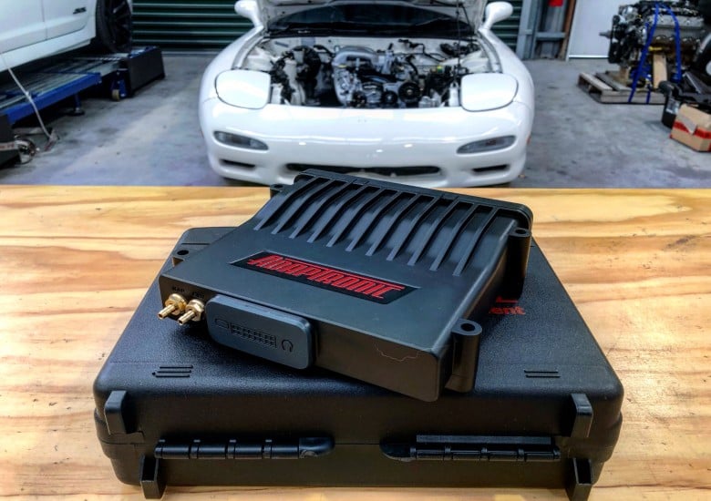
It’s not a particularly complex topic — some might even call it boring — but if you don’t understand what a pull-up resistor is and how to work with them within your chosen ECU, you’re asking for trouble. Read on to discover all the ins and outs of pull up resistors and you might just avoid a potential headache for yourself in the future.
In this article: What is a Pull-up Resistor? | Where Do We Need a Pull-up Resistor | Calculating Sensor Voltage | Configuring Your ECU | Conclusion
What is a Pull-up Resistor?
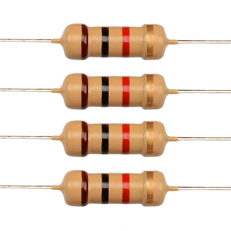
A pull-up resistor is used in a sensor or switch circuit in which the ECU can not determine the value that the sensor or switch is inputting. The resistor is used in conjunction with a 5-volt supply and restricts the flow of current to allow the circuit to have very low amps within it. This is vital because there’s no current draw in a digital switch, therefore if the resistor wasn’t used, the current would flow straight to sensor ground, damaging components in our ECU. The ECU only needs a voltage input to determine what state the switch or sensor is at, so if we use a 1k resistor on a 5 volt supply, we will reduce the current flow through the circuit to 0.005amp, which is not enough current to do damage if something goes wrong.
Where Do We Need a Pull-up Resistor?
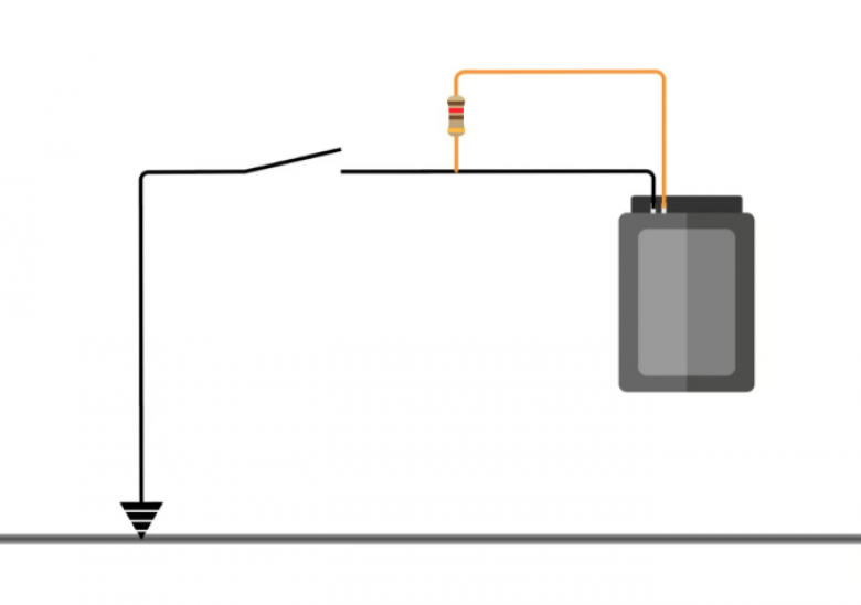
There are a couple of places that we’d need to use a pull-up resistor. The first is where a digital switch is used, such as in the circuit diagram above. The ECU is shown as the black box on the right and the switch is represented by the broken circuit, one side of which is connected to a zero volt — this will generally be a sensor ground zero volt circuit in our ECU. The other side is connected to the digital input pin on the ECU. In this diagram, the pull-up resistor is represented by the yellow line and has been wired externally, but most aftermarket ECUs will have the resistor built in, which we’ll be able to select different resistance values for, via the ECU software — in that case no wiring would be required.
While there isn’t a fixed resistance that must be used, a 1000-ohm resistor is favoured. Looking back at the diagram, the pull-up resistor is required to distinguish whether the switch is in the ground or open position. If this diagram didn’t use a pull-up resistor, when the switch is in the open position, the voltage that the ECU sees is going to be undetermined, as there’s no potential difference — this is known also as a floating pin. If the ECU header plug side of the pull-up resistor is connected to 5 volts, when the switch is open, 5 volts will also be present at our digital input pin. When we close the switch, this completes the circuit and we’ll end up with zero volts at the digital input pin. The pull-up resistor creates a small amount of current, which is why, when we switch to ground, we end up with the voltage dropping to zero volts. If we use a 1k resistor on a 5-volt supply, we reduce the current flow through the circuit to 0.005amp, which is not enough to do any damage.
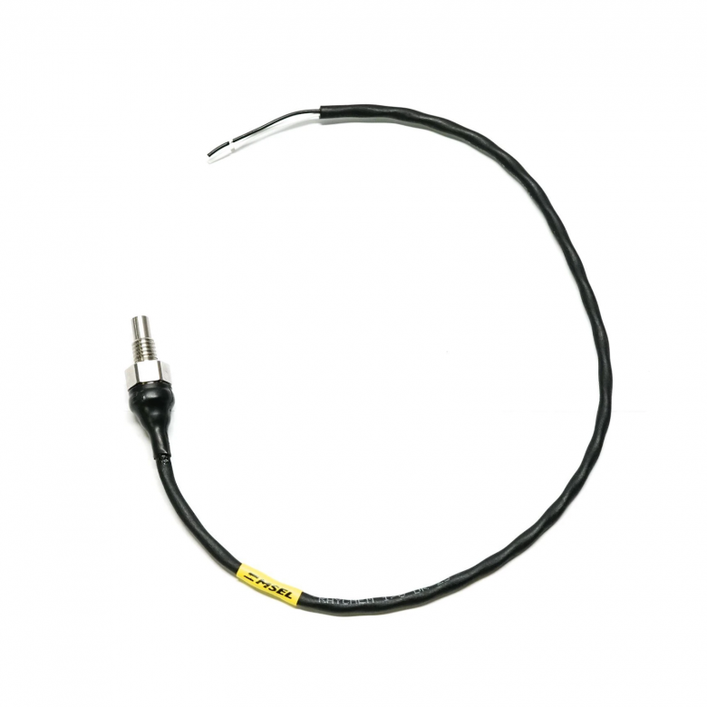
The other main use case for a pull-up resistor is when using an analog temperature sensor. The 1/8th NPT sensor pictured above is a negative temperature coefficient thermistor. This type of sensor only has two wires, and neither outputs any voltage, which is what your ECU requires to determine the temperature. Instead, the sensor changes resistance with temperature — the ECU is unable to detect a difference in resistance without sending a voltage to it. This is done through the 5-volt supply and a pull-up resistor. By having 5 volts in the circuit, we have changed from resistance to a variable voltage that the ECU can understand. Again, the pull-up resistor is used to keep the current in the circuit low to prevent a short to ground.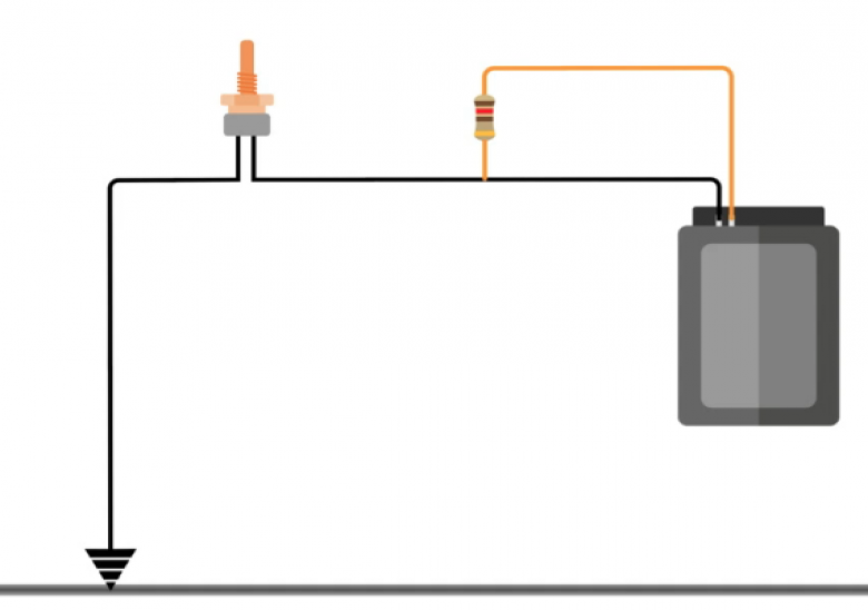
Here you can see the circuit for the temperature sensor. Essentially, it’s the same as the previous diagram, except the switch has been replaced with an air temperature sensor. In this case, we have a voltage divider sensor as we now have two resistors (the pull-up and the air temperature sensor) that control the amount of current flow between the 5-volt pin at the ECU and the ground on the opposite side. This means we’ll end up with a variable amount of voltage dependent on the resistance of the thermistor.
Above is a calibration table for the 1/8th NPT sensor from Motorsport Electronics. We have columns for temperature, resistance, and voltage. Having access to these voltages makes our job very easy but the data provided won’t always be this comprehensive. Because a lot of ECUs don’t have the ability to directly enter resistance, in many cases we’d need to calculate the voltage ourselves.
Calculating Sensor Voltage
Using Ohm’s law, once we know our voltage and resistance, we can work out the current flow in the circuit, and once we know that, we can determine what the voltage is going to be at the ECU. This can be worked out on paper using the formula V/IxR (voltage, divided by current, multiplied by resistance). As we already know our voltage is 5 volts, and our resistance is ???, we can now work out the current in the circuit. To work out the current at -20, we need to add the sensor resistance (72300ohms) to our pull-up resistor (1000ohms) resistance as they’re in series. We then input our readings into the formula to get 5/73300 (voltage divided by total resistance), which equals 0.00006821282amps. Now that we have the current, we can work out our voltage at -20. We do this by multiplying the current by the resistance at -20, which results in 4.932volts.
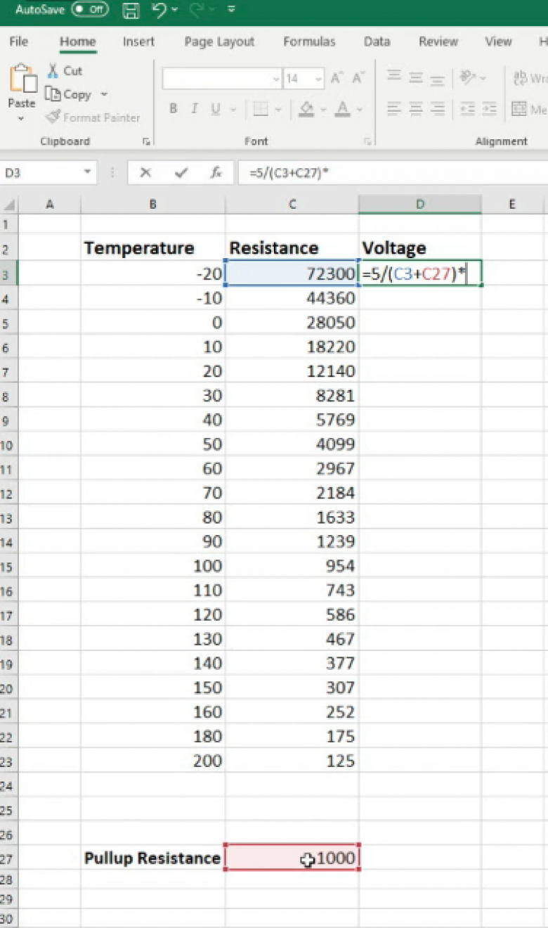
The second and perhaps easiest way to calculate this, is through Excel. To set this up, we’ll need columns for temperature, resistance, voltage, and also the resistance value of the pull-up resistor. Then, we can click on the first cell in the voltage value, type ‘=’ followed by 5 volts, divided by (/) our total resistance. To calculate our total resistance, we use an open bracket, then select the first resistance value, followed by the + symbol, select the pull-up resistor value and then closed bracket. This calculates the current through the circuit at a given temperature. We then need to multiply this by the resistance at that temperature to work out the voltage. This should look like =5/(C3+C37)*C3.
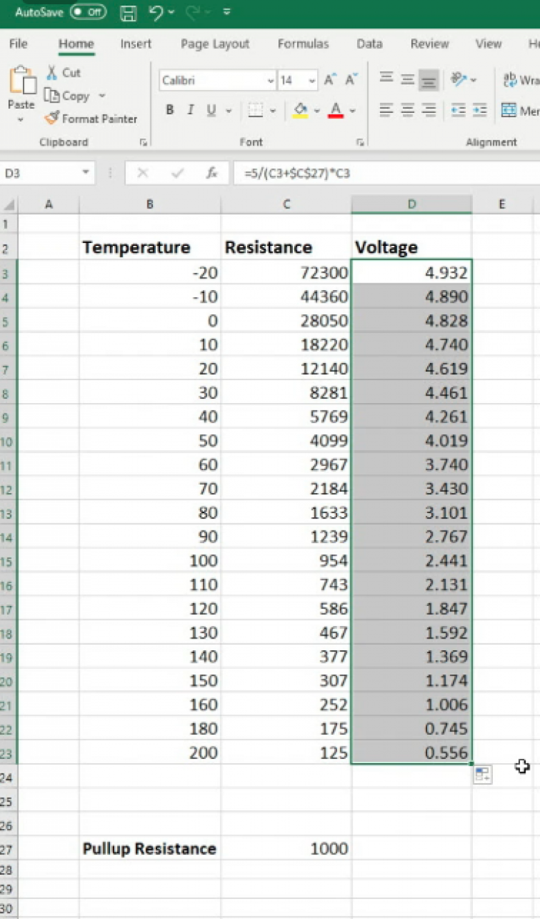
We can then drag that formula down to fill in the rest of the table. Before we do, make sure to put a $ sign on either side of the C in the pull-up resistance part of the formula that displays up the top of our spreadsheet. For example: $C$27. This will fix the value and stop it going haywire.
As you can see, we’re getting the same values as the calibration table provided. Easy, right? If we have a full calibration table with voltage included, obviously we won’t have to do this but even so, it’s still useful to be able to comprehend how these values were derived.
Configuring your ECU
Now that we know what a pull-up sensor does and where it should be used, let’s have a look at getting one of these analog temperature sensors into an ECU. Although we’ll be using a Link to demonstrate this, the principle is the same for all aftermarket ECUs. We have four analog temperature sensor inputs and 12 analog voltage inputs — what differentiates these for the majority of ECUs is that the analog temperature sensor inputs are for directly connecting to a negative temperature coefficient thermistor, whereas an analog voltage input is for connecting to a sensor that already outputs a variable voltage. The analog temperature sensor inputs have a built-in pull-up resistor inside the ECU. The analog voltage inputs, however, do not need for this as the sensor is already outputting a variable voltage.
[Need an image example here?]
By selecting our AN temp 1 input, we find a few parameters can be adjusted. Included in these is whether we’re using the internal pull-up resistor or wiring in an external one, and also the type of sensor we’re using. Most common sensors will have a predefined sensor selectable, however let’s have a look at how to set this up ourselves if necessary.
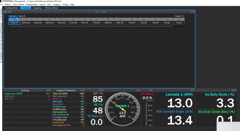
This can be done using the Cal table. We can change the input units to ohms or volts as well as set the temperature units, start point, and increments. Then, as we can see in the table above, we can simply enter the data from our sensor’s data sheet and we’ll have a working sensor.
For most tuners, this is as far as they’ll need to go. However, what should you do if you run out of analog temperature inputs on the ECU header plug and still need to add more temperature sensors to the ECU? Luckily, we’re able to repurpose an analog voltage input to enable the addition of a temperature sensor. To do this, we’ll need to wire in an external pull-up resistor to 5 volts at the ECU header plug, which we covered earlier. Just like last time, we have the CAL table that you will be using. In this case, because it is an analog voltage input, you will have to calibrate it in terms of voltage.
Conclusion
As you can see, there’s not a lot to pull-up resistors. However just because they’re straightforward, certainly doesn’t mean you can gloss over their functionality. They are an essential component that are worth understanding — knowing when and how to use them could save you from short-circuiting and potentially damaging your ECU.

