A perfect scan of an imperfect part just gives you a perfectly imperfect copy. Here's the workflow that fixes that.
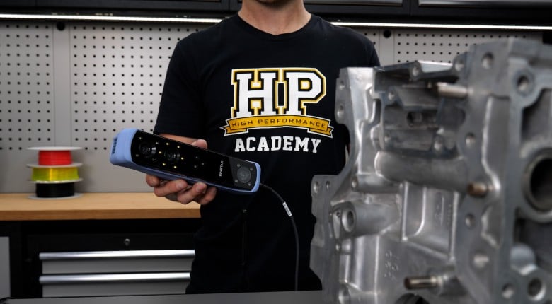
3D scanning doesn't just hand you a perfect CAD model - there's a crucial workflow in between that determines whether your scanned parts are actually usable. Derek Manson from FI Additives walks you through the real process of going from scanner to prototype to manufacture, including the software steps most people skip over.
Derek explains why you can't easily just scan and print, how to extract geometric entities from mesh files, and why accuracy depends on both resolution and scan area tolerance. Using a Dodge Ram example, he also demonstrates the complete workflow using a hydrogen injection manifold project. from scanning a gasket to prototyping with SLS printing to final metal 3D printing with quality assurance scanning on the back end.
If you're considering 3D scanning for reverse engineering, prototyping, or quality assurance, this video covers the technical realities you need to understand before diving in even if you're not using the same Creaform VX software discussed here.
--------------------
TIMESTAMPS
0:00 - Derek Manson
0:18 - Why a Scan Is Not Finished CAD
0:39 - Creaform VX Software Overview
1:12 - Extracting Entities From Scan Mesh
1:36 - Planes, Cylinders, Cones, Sections
2:19 - Accurate Measurement Without Human Error
2:47 - Mesh Repair and Noise Cleanup
3:46 - Auto Surfacing Limits
4:52 - QA Scan Overlay vs CAD
5:37 - Accuracy vs Scan Area Tolerance
6:49 - Hydrogen Injection Manifold Example
7:27 - SLS Prototype and Design Review Changes
8:07 - Why Additive Works | Internal Geometry
8:44 - Scan Printed Parts for QA
9:04 - Printing vs Machining Tolerances
9:45 - FI Additives