Modern EFI system are always offering us advanced new features to improve the performance of our cars and it’s getting easier than ever to go faster with safety. One technology that is critical if you have a powerful car and don’t want to end up all crossed up like our Toyota 86 pictured, is traction control.
Traction control works by monitoring the wheel speeds of the driven and undriven wheels. When the car begins to wheel spin, the driven wheel speed will be higher than the undriven wheel speed and the ECU can look at the difference and calculate the percentage of slip. Contrary to what most people would think, if we want maximum acceleration a small amount of slip is actually desirable and maximum acceleration is achieved with somewhere around 10% wheel slip.
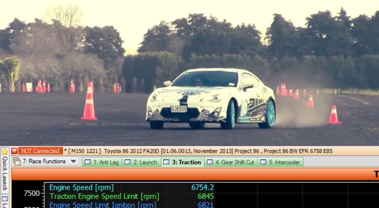
A common way of implementing traction control is by the ECU targeting a certain slip percent and then using a PID control algorithm to adjust ignition retard, ignition cut, throttle position or sometimes all three to achieve the target. This can be extremely effective when tuned right, however getting the control strategy perfect is time consuming. One function that every ECU manufacturer has spent a lot of time optimising however is an effective rev limit so let’s look at how the Motec M1 implements a rev limit to control wheel slip.
If the ECU knows what the undriven wheel speed is as well as the gear ratio, final drive ratio and rolling diameter of the wheels, it can calculate what the theoretical engine rpm should be to achieve a certain road speed. This would be the engine rpm with no wheel spin. Once the ECU knows what the rpm should be, it can introduce an engine rev limit slightly above this level that will target the desired level of slip - For example let’s say the ‘zero slip’ rpm is 4000. If we set the traction rev limit to 4400 rpm at this point, it will allow a 10% slip.

The data log shows acceleration through second gear in our turbocharged Toyota 86 test vehicle on a wet road. Normally this would result in uncontrolled wheel spin and very little acceleration. In the data log, the light blue line is the actual engine rpm, while the dark blue line is the traction control rev limit. You can see as the driver hits full throttle, the engine rpm constantly bounces up to the traction control limit but never exceeds it. The green line shows the throttle position is wide open through the entire test.
The last group in the log shows the ignition cut being applied by the MoTeC M1 ECU. Each time the ignition is cut to reduce engine power, the ignition output cut count increments.
We are about to start shooting our new ‘Advanced Functions’ course which will detail how functions such as traction control, launch control, antilag and gear shift control work. The initial release will also include worked examples on the Motec M1 platform to give you a step by step approach that explains how each function works, how to configure it and finally how to correctly tune it.
If this sounds like you, join up to HPA as a Bronze member (it’s free) and we will let you know when the new course is ready.