Sale ends todayGet 30% off any course (excluding packages)
Ends in --- --- ---
Notice most manufacturers recommend installing a 100R resistor on one end of the CAN Bus line. How does one usually crimp one on and how? Thanks.
G'day John.
A good way to do this reliably is to use a DTM 2-pin female connector that has a backshell on it for booting, like this
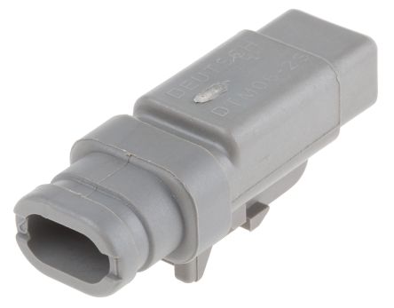
You then crimp the legs of the resistor to the terminals quite close, and insert them so the resistor is inside the backshell. Then you fill the backshell with potting compound which stops the resistor from being able to move and its legs fracture.
On your main harness you then wire the corresponding DTM 2-pin male connector to the end of the CANBus. Plug in the terminator you've made and its good to go :-).
Thanks Zac, for longer runs I am told that we should put one in the front and one at the end of the run. What is considered a long run where this consideration should be factored into the run. Also, how do you wire up your CAN Bus trunk so that you can put multiple Deutsch connector to connect various CAN devices. Do you just splice a pigtail off the main trunk and extend to CAN device? Thanks.
https://knowledge.ni.com/KnowledgeArticleDetails?id=kA00Z000000P7ikSAC
CAN specification is for two 120 ohm terminating resistors on each end of the main bus line, regardless of run length. They can be close, no need to be exact. The link I provided describes how to lay out the bus and stubs.
G'day John.
Yes, the spec calls for termination resistors at either end of the bus, no matter the length. My experience however is that it does not make a huge difference for the length of busses we're running in an automotive application. I've seen the difference in a ~30m bus I setup to communicate between some machinery though. Once you get up to longer lengths the reflections of the signal from the end of the wire, or last component on the bus become a real thing that needs to be dealt with.
Often, it's not actually achievable to have a resistor at either end, as multiple connected devices might have built in termination resistors. Its a problem in the automotive aftermarket / motorsport worlds that is becoming more frustrating as we put more CAN devices into vehicles. It's only a few cents of components to add to a device to allow it to have a switchable termination resistor, or at the very least they should not put them in at all, so we can define where they are ourselves... But that's just one mans opinion ;-). But I digress....
To answer your question, I'd call a 'long run' anything 5m or greater. Try to get termination resistors at either end regardless, but it will most likely come down to a case of 'try and see'. If you've got access to an oscilloscope you can have a look at the shape of the signals on the bus, particularly what the edges look like, you want them nice and sharp.
For splicing into the bus, yes I typically tap into it near the branch point that heads off to the device that needs the connection.
Thanks. SO i just found out I am using a LTC (Lambda to CAN) module from MOTEC and need to run a CAN bus into the engine harness side. I do have a few spare cables but they are not twisted like it is suggested. This is a short distance of about 1 Meter from Firewall to EMS. Will it be an issue?
1 meter untwisted should be fine. Just try to keep the pair close together. What you don't want is your high and low wires being spread apart.
Roger that!! Thank you..Does it matter if it is close to the 12V sensor power like crank and cam sensors?
No, the bus works off of a differential pair. It is very resilient to noise as long as both lines are subjected to the same noise hence why they shouldbe closer together.
is using the DTM04-2S-P006 connector another option of doing this as well. Seems to have a 110 ohm resistor in it internally.
https://www.mouser.com/datasheet/2/418/NG_CD_DTM06-2S-P006_B-960852.pdf
I run the internally resisted 3 position DT and 2 position DTM connectors exclusively (as you've linked to, and also my supplier happens to be Mouser). I've also used Zac's method but it was always something that nagged at me when vehicles would go on rough tracks etc.
If you're doing a 'simple' or permanent CAN install I'd go with the DTMs as they're obviously more suited due to their size however if you've got some weird design requirements/very long runs the DT's are nice to run as they've also got a line of 3 way splitters for the 3 position connectors (HI, LO, Shield) if you need to break off the trunk etc.
Is there a general recommended limit to how long the branched device is away from the CAN bus trunk?
I believe the spec states 500mm (~19")