Sale ends todayGet 30% off any course (excluding packages)
Ends in --- --- ---
Hello. I'm hoping to build a patch harness to connect an Emtron KV8 to my stock harness and am hoping to get advice here.
First questions relate to the connection from the KV8 to a laptop. The KV8 connects to a laptop with a CAT5 plug (ethernet). Emtron sells a cable that goes from the connector on the KV8 (pinned wires) to some sort of metal quick disconnect connector that looks something like a microphone plug and they also sell a corresponding cable that is the other side of that connector to a CAT5 plug. Does anyone know what kind of quick disconnect connector they are using and why they chose that one? It's not obvious to me why they don't use a CAT5 connector in the middle, which would probably be much less expensive. Is the style they use waterproof when disconnected, perhaps? I'll attach photos of the cables.
Thanks!
Hello Richard,
It looks like a Unipole B series, which is apparently not waterproof like the K series. Here is the catalogue for the Unipole. Attached is the pinout, if you wanted to bypass it. I am not familiar with the Emtron products, so am not sure if this would be problematic. Looking at the pinout, I would be surprised if this caused an issue.
Thanks, Callum. That helps. Next question: What is the best way to attach wires to the ECU header? It has two rows of pins bent at a 90 degree angle for soldering to a circuit board. I'm starting with a new header, so no de-soldering required, but what is the best way to attach wires to those pins?
I've seen YouTube videos where people bend those pins straight with pliers, clip them shorter and then solder the wire and cover them with heat shrink. I'm not sure if using SolderSleeve wire splices might be a less labor intensive approach to this?
Also, any advice for strain relief on those wires? I've seen one YouTube video where someone used painters tape to create a reservoir of sorts and then added JB Weld epoxy to form a rectangular brick of hardened epoxy around all of the wires. That seemed like an approach that would work. Not sure if there is a more professional way of doing that?
Thanks in advance for any suggestions. I plan to keep posting in this thread as new things come up.
Rich
There are header plugs available that take crimp contacts & have a reservoir, but since you already have the others, straighten the pins & solder the conductors to them. Don't put heat shrink on them, just make sure they aren't touching as you go. Once done, make a reservoir, but line the inner walls with kapton tape. Then fill the reservoir with either ResinTech RT125, Hellermann Tyton V9500 or TE S1125 potting compounds, with a syringe & needle, ensuring you get in and around all the gaps. Make a decent depth reservoir so that they are well strain relieved and give the potting compound at least 24 hrs to set. This is a tried & proven reliable technique.
Yes they're Lemo Unipoles and no there's no trickery with regards to wiring them up directly to an RJ45 using the available schematic. I've never understood their aversion to using a sealed and hardened RJ45 receptacle and haven't gotten a satisfactory answer even though I'm an Emtron dealer :|
With regards to creating the patch harness, if theres one available I always suggest using a breakout board with the harness' receptacle on one side and a short lead termination of your ABCD connectors on the other. Pot it entirely once you're satisfied.
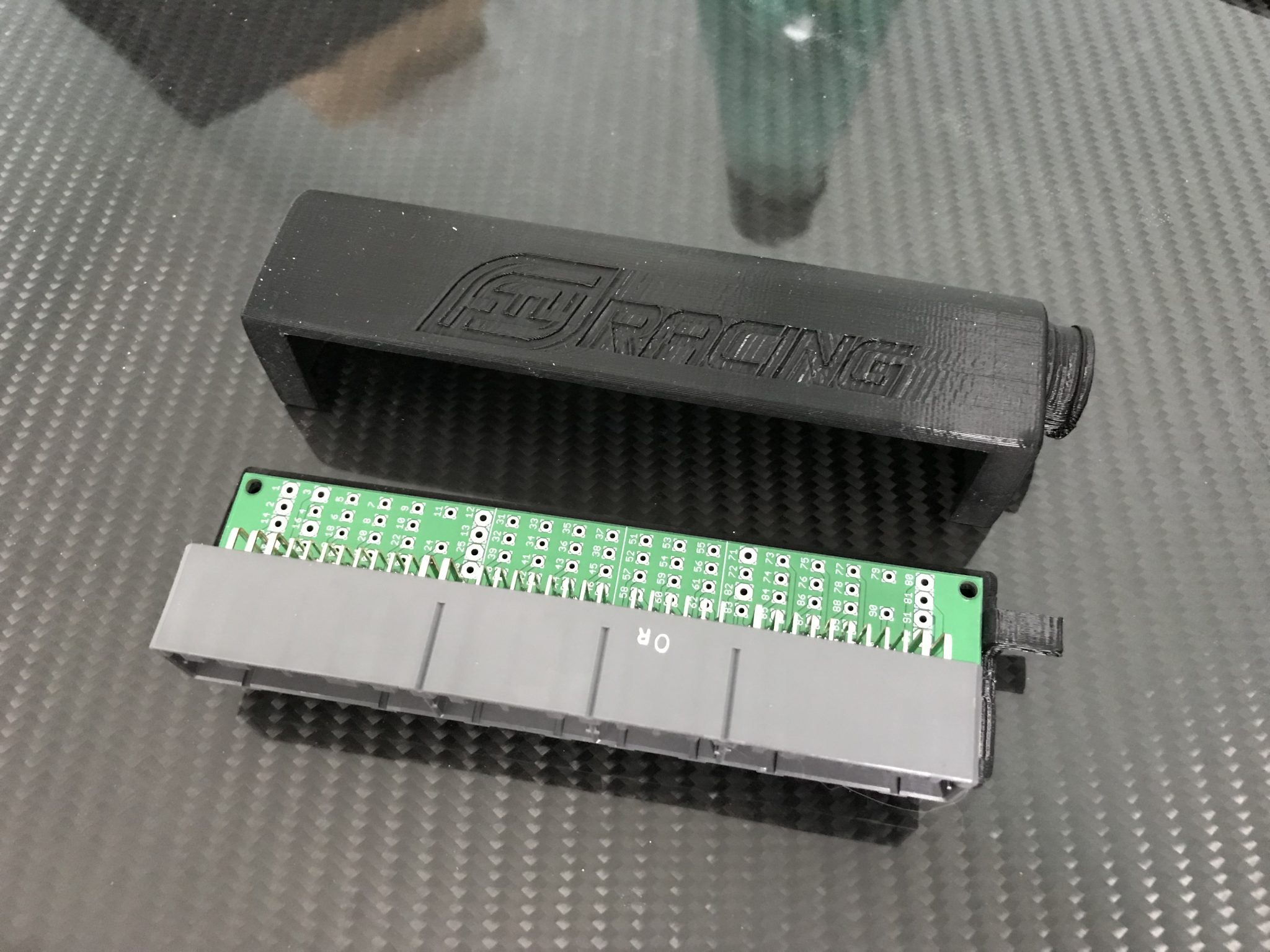
Here's one example available for DSMs of your vintage:
https://ftyracing.com/product/2g-dsm-evo8-ecu-breakout-board/
Thanks all. I just ordered that FTY breakout board to hopefully make this all a bit cleaner and more durable.
David, could you provide a little more description to a novice of what you mean by using the breakout board "with the harness receptacle on one side and a short lead termination" of the connectors on the other. I'm pretty clear on how to pin the connectors from the HPA videos, but I'm not so sure how to go about the other end. I assume each wire is soldered into one of those holes on the board. How should I go about bundling or sheathing the wires and providing strain relief? I searched online for a photo of one of these breakout boards finished in an automotive ECU application and came up short.
Thanks again!
Rich
Yes you'd essentially solder a lead to each 'via' (holes on the board) which has a trace to the correct pin on the receptacle header which is positively affixed to the board.
Since the photo I posted from FTY Racing has a 90* backshell I'd solder them long/wild, orient and bend the leads in the desired 90, then trim to length, and crimp contacts to populate the KV8s ABCD Superseals from there. That printed shell - that I believe comes with the board comes with - has a strain relief to the right to affix your leads to and you can also silastic coat or epoxy the PCB afterwards if you're concerned with solder joins fracturing.
Sometimes I forget to pop in but feel free to keep asking questions here or just email me, david@machine-ep.com
I'm trying to figure out what AWG sizes to use. But as a preliminary question, should I worry about the AWG of the stock wiring to the power input to the ECU? I'm not sure how to even check that. Everyone installs these aftermarket ECUs with jumper harnesses using the stock ECU wiring and not worrying about this, so am I worried over nothing?
As a general rule people tend to think they need to go overboard with current capacity of their patch/wiring harnesses. That said, if you've got current draw that's going to something weird that can draw a lot of current, step it up.
I tend to just do a blanket of 20 AWG if I don't want to take the time, though 22 AWG will suffice more often than not.


