Sale ends todayGet 30% off any course (excluding packages)
Ends in --- --- ---
I'm wiring my stock Toyota 2-wire fuel sender to my AIM MXS Strada dash. I know I need to create a voltage divider circuit by placing a 1kOhm 1/4watt resistor between the dash's 5v output and chosen aux input, but I'm not sure of the neatest way to contain the resistor!
How do other folk wire up this kind of circuit? Any tricks to hide the resistor in the back of a plug etc?
Cheers,
Mark
G'day Mark.
Have to be careful adding in resistors, as the leads are a solid core, so are prone to fracture.
I like to hide them behind connectors, the key is to make sure the entire resistor and its crimp connection is strain relieved and supported in some SCL shrink. For this reason, I don't like to include them in the crimp connection to the connector pin, but instead will remove a section of insulation from the wire that is crimped to the pin, and splice the resistor in here. The resistor body, its splice connections and the two wires to which it is connected them all get sheathed in a piece of SCL to make sure they're rigid, and move as a unit, ensuring the resistor legs won't fracture.
I'm finding it hard to explain clearly... I'll do a wee sample a post a pic, gimme a few.... :-).
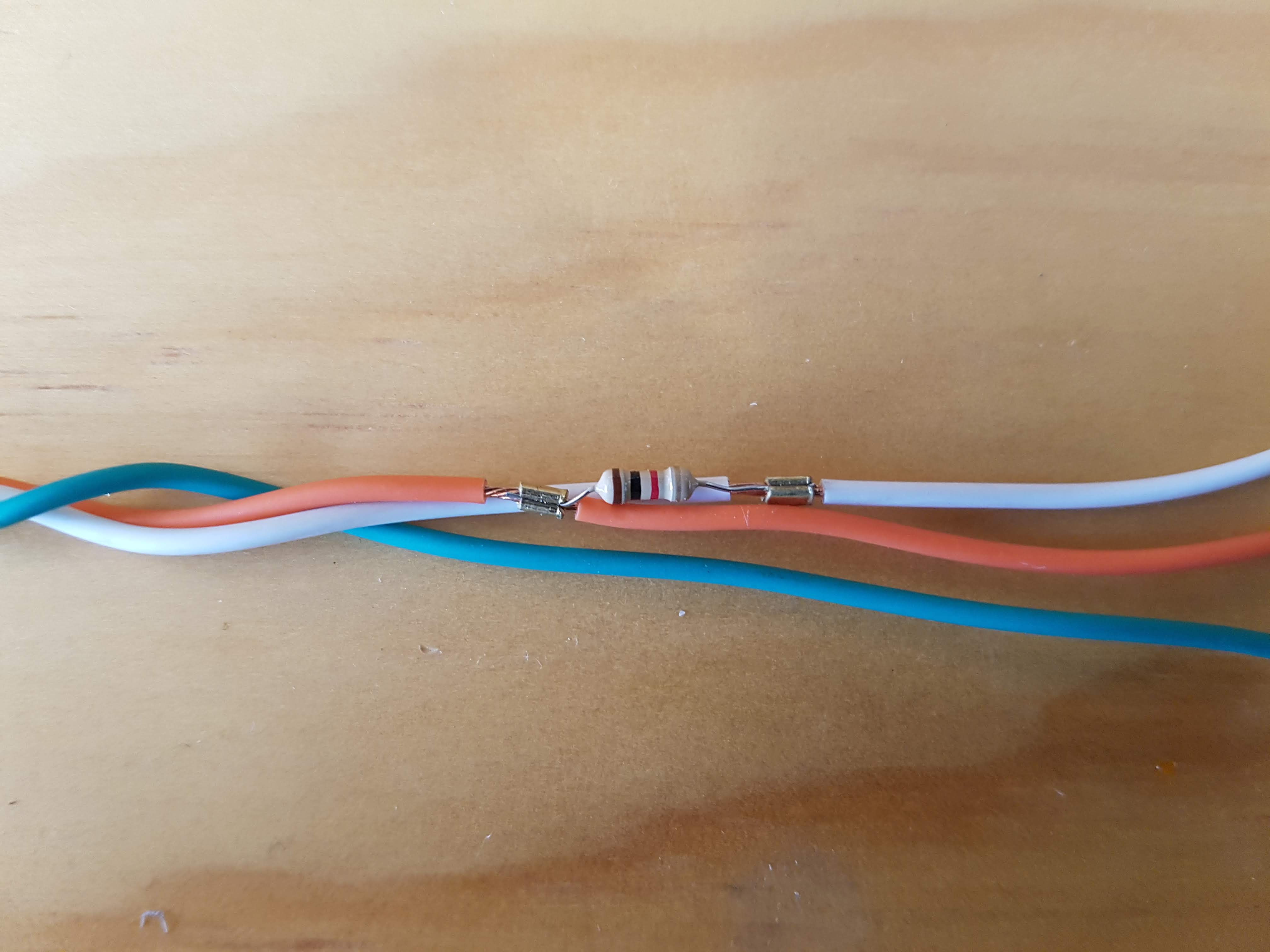
I havent shown it, but remember, its crucial that the entire resistor body, legs and crimped sections are strain relieved as one with some rigid SCL, will ensure those resistor legs don't vibrate and fracture :-).
That’s exactly the pointer I was looking for. Thank you sir!
If you can bend one of the resistor legs around you can get them to take up less space, but it gets tricky to make the actual crimp, and need to be careful about the splice staggering and insulation :-).
Would you employ the same technique to wire a FIA cutoff switch ballast resistor? I guess heat is more of an issue in that situation, but the huge resistor seems rather flimsy unless covered in SCL or similar...
I think in that situation I'd crimp the larger solid core legs of the ballast resistor to some DTM pins, and have the resistor immediately behind the connector, then pot / scl / strain relieve the whole lot to make it a rigid assembly. This gives you a ballast resistor with a DTM connector on it, the other side of that DTM connector you then install on the kill switch to allow the alternator somewhere to run down into if the motor gets killed.
Thanks Zac, I’ll give that a go.


