Sale ends todayGet 30% off any course (excluding packages)
Ends in --- --- ---
Background and tests so far:
Turbosmart Power Gate 60, with two 7lb springs. MAC 4 port solenoid controlled by M150.
I set M150 feedforward to 0 and “boost cut” to 21psi, but still hit boost cut.
I did have an issue early on where I was new to the Turbosmart wastegate and wasn’t used to having a valve seat… probably didn’t help taking 4yrs on this build. Not sure it is related but I did melt two valve position sensors due to the seat being out and essentially passing exhaust gas 100% of the time.
Tests and changes made so far: I’ve ran compressed air at various settings through the wastegate hoses… both on and off the car. With both 7lb springs it took almost 21psi to fully open the wastegate.
I took the inner 7lb spring out and it was taking approximately 12psi compressed air to fully open the wastegate. But I am still hitting boost cut.
When using compressed air a fully open wastegate will tack ~14mm of opening on my M150, but the most I see it opening from my logs off the turbo pressure source is around 8mm. I understand manifold design can affect boost creep, but would expect the pressure line to still open the wastegate fully. I’m using -3AN Brown Miller Racing lines and have tested the lines to be good.
I think the manifold design is solid, but have uploaded a picture for reference
Do you still have numbers in the boost aim table? Do you have non zero values in the PID gains? also what are your boost control enable, activate, and margin values?
Boost enable is the throttle percentage that boost control becomes active. Activate is the point the system goes into closed loop. Margin is the deviation from the aim before maximum control is applied.
Have you checked to confirm the fittings in your 4 port solenoid and all your lines have no leaks? Where is the pressure source for the boost control system from?
Is there any reason you used -3AN hose for a 60mm gate? I have always stepped up to -4AN hose on 50 and 60mm gates, as in my experience the extra flow of the larger line comes into play.
I would also recommend plumbing the wastegate directly to your pressure source (which I hope is the compressor cover or at least pre throttle body) and testing the behaviour.
Thanks for the list of things to check, especially the Motec settings.
I’ve checked all the lines and MAC solenoid. I’ve ran compressed air and various pressure levels.
I’ve not yet ran the pressure line directly to the wastegate, but was likely going to be my next step.
The pressure source is right after the compressor housing on my intercooler pipe.
Not sure about the lines. I was wondering if the WG might need more volume of air, but the lines seem to be working fine and imagine they’re more responsive to pressure change.
Thanks again for the suggestions. I will check the M150 settings when I get in front of my computer again.
What engine and power levels are you looking at, I was wondering if the valve capacity may be insufficient, especially as the 90 degree take-off is less efficient?
However, even without that being a possible concern, you would seem to be having a problem with the valve even opening fully - have you been able to double check those opening points are actually accurate?
I assume you've checked for kinks and other possible restrictions, while double checking the hose positions, but is it possible the atmospheric out is restricted?
If it turns out the valve is fully opening, it might be down to the valve size and pipework size and orientation, especially if it's plumbed back into the down-pipe, limiting it's ability to dump the gasses?
I assume you've worked your way through the installation and test setups for the valve, found on their site here - https://www.turbosmart.com/wp-content/uploads/instructions/External_Wastegate_EWG_38mm_40mm_45mm_50mm_50mm_GenV_Standard_Motorsport_Fitment_Instructions/English.html
It’s a built 2JZ with a Garrett GTX3584RS, should produce around 925whp, but still working out some bugs.
I think the manifold picture might be a bit deceiving. Here is a video of the billet collector.
I will check the hoses again. Thanks for the suggestions.
That is CNC porn! Assuming the valve is actually opening fully, it may still be possible for the runners opposite the pressure bleed to bypass it due to gas velocity. However, I'll bow to those with more experience of flange design on that.
Sounds like a fun car.
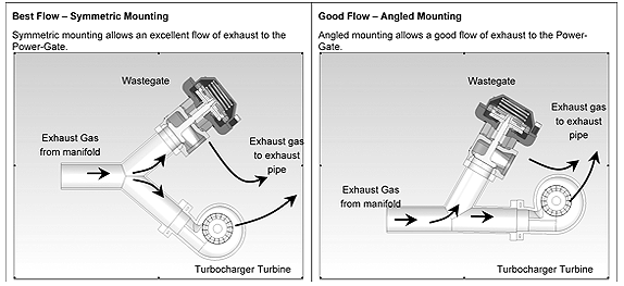
I think your issue could be the manifold design. As this Turbosmart picture illustrates, you want the path to the wastgate and the compressor to be similar, and yours is very much more efficient going to the compressor.
While I haven’t / won’t rule out the manifold flow. I would still expect 21psi at the compressor outlet to act against the wastegate diaphragm and open it completely… especially with a 7lb spring and since 12psi from my air compressor opened it fully.
Still need to bypass the solenoid and run the hose directly from the compressor to the bottom of the gate.
I did compare a larger hose and while it seemed to flow more air when “observing” it with compressed air. I also tried it back to back on the gate and the ability to affect the amount the valve opened. I didn’t measure a noticeable difference of valve opening in the the M150.
I also noticed that while the bottom gate has the 1/4NPT opening it has a smaller “opening/pass through” into the diaphragm chamber. So not completely convinced that moving to a -4 line will make a noticeable difference.
more to come.
Update… I disassembled the wastegate again just to double check everything, and bypassed the 4 port MAC valve. On the 7psi spring this method was able to fully open the wastegate and consistently hold 10psi of boost.
I also checked with Turbosmart and they said the difference between -3 and -4 wouldn’t be noticeable.
I did notice that I had a few different versions of 1/8NPT to -3AN adapters and some of them had a slightly bigger opening on the NPT side. I made sure I used the one with the biggest opening on the bottom wastegate port. As I mentioned in a previous update the bottom port has a smaller diameter port that in’s into the chamber and it sits on the bottom portion of the NPT opening. Some the NPT fitting doesn’t bottom out I doubt this makes a difference, but I wanted to minimize any potential airflow restrictions / changes.
Next step I will reconnect the boost solenoid and run through some of the settings. Though zeroing out the feedforward table would effectively leave the gate “off” and 100% of the pressure reference source would feed into the wastegate.
Well, the good news is that the 'gate is apparently able to bleed off the pressure, so it would seem the next thing is to look at the control of the gate.
Glad to see you were able to rule out most of the mechanical question marks.
As the MoTeC boost control system is designed entirely to be used as a closed loop system, its hard to make it operate with any kind of open loop strategy.
I would recommend as a next step refitting your boost control lines and solenoid, and leaving the solenoid unplugged, provided you have it plumbed like the attached image. this will leave the top of the gate open to atmosphere and your pressure source feeding the bottom of the wastegate.
It wouldn't hurt to just blow through the hoses. your should be able to blow through the either of the bottom two hoses and have air pass through the other bottom hose, and not either of the top hoses with the solenoid not energised. likewise with the top it should exhibit the same behaviour (through the top hoses and not through the bottom) If the results deviate from this, there may be an internal issue with the solenoid
If the same behaviour is produced as the direct line method (relatively, as you have added some extra items for the air to navigate) but behaviour should end up being the same. If all is correct, and behaves correctly, you will need to start checking through your boost control setup in the MoTeC. It also wouldnt hurt to check your wiring (you may have the wires shorted together holding the valve open)


