Sale ends todayGet 30% off any course (excluding packages)
Ends in --- --- ---
Discussion and questions related to the course PDM Installation & Configuration
I've seen on "ECUMASTER PMU16 WORKED EXAMPLE" that the wire gauge for the alternator field is 16AWG and the current draw could be 5A steady and could go higher through 15A.
I would like to understand this better because I though this was just a signal to excite the alternator on. I wasn't aware that it could draw this much current. And also, if it draws only 5A, a 22AWG tefzel wire wouldn't be enough?
I think it would be nice to have an webinar dedicated to alternator control, this is a subject on the aftermarket ECUs that have a very low coverage (it's very hard to find threads discussing about it), going all the way through the simple 1 wire alternators to the most modern types. How to wire them, which ECUs have the capabilities to control them, how to setup this ECUs to control this alternators and so on.
- - - - - EDIT - - - - -
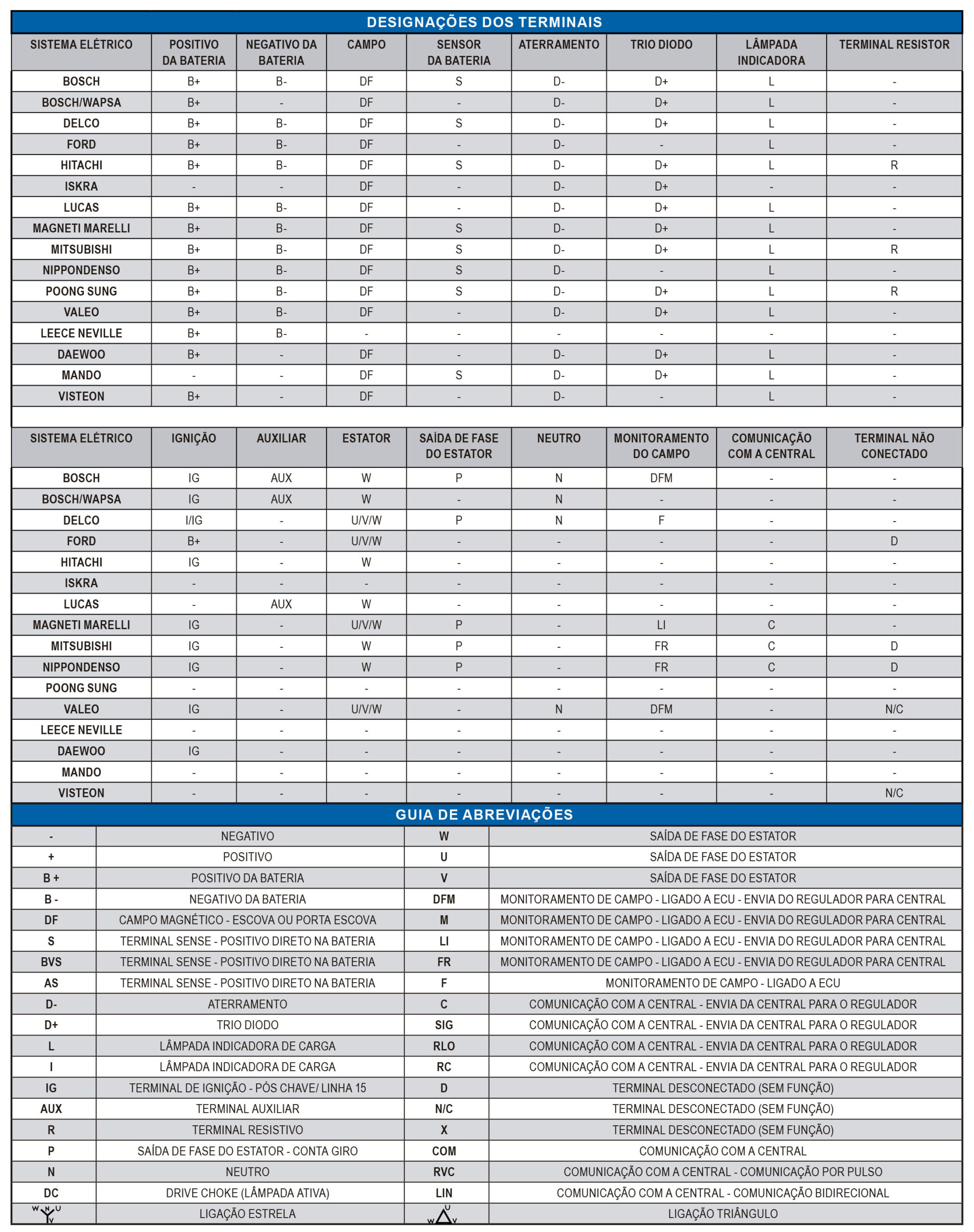
There is an aftermarket voltage regulator manufacturer that makes available some technical bulletins on several regulator models (it is in Brazilian Portuguese, but with some translation tools it could be helpful for anyone around the planet):
I like this idea also, have read numerous threads about alternators and how to wire them but something specific which was in depth and covered the many ways to wire in would be extremely helpful.
I would agree, as some which use a in-series warning light use a 3 or 5W bulb, which would limit it to well under a half amp'.
HOWEVER, there have been many, many different alternator wiring configurations and alternator designs in the last couple of decades, which rather confuses things.
For those using aftermarket alternators it's bit easier, though, as many (re)manufacturers have wiring schematics and wiring recommendations on their web sites.
Do you chaps have specific applications in mind?
Oh, forgot, don't recall the specifics, but might it have also been used as the power/ground for other circuits?
Let's use the following regulators as an example:
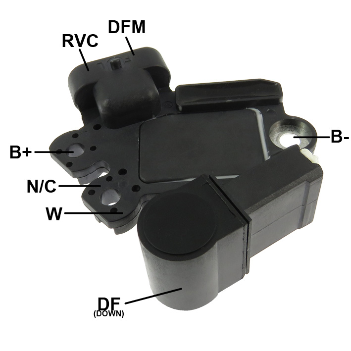
Ford 3 pin (used on Brazilian Ford Fiesta, Ford Ka,...):

DFM, L, S
DFM = ECU signal
L = light
S = battery sense
DFM is the output signal from the ECU to the alternator. From what I have understood, each manufacturer uses a different signal. How I can discover which signal it is?
L is the bulb to excite the alternator, if I use the bulb, it draws less current so a 22 awg tefzel wire would be enough? If I wire it directly to a PDM output I should use a larger gauge since it will draw a significant current.
S is the battery sense, I thought it was meant to be wired to the ECU, so it can adjust how the alternator should operate. But looking at the diagram, it is wired to the battery. Why the voltage regulator is not wired internally directly to the B+ terminal? A 22 awg wire would be just fine since it draws a very small current, right?
Another case:
I'm aware that late GM models sold in Brazilian market have a pin called DFM. Some others have DFM and RVC.
Some one knows exactly how this kind of alternator works?
On this spec sheet from GAUSS, it says DFM = Field Monitoring, it goes FROM the regulator TO the ECU. RVC = Communication with ECU (Modulated Signal)
I have found this threads with some info about it:
https://www.electro-tech-online.com/threads/lin-or-dfm-fr-alternator-question.162362/
https://vehiclechef.com/what-is-w-terminal-on-an-alternator/


